Dynamo and BIM: Visual Programming Software in BIM Evolution
VerifiedAdded on 2022/08/20
|50
|19073
|28
Thesis and Dissertation
AI Summary
This dissertation investigates the significant contribution of Dynamo visual programming software to the evolution of Building Information Modeling (BIM). The study provides a comprehensive overview, beginning with an introduction that outlines the background, purpose, aims, and limitations of the research. It explores the current state of BIM, the value of BIM in building design, and the functionalities of Autodesk Revit. A detailed literature review covers the history and definition of BIM, the capabilities of Revit, and the concept of Dynamo visual programming software, including its value in Revit and its connection to object-oriented programming and Application Project Interface (API). The methodology chapter outlines the experimental approach, including the use of Dynamo scripts for elements placement and a case study. The results chapter presents and discusses the experimental outcomes related to parameterization in BIM models. Finally, the conclusion and recommendations summarize the study's findings and suggest areas for further research, emphasizing the role of Dynamo in enhancing design ideation and driving BIM evolution through parametric design and computational tools.
DYNAMO and BIM
THE CONTRIBUTION OF DYNAMO VISUAL PROGRAMMING SOFTWARE IN THE
EVOLUTION OF BIM
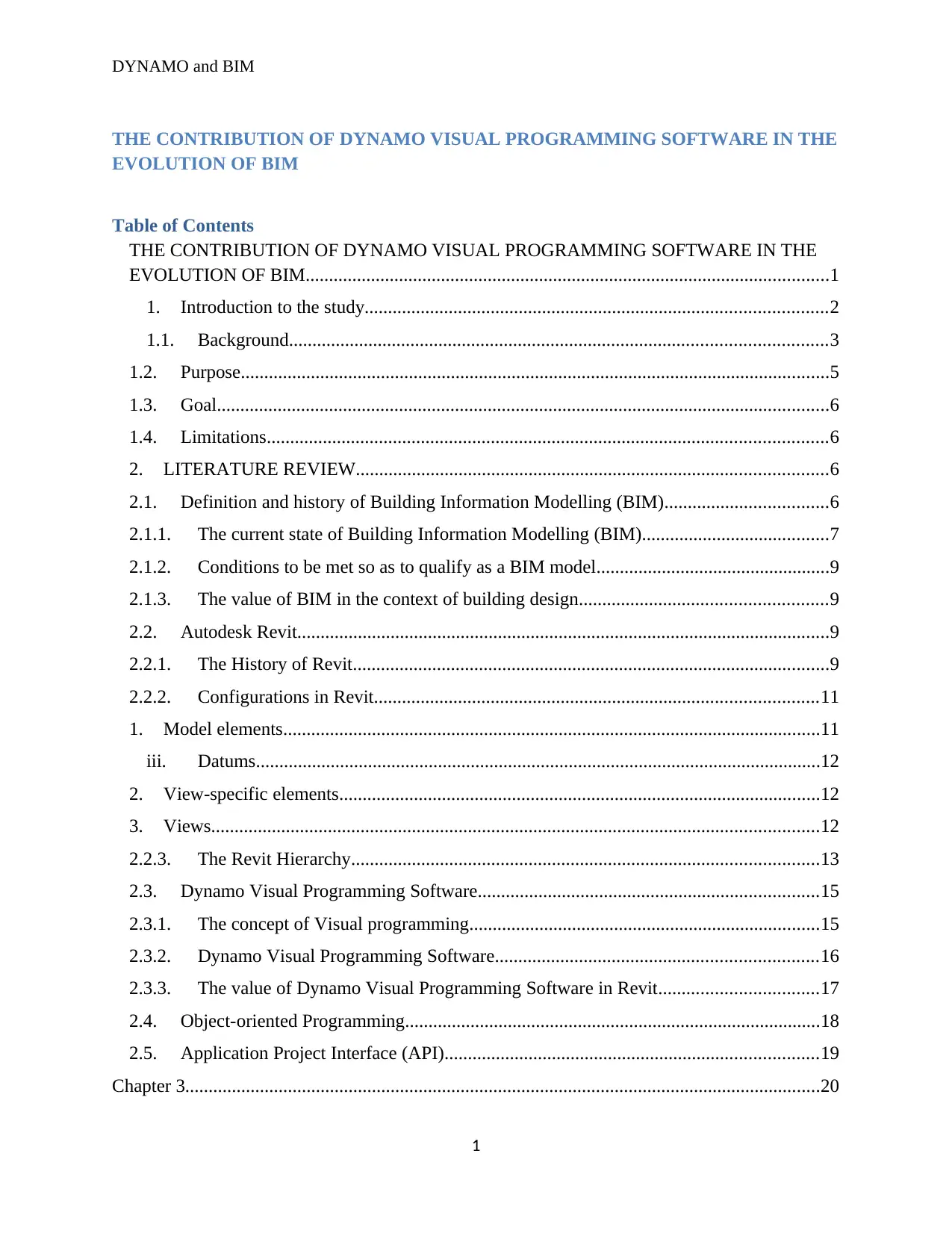
Table of Contents
THE CONTRIBUTION OF DYNAMO VISUAL PROGRAMMING SOFTWARE IN THE
EVOLUTION OF BIM................................................................................................................1
1. Introduction to the study...................................................................................................2
1.1. Background...................................................................................................................3
1.2. Purpose..............................................................................................................................5
1.3. Goal...................................................................................................................................6
1.4. Limitations........................................................................................................................6
2. LITERATURE REVIEW.....................................................................................................6
2.1. Definition and history of Building Information Modelling (BIM)...................................6
2.1.1. The current state of Building Information Modelling (BIM)........................................7
2.1.2. Conditions to be met so as to qualify as a BIM model..................................................9
2.1.3. The value of BIM in the context of building design.....................................................9
2.2. Autodesk Revit..................................................................................................................9
2.2.1. The History of Revit......................................................................................................9
2.2.2. Configurations in Revit...............................................................................................11
1. Model elements...................................................................................................................11
iii. Datums.........................................................................................................................12
2. View-specific elements.......................................................................................................12
3. Views..................................................................................................................................12
2.2.3. The Revit Hierarchy....................................................................................................13
2.3. Dynamo Visual Programming Software.........................................................................15
2.3.1. The concept of Visual programming...........................................................................15
2.3.2. Dynamo Visual Programming Software.....................................................................16
2.3.3. The value of Dynamo Visual Programming Software in Revit..................................17
2.4. Object-oriented Programming.........................................................................................18
2.5. Application Project Interface (API)................................................................................19
Chapter 3........................................................................................................................................20
1
THE CONTRIBUTION OF DYNAMO VISUAL PROGRAMMING SOFTWARE IN THE
EVOLUTION OF BIM
Table of Contents
THE CONTRIBUTION OF DYNAMO VISUAL PROGRAMMING SOFTWARE IN THE
EVOLUTION OF BIM................................................................................................................1
1. Introduction to the study...................................................................................................2
1.1. Background...................................................................................................................3
1.2. Purpose..............................................................................................................................5
1.3. Goal...................................................................................................................................6
1.4. Limitations........................................................................................................................6
2. LITERATURE REVIEW.....................................................................................................6
2.1. Definition and history of Building Information Modelling (BIM)...................................6
2.1.1. The current state of Building Information Modelling (BIM)........................................7
2.1.2. Conditions to be met so as to qualify as a BIM model..................................................9
2.1.3. The value of BIM in the context of building design.....................................................9
2.2. Autodesk Revit..................................................................................................................9
2.2.1. The History of Revit......................................................................................................9
2.2.2. Configurations in Revit...............................................................................................11
1. Model elements...................................................................................................................11
iii. Datums.........................................................................................................................12
2. View-specific elements.......................................................................................................12
3. Views..................................................................................................................................12
2.2.3. The Revit Hierarchy....................................................................................................13
2.3. Dynamo Visual Programming Software.........................................................................15
2.3.1. The concept of Visual programming...........................................................................15
2.3.2. Dynamo Visual Programming Software.....................................................................16
2.3.3. The value of Dynamo Visual Programming Software in Revit..................................17
2.4. Object-oriented Programming.........................................................................................18
2.5. Application Project Interface (API)................................................................................19
Chapter 3........................................................................................................................................20
1
Paraphrase This Document
Need a fresh take? Get an instant paraphrase of this document with our AI Paraphraser
DYNAMO and BIM
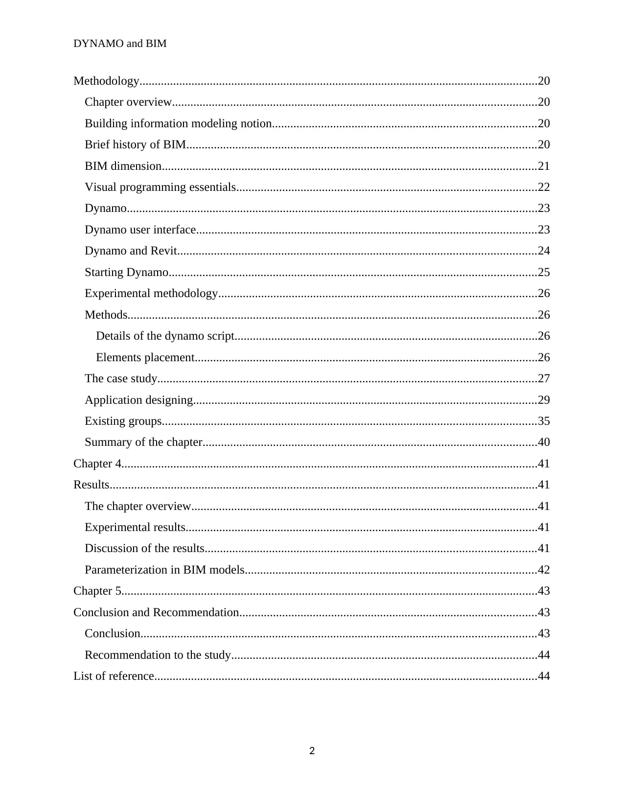
Methodology..................................................................................................................................20
Chapter overview.......................................................................................................................20
Building information modeling notion......................................................................................20
Brief history of BIM..................................................................................................................20
BIM dimension..........................................................................................................................21
Visual programming essentials..................................................................................................22
Dynamo......................................................................................................................................23
Dynamo user interface...............................................................................................................23
Dynamo and Revit.....................................................................................................................24
Starting Dynamo........................................................................................................................25
Experimental methodology........................................................................................................26
Methods......................................................................................................................................26
Details of the dynamo script...................................................................................................26
Elements placement................................................................................................................26
The case study............................................................................................................................27
Application designing................................................................................................................29
Existing groups..........................................................................................................................35
Summary of the chapter.............................................................................................................40
Chapter 4........................................................................................................................................41
Results............................................................................................................................................41
The chapter overview.................................................................................................................41
Experimental results...................................................................................................................41
Discussion of the results............................................................................................................41
Parameterization in BIM models...............................................................................................42
Chapter 5........................................................................................................................................43
Conclusion and Recommendation.................................................................................................43
Conclusion.................................................................................................................................43
Recommendation to the study....................................................................................................44
List of reference.............................................................................................................................44
2
DYNAMO and BIM
1. Introduction to the study
This chapter outlines the background, purpose, aims and limitations of this thesis.
1.1. Background
Currently in the world of architectural engineering, civil engineering and general construction, a
lot of emphasis is being given to time saving abilities; as such, engineers are under a lot of
pressure to save time while also delivering quality and precise work. In order to be able to
deliver the requisite standards of work at the shortest time possible, engineers need to apply a
wide range of methods and tools. Luckily enough due to the wonders of technology such
methods and tools are abundantly available (Singh, 2017). Over the last couple of years, several
construction companies have taken drastic efforts towards automating the work of their
architectural engineers and civil engineers and as such they have moved from hand drawings to
using computer software and BIM (Sacks & Pikas, 2013). The term BIM is an acronym for
Building information modelling which refers to an intelligent three dimensions model- founded
process that is usually used by architectural engineers and other professionals within the
construction and engineering fields to generate in-depth insights and tools for more efficient
planning, designing, constructs and perfect management of buildings and other forms of
infrastructure (Thomson, 2016) .
In recent times, the computing capabilities that are used to epitomize and analyse three-
dimensional models for buildings has improved drastically. The recent advent and evolution of
Building Information Modelling (BIM) has drastically transformed the Architectural,
Engineering and general construction fields from a drawing-based, Computer Aided Design
(CAD) sector to a fully-fledged management and transfer of information-based industry. The
increasing demand for proficiency and time saving during the process of constructing buildings
has stimulated the civil engineering, architectural and general construction industry towards the
full exploitation of the possibilities offered by the current tech-based advancements in the field
of structural design (Kranz, 2016). Various facets of structural design that include but are not
limited to geometrical simulations, performance analysis, mathematical optimization and even
the process of automation have begun to revolutionize the construction industry by inadvertently
arousing attention towards cutting edge techniques of modelling and testing building designs
inside virtual backgrounds (Chi & Wang, 2013). At the moment, the architectural industry
prompts the comprehension behind digital tech-based models by recognising three-dimensional
modelling not only as an exemplification of the actual building but also as a virtual model that is
used to test the actual state of affairs and reclaim crucial information that will aid in achieving
the requisite proficiency that is demanded for by all shareholders (Gamil, 2017). The more
enhanced and effectual these simulations are along the preliminary phases of design, the grander
the possibility for general realization of the project’s goals.
3
⊘ This is a preview!⊘
Do you want full access?
Subscribe today to unlock all pages.

Trusted by 1+ million students worldwide
DYNAMO and BIM
The progressive advancements in automation have led to the development of parametric design
which refers to the application of visual programming software which in essence, is directly
connected to the main BIM software (Borland, 2019). In attempts to achieve greater targets of
simulation reliability, efficiency and quality standards, parametric modelling has upheld itself
has one of the most effective tools. Parametric modelling facilitates the creation of malleable and
adjustable designs that can be pooled together with analysis, optimization and computation tools
(Garber, 2017). As such, it raises the overall efficiency of the building model. Furthermore, at
the moment these tools have the ability to integrate Building Information Modelling (BIM)
backgrounds, thereby creating room for more evolved and advanced applications. Although the
application of Virtual Programming software such as Dynamo, Grasshopper and Rhino in the
architectural, civil engineering and general construction fields is still at an all-time low, it is also
factual to argue that more and more investors in the aforementioned industry have become
conscious to the prospective advantages that they would reap by making use of Virtual
Programming software (Holzer, 2016). Moreover, the application of parametric modelling is
drastically increasing due to the fact that more and more countries are in the process of
establishing and enforcing new laws that require mandatory BIM application in particular sets of
projects (de Mattos Nascimentoa, 2016).
The application of visual programming software in BIM has played a very huge role in the
evolution of Building information modelling (BIM). The concept of “Visual Programming
Language” enables designers to construct very realistic relationships using graphical user
interfaces. Instead of developing programming ‘code’ from scratch, the users of visual
programming software can be able bring together conventional associations by connecting pre-
packaged nodes together to make up a complete traditional visual programming algorithm
(Meža, & Dolenc, 2015). Basically, this means that by using visual programming language, a
designer can be able to leverage computational concepts without necessarily having to write new
programming codes (Marcos, 2018). Computational design frameworks such as Visual
Programming software grant users the requisite resources and abilities for systematic automated
geometry creation, alteration and regulation of family parameters using external data and
information dissemination within a given platform and between different design platforms.
Computational design is a term used to refer to the ability to tie creative techniques of solving
problems with powerful and novel computational algorithms that have the ability to program,
mimic, script, regulate and produce various design solutions (Borges, 2018). In recent years,
computational Design has had a massive influence on Architectural endeavours. Design exploits,
be it hefty or minor, have begun to demand for new computational capabilities that allow
architectural engineers to customize their practices and perhaps, pursue cutting edge, innovative
design programs (Nemirovsky, 2017). Computations such as the use of Visual programming can
be leveraged for different for example, architectural engineering design, and the automation of
redundant production process and the construction of expressive form-generators. Irrespective of
the application of computation, it is very clear that designers need frameworks that can enable
4
Paraphrase This Document
Need a fresh take? Get an instant paraphrase of this document with our AI Paraphraser
DYNAMO and BIM
them to carry out their tasks with easily, more efficiently and within the shortest possible time
(Weinberg, 2019).
At the moment, Dynamo visual programming software is the leading software in the realm of
architectural design and as such is regarded as the leading driver of BIM evolution. Dynamo
visual programming software is an open source Add-in for Autodesk Revit and Vasari which
enables architectural designers to design conventional computation-based designs and
automation processes by making use of a node-based Visual Programming Interface (Cantrell,
and Mekies, 2018). Dynamo Visual Programming software gives architectural designers the
capabilities of sophisticated data manipulation, absolute geometric regulation and relational
frameworks all of which are impossible to achieve using traditional modelling interfaces. On top
of that, Dynamo Visual Programming software grants any architectural designer the surplus
advantage of the ability to leverage computational design workflows within the perspective of a
BIM background, as such; the user is gifted with the ability to construct conventional systems to
regulate Vasari families and constraints (Dutt and Swartz, 2016). In summary, it would be
correct to say that Dynamo Visual Programming software brings out a new essential means in
which architectural engineering designers can work with geometric information within Autodesk
Vasari and Revit towards creating regulatory frameworks for developing, arranging and
visualizing various geometrical concepts (Veloso and Scheeren, 2018). Basically, the Dynamo
Visual Programming framework enables architectural designers to come up with unique systems
and associations that have expanded individual perceptions on how BIM can be used to drive
design ideation.
In summary, it is correct to argue that design ideation through the use of Building Information
Modelling (BIM) is driven towards greater heights by parametric design tools which are based
on 3D CAD software such as Revit which serve to lengthen the margin of potential of BIM. On
top of that, tools like Revit create room for extensive customization capabilities via a set of add-
ins that extend BIM’s native capabilities. In most cases, this add-ins are technologically
advanced by third parties, thus creating room for the integration of performance simulations that
support several interoperability systems such as the Building Information Modelling (BIM)
system whose role is then to solve design complications using optimization techniques, and has
the capability to considerably automate design processes (Bazafkan, 2017). The integration of
Virtual Programming tools on BIM not only instils the Building Information Modelling (BIM)
system with great tractability but also the requisite malleability to be made use of on the
immense majority of projects from the architectural, civil engineering and general construction
industry.
1.2. Purpose
The purpose of this research is to illustrate the contribution of Dynamo Visual Programming
Software in the evolution of Building information modelling (BIM). As mentioned earlier,
construction companies are constantly striving towards reducing the time taken to complete their
projects while also seeking to improve the quality of their work. This endeavour has led to the
5
DYNAMO and BIM
development of new technologies, products and highly advanced ways of thinking within the
realm of architectural engineering and general construction. This thesis is meant to demonstrate
the contribution that Dynamo Visual Programming software has had on the evolution of BIM
through the aforementioned software’s ability to come up with cutting edge possibilities for
efficient and state of the art modelling and tabulation of BIM models.
1.3. Goal
This thesis aims to illustrate the ways in which Dynamo Visual Programming software has
contributed in the evolution of Building information Modelling (BIM). Despite the fact that
Visual Programming has been widely made use of in different fields, this paper acknowledges
that it has only recently developed significance in the 3D modelling programs of architectural,
civil engineering and general construction fields. Considering the fact that Visual Programming
software are relatively new in the building industry, the goal of this paper is to look at the
various aspects of Dynamo Visual Programming Software that make it a very vital contributor to
the evolution of Building Information Modelling (BIM). Currently, there are numerous
construction companies operating within the construction industry and they use a wide variety of
software throughout the construction process. There is a wide variety of software which could be
used for modelling, energy calculations and calculations of load paths. This research is not meant
to downplay the role of other Visual Programming software but to undoubtedly bring out the role
that Dynamo Visual Programming software plays in the evolution of BIM compared to other
Visual Programming software such as, Grasshopper Visual Programming software and Rhino
Visual Programming software. The analytical applications that are materialized in this thesis
help to demonstrate the enormous possibilities that Dynamo Visual Programming software has
towards completing and improving Building Information Modelling (BIM) as a result of the fact
that it includes parametric geometries and works with Rivets which is basically, the foremost
BIM software.
1.4. Limitations
The exploration of the contribution of Dynamo Visual Programming software in the evolution of
Building Information Modelling (BIM) will be the main area of concern for this research.
Although Dynamo Visual Programming Software cannot be the only Visual Programming
software that is credited for the evolution of BIM, this thesis aims to limit itself to the Dynamo
Visual Programming software purview. The script of the research will be limited to the
aforementioned goals of the thesis. Putting the topic at hand into consideration, several case
studies can be necessary however; this thesis will comprise the generalization of the key aspects
of the Dynamo Visual Programming software with regard to BIM and analysis of Dynamo
Visual Programming elements that are perceived to drive the evolution of Building Information
Modelling (BIM).
2. LITERATURE REVIEW
In this chapter, the theoretical framework of the key aspects behind this thesis is described and
an in-depth explanation is given as to why the aforementioned aspects are important to this work.
6
⊘ This is a preview!⊘
Do you want full access?
Subscribe today to unlock all pages.

Trusted by 1+ million students worldwide
DYNAMO and BIM
Furthermore, this chapter will take an in-depth look into the dynamo Visual Programming
software and its relationship with Revit and BIM as a whole.
2.1. Definition and history of Building Information Modelling (BIM)
Building Information Modelling (BIM) is a term used to refer to the procedure that is used to
create a three-dimensional model platform that lets design professionals such as architects and
civil engineering consultants to partake in the design process on an immediate and
multidisciplinary basis (Mayo and Smith, 2018). The concept of BIM is relatively new in the
arena of architecture, civil engineering and general construction but it is true to say that at the
moment, building information modelling (BIM) has been attracting a lot of attention in the
architectural, civil engineering and general construction fields. Within the last half of the decade
alone, the world has been spouting about BIM in the architectural, building and construction
fields so much that most countries are currently in the process of enacting laws and regulations
that will make the application of BIM compulsory in certain projects (Sieffert & Daudon, 2014).
BIM has been the trending catchphrase in the realm of architecture, civil engineering and general
construction and though it may appear to be new to most people, in actual sense the concepts and
technologies behind BIM have been in existence and constantly evolving for more than five
decades MANJUNATHA, 2019).
In retrospect, the idea behind the existence of BIM cannot be credited to a single individual
mainly because it has a very rich history of origination from various regions in the world
including the United States of America (USA), Central and Northern Europe and across the seas
to Japan which is situated in Asia. Basically, the concept of BIM has been in existence since the
advent of the 1970s (De Wilde and Garrigós, 2019). However, it was not until the middle of the
1980’s that the term “building model” was placed in print by a man known as Simon Ruffle.
Nearly a decade later, the term “Building Information Model” was coined and published by G.A.
Van Nederveen alongside a colleague known as F. P. Tolman in 1992. After the term ‘BIM’ was
coined, its development and evolution began officially but no significant leaps were taken until
construction and architectural companies changed their design systems from hand drawings to
AutoCAD digital drawings. AutoCAD’s 2D drawings are mostly similar to hand drawings but
the only difference is that they are done faster. The next step in the evolution of building design
was the introduction of BIM (Nikolic, & Messner, 2011). By making use of a wide variety of
computer software such as Revit, Tekla structures and numerous other types of software, the
users can be able to come up with various distinct shapes and designs within the software’s
framework in a very easy manner. From the 3D models that are generated by the software, 2D
printed drawings can then be acquired. Looking back at the history of BIM, one would
fascinatingly notice that a huge chunk of its history is entangled with the drama of the Cold War.
In summary, it would be true to argue that all these pleasing tales about the innovation and the
evolution of BIM come down to the sprint towards coming up with the most flawless collective
solution that would upset the 2D CAD work flows.
7
Paraphrase This Document
Need a fresh take? Get an instant paraphrase of this document with our AI Paraphraser
DYNAMO and BIM
2.1.1. The current state of Building Information Modelling (BIM)
Currently, the most idyllic BIM software has capability to epitomize the actual physical and
inherent features of a building as an object-focused design that is linked to a particular database.
Most modern Building Information Models have the ability to render contraptions, enhance
property specific categorization and program specific backgrounds from which designers can be
able to build model components. Furthermore, modern BIM models are mostly three-
dimensional in nature with orthographic two-dimensional plans that are made up of sectional and
elevation outlooks (Shigaki, 2016). During the course of infrastructural or architectural project
development, project representations and variations are congruently adjusted with each change in
the design. Building information models can be designed within software that may or may not be
parametric in nature but it is important to note that the best Building Information Models are
those that are designed within parametric software frameworks. The most recent versions of
BIM have the capability to handle enormous volumes of information, hence the need for
parametric software. In its current form, BIM can be able to make use of a wide variety of files
key among them being the Industry Foundation Classes (IFC) files (Johansen and Kjærvik,
2018). Industry Foundation Classes refers to open and neutral data file formats that can be
opened through various platforms such as Revit. It is also important to note that IFCs exist on a
read-only format and therefore, cannot be edited under any circumstances whatsoever (Becerik-
Gerber, & Ku, 2011). However, despite the fact that IFCs cannot be edited, they can be
influenced on a certain level using Dynamo Visual Programming Software.
An in-depth look into literature concerned with Building Information models reveals that
parametric software are vital for the ultimate efficiency and quality of any given BIM system.
Parametric can be defined as an algorithm-based method that gives room for the manifestation of
parameters and regulations that, collectively serve to delineate, encrypt and elucidate the
relationship between the intention of the model and the model’s subjective response (Wang,
2014). The role of parametric software in regards to BIM is to provide capabilities for the
generation of constraint features which include the elevation of a horizontal base, which then can
be connected to the elevation of a particular set of walls which are parametrically placed in tune
with each other thereby, forming a geometry-linked dynamic database design. The evolution of
BIM as a result of its integration with parametric software introduced a cutting-edge solution to
the challenge of absence of computable raw data during the design stage of any architectural,
civil engineering or general construction project.
The introduction of parametric modelling in BIM created the much needed room for the
architectural, civil engineering and general construction industry to change project
representations at several scales and across disjointed sketch sheets thereby, reducing in a major
proportion the long and tiresome hours that were necessary for manual redrafting of the sketches
(Högberg and SPARGREN, 2017). The application of computer-based technology in the design
sector led to extensive automation of time consuming tasks in all disciplines, thereby largely
improving general yield. During its initial discovery stages, BIM was more of a grammatical
8
DYNAMO and BIM
term than actual useful technology. As time went by, BIM evolved and computer limitations and
weird user interfaces for BIM platforms ended up with 2D line drawing programs such as
AutoCAD (Nawari, 2012). It took quite a significant amount of time to incorporate
computability in design modelling.
2.1.2. Conditions to be met so as to qualify as a BIM model
Currently, there are four conditions that must be met in order to refer to a model as BIM and they
include:
Management of information is carried out basing on one or more object-oriented models.
Features are linked to the objects in the models and are applied extensively.
The bits and pieces that make up the model are associated to each other.
A wide variety of views of information can be formed from the same model.
2.1.3. The value of BIM in the context of building design
It is a universally accepted fact that it is extremely expensive to put up buildings. Furthermore,
there is a deep rooted consensus that what makes the construction of the aforementioned
buildings that much expensive is the cost that comes with the design stage which is actually more
expensive than it should just fully be. Thanks to the invention of Building information models,
professionals in the building industry have found it much easier to come up with building models
within a computer. The models are digital in nature therefore making the computer-based models
of building more convenient and much cheaper than hand drawings which were used before BIM
was introduced to the building industry. The process of coming up with a building is made up of
an entire lifespan of the building in question ranging from its idea, design stage, construction,
serviceable life, remodelling and perhaps its disposal and it is important to note that BIM can be
very instrumental in all parts of the aforementioned stages of a building’s lifecycle (Madanayake
and Egbu, 2017).
2.2. Autodesk Revit
Autodesk Revit is essentially a building information modelling software that is used by a wide
variety of design professionals ranging from building architects, backdrop architects, structural
engineering practitioners, mechanical engineers, electrical engineers and plumbing engineers,
general designers and building contractors among others (Li, 2018). Revit Autodesk 3D
modelling software allows its users to design an extensive variety of aspects of a structure in a
manner that the designer or the architect can be able to envisage the whole structure before
transforming the different sections of the design into a drawing on a hard copy. After generating
a 3dimensional design it is then printed onto a paper in 2 dimensional formats which the
contractor can later use during the actual construction stage. Basically, the role of Revit is to
design various structures and organize their components in three-dimensional formats, interpret
the model with two-dimensional drafting features and access buildings’ raw data from the
building design's database (Sacks and Teicholz, 2018).
9
⊘ This is a preview!⊘
Do you want full access?
Subscribe today to unlock all pages.

Trusted by 1+ million students worldwide
DYNAMO and BIM
2.2.1. The History of Revit
The story of Revit began in 1997 the month of October with the foundation of Charles River
Software Company by Leonid Raiz and Irwin Jungreis in Newton the state of Massachusetts,
United States of America. Leonid Raiz and Irwin Jungreis were the main developers of cutting-
edge Engineering software for mechanical modelling and their goal in forming Charles River
Software Company was to transfer the power of parametric design to the architectural, civil
engineering and general construction industry (Yadav and Kanade, 2018). Leonid and Irwin
adequately utilized the funding that they received from venture capitalists known as Atlas
Venture and North Bridge Venture Partners towards hiring a very robust team of software
developers and architects. The collective team of specialist began their jobs by developing Revit
in C++ on window’s Microsoft platform. By the year 1999, they had hired a company CEO
known as Dave Lemont and also recruited two board members known as Jon Hirschtick and Arol
Wolford who were founders of Solidworks and CMD group respectively (.
From its onset, the intended purpose of Revit was to give room for various professionals such as
architects and building practitioners to create models and representations of an actual building by
coming up with parametric three-dimensional designs that are made up of non-geometric and
geometric models and construction raw data which are also referred to as Building Information
Modelling (BIM). At that particular point in time, a wide variety of other software packages for
example, ArchiCAD and Reflex had already been introduced into the market. ArchiCAD and
Reflex were able to generate 3D models and grant their users the ability to regulate individual
features through various parametric components. The two main variations between the
functionality of Revit and that of ArchiCAD and Reflex at that particular point in time were that
in Revit were that its users were able to create parametric components in a graphical ‘family
editor’ format instead of using a programming language. As such, the design adopted the
association between various components, perceptions and interpretations in a manner that will
enable the system to automatically disseminate a change in one element so as to maintain the
consistency of the model (Imtaar, 2016). For instance, if one were to move one wall the rest of
the adjacent walls will be automatically updated such that the model will remain interlinked and
all the relevant documentations will remain coordinated. Also, the concept of dual directional
association amongst various parametric components, perceptions and interpretations was one of
the main distinguishing features between Revit releases and other related software packages at
that particular point in time. The ease of making a wide variety of changes during the design
stages of the structures drove the company towards adopting the name Revit which is basically a
contraction of Revise Instantly (Takim & Nawawi, 2013). A parametric change transmission
engine is found at the heart of Revit and was mostly relied upon as a cutting-edge technological,
perspective driven parametric system that was found to be more scalable compared to the
change-based, history driven parametric systems that were applied in mechanical CAD software.
As such, the term ‘Parametric Building Model’ was coined to mirror the fact that the ability to
alter different parameters led to the subsequent evolution of the entire building model alongside
related documentations (Danner, 2016).
10
Paraphrase This Document
Need a fresh take? Get an instant paraphrase of this document with our AI Paraphraser
DYNAMO and BIM
As a result of several advancements in Revit, the Charles River Company Changed its name to
the Revit Technology Corporation in January in 2000 and subsequently, Revit version 1.0 was
released on April 5, 2000. Since its initial introduction to the market it progressed rapidly from
releasing version 2.0 in August 2000, 3.0 in October 2000, 3.1 in February 2001, 4.0 in the
month of June 2001 and 4.0 in January 2002. During its initial stages, the Revit was only
available in the market as a monthly rental with no permanent purchase option. At the time,
licencing of software was under the full management of a fully automated process, an innovation
which at that particular moment, when human involvement and manual dissemination of
authorization codes was the only known means of purchasing other similar types of design
software packages (Jang, & Kim, 2011). In 2002, a company known as Autodesk which is well
known for the renowned AutoCAD line of products bought and took absolute control of Revit
Technology Corporation at a cost of 133 million US dollars. After Autodesk took over the
ownership rights of Revit in 2002, they embarked on serious and extensive research, expansion
and enhancement of Revit software capabilities. Several years down the line, Autodesk has come
up with numerous versions of Revit starting in the year 2005 when they introduced Revit
Structure to 2006 when they introduced Revit MEP. It is important to note that following the
2006 release, Autodesk renamed Revit Building to Revit Architecture. In 2012, Autodesk
introduced Revit LT which was then the latest version of Revit in the Market. Revit LT was a lite
version of Revit which lacked a number of features for example, rendering and multi-user
environments (Fakhrutdinov, 2018). However, since the introduction of Revit 2013, the various
classes of Revit were put together into one software package which is simply referred to as
Revit. Currently as a result of their Revit platform, Autodesk is a key player in the market of
BIM and is in competition with major firms such as Nemetscheck who are the creators of
ArchiCAD and AllPlan alongside Vector works and Gehry Technologies.
2.2.2. Configurations in Revit
The Revit hierarchy basically refers to an already existent order of classifications under which all
components inside the Revit software fall. Each and every component in Revit has to fall under a
specific grouping. The list of groupings is permanent in the software and therefore cannot be
formed nor erased (Garcia, 2019). User variations of complete groupings are normally associated
to graphical forms. It is important to note that everything that is part of a Revit Model is
classified as an object. These objects include 3D components, 2D components, views and sheets.
Simultaneously, any time of object answers to an organized hierarchy who role is to put together
various pieces of data into models. Basically, Revit makes use of a variety of elements while
executing different projects. These elements include:
1. Model elements
Model elements epitomize the authentic 3D geometry of the building and display in relevant
outlooks of the model. Generally speaking, there three known types of model elements namely:
11
DYNAMO and BIM
i. Hosts
Hosts are largely assembled at the construction location. They are system families in Revit and
are referred to as “Host” elements mainly because they habitually host other design elements.
Examples of hosts include:
Walls and ceilings
Structural walls and roofs
ii. Model components
Model components refer to all the other types of elements found within the building design. They
include windows, doors, cabinets, beams, braces, and mechanical columns.
iii. Datums
Datums are the key references found within the model, particularly the “Levels”, as a result of
the fact that a major chunk of the elemental composition of the models are attached or referred to
the aforementioned levels. Datums are exceptional mainly due to the fact that even though they
are presented in outlook as 2D elements, and are not displayed in 3D views, they are in fact
three-dimensional elements. Their purpose is to aid in defining the context of the project as in,
coming up with grids, levels and reference planes.
2. View-specific elements
View-Specific elements exhibit only in the views in which they are positioned and their role is
to aid in describing or documenting the model. Essentially, there are 2 types of view-specific
elements namely:
i. Annotation elements
Annotation elements refer to sets of 2D components whose role is to document the model and
maintain the model’s scale on paper. Annotation elements include dimensions, tags and keynotes
among others.
ii. Details
Details are two dimensional bits and pieces that provide in-depth specifics about the building
model in a particular view. Details are model-scaled and they include detail lines, filled regions
and other 2D detail components.
3. Views
Views are components that give room for the ultimate access and subsequent documentation of
all the raw data that are contained within the model. Views play the role of connecting model
objects and view-specific objects. Let´s consider a situation where Model objects purely exist
within the model but on the other hand view specific objects exist solitarily in the views within
which in which they are positioned, the role of the views will be to show the information
12
⊘ This is a preview!⊘
Do you want full access?
Subscribe today to unlock all pages.

Trusted by 1+ million students worldwide
1 out of 50
Your All-in-One AI-Powered Toolkit for Academic Success.
+13062052269
info@desklib.com
Available 24*7 on WhatsApp / Email
![[object Object]](/_next/static/media/star-bottom.7253800d.svg)
Unlock your academic potential
Copyright © 2020–2026 A2Z Services. All Rights Reserved. Developed and managed by ZUCOL.