Earthquake Resistant Construction: Nepal Element Optimization
VerifiedAdded on 2021/04/24
|18
|4373
|67
Report
AI Summary
This research paper validates and optimizes dimensions, sizes, and details for horizontal and vertical bands in earthquake-resistant construction, specifically for Nepal. The study, based on the Smart Shelter Foundation's projects, investigates the performance of horizontal bands (plinth, lintel, roof, and gable) and vertical reinforcement in various masonry types (concrete block, brick, and rubble stone). The report analyzes existing practices, including recommendations from IS: 4226:1996, and presents a matrix for optimum dimensions, steel reinforcement, and details based on seismic hazard levels and construction types. The research also covers the role of roof diaphragms and the protection and maintenance of reinforcement elements. The goal is to provide clear guidelines for improving the seismic resistance of buildings in Nepal, though the report does not include lab testing data, but it presents the outcome of the experimental setup with recommendations for the optimized details, dimensions, sizes, and numbers of the horizontal and vertical bands for constructions in Nepal.
Earthquakes Resistance Construction 1
OPTIMIZATION OF SPECIFIC ELEMENTS WITHIN EARTHQUAKE RESISTANT
CONSTRUCTION
A Research Paper on Earthquakes By
Student’s Name
Name of the Professor
Institutional Affiliation
City/State
Year/Month/Day
OPTIMIZATION OF SPECIFIC ELEMENTS WITHIN EARTHQUAKE RESISTANT
CONSTRUCTION
A Research Paper on Earthquakes By
Student’s Name
Name of the Professor
Institutional Affiliation
City/State
Year/Month/Day
Paraphrase This Document
Need a fresh take? Get an instant paraphrase of this document with our AI Paraphraser
Earthquakes Resistance Construction 2
INTRODUCTION
Purpose
This research paper is about validation and optimization of dimensions, sizes, number, and
details for the most commonly used vertical and horizontal bands for construction in Nepal.
The research seeks to optimize the specific elements within the earthquake resistant
construction by improving the overall strength and stability of the horizontal bands and
vertical reinforcement. Through testing laboratory, the team will determine the amount of
seismic force that these types of constructions can withstand.
Background
Between 2007 and 2012, the Smart Shelter Foundation constructed 15 schools that are
earthquake resistant in the mountainous region of Kaski, Nepal. Some of the structures were
constructed with hollow concrete blocks while others with rubble stone masonry. The
horizontal concrete bands were incorporated into the walls at numerous levels to improve
their overall strength and stability, and stones were incorporated into the walls for better
bonding. Good construction and design meant by the Smart Shelter Foundation survived the
heavy earthquakes that struck the area in 2015 April without any substantial destruction,
while numerous houses surrounding including the whole of the villages were flattened.
It is normally accepted that horizontal bands have a positive impacts on the seismic
resistance of the structure. Assessment after the earthquakes indicates that structures with
horizontal ties can sustain the seismic forces much better compared to the buildings without
these specifications. It has been noted that block and brick walls need vertical reinforcement
so as to strengthen the critical connections and to prevent shear cracks.
Earthquakes Resistance Construction 3
Scope
This research seeks to fully cover the collaboration and combination of vertical and
horizontal steel bars and provide clear recommendations for their use in cement block
masonry, brick and block, and rubble stone masonry. However, this report will not cover the
process of lab testing concerning the amount of seismic force that these types of constructions
can sustain. The report just presents the outcome of the experimental setup with
recommendations for the optimized details, dimensions, sizes, and numbers of the horizontal
and vertical bands for constructions in Nepal.
RESEARCH AREA 1
STATUS
This task seeks to provide description of the performance of horizontal bands, describe things
that have been accomplished, and difficulties encountered. There is analysis, testing and
recommendations of diverse types of horizontal reinforcement and their details such as rods,
lacing, and bands. The types and solutions of horizontal reinforcements are also considered
together with their seismic behaviour. This last task for this section is the development of a
matrix for optimum dimensions of the beam, optimum steel reinforcement, and correct details
for different types of constructions and for different levels of seismic hazards.
Performance of Horizontal Bands
The horizontal band is a method of reinforcing masonry construction through the
provision of higher tensile strength. This is effective in regions where two elements of the
structure of a building meet, hence a connection is formed all together and they would behave
a single unit. Horizontal bands can also be referred to as seismic bands which entail
reinforced concrete running flat in the whole of the internal and external masonry wall
elements. The horizontal bands can be applied in the following levels; at the ceiling levels, at
⊘ This is a preview!⊘
Do you want full access?
Subscribe today to unlock all pages.
Trusted by 1+ million students worldwide
Earthquakes Resistance Construction 4
the levels of lintels such as windows and doors, and at the plinth of the construction (Aguilar,
2011).
The requirement of horizontal bands in the level of the roof is not necessary in case
the roofs are reinforced masonry slab or reinforced concrete units provided that they possess
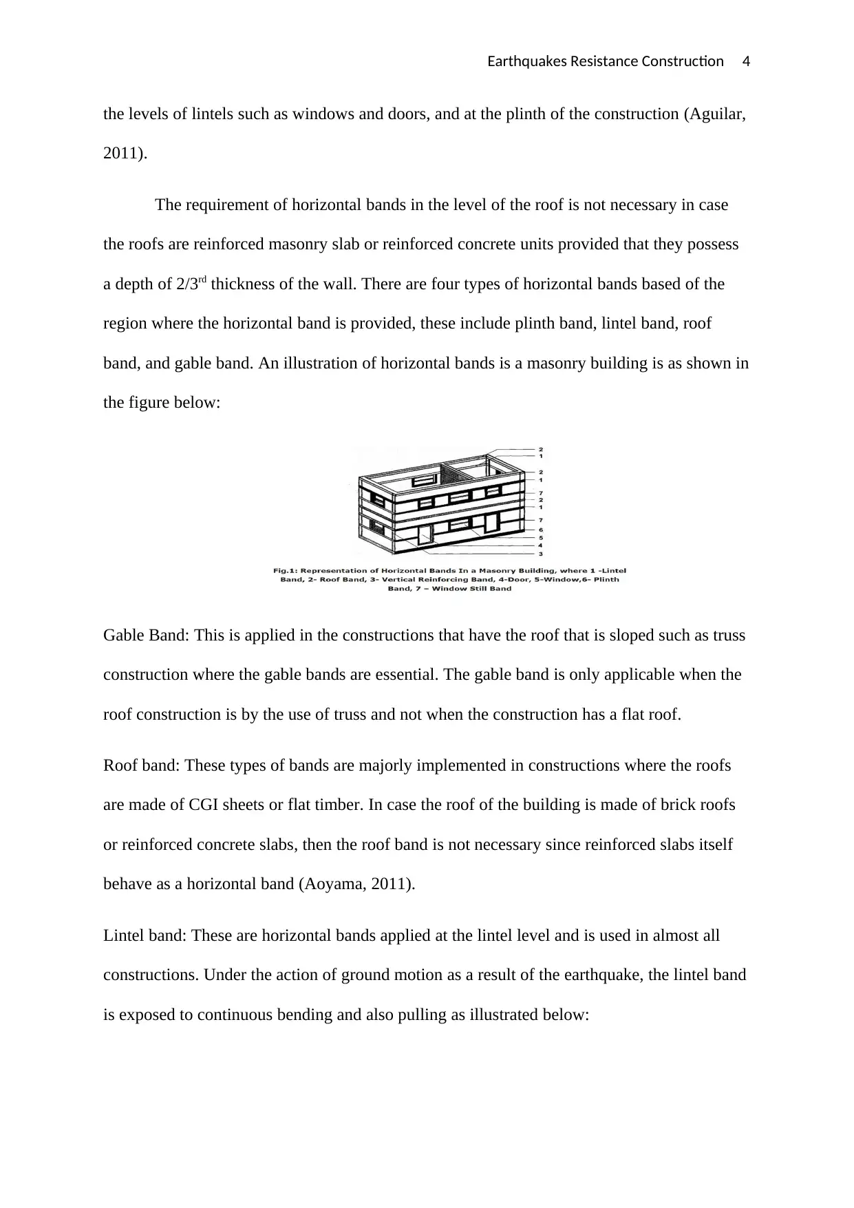
a depth of 2/3rd thickness of the wall. There are four types of horizontal bands based of the
region where the horizontal band is provided, these include plinth band, lintel band, roof
band, and gable band. An illustration of horizontal bands is a masonry building is as shown in
the figure below:
Gable Band: This is applied in the constructions that have the roof that is sloped such as truss
construction where the gable bands are essential. The gable band is only applicable when the
roof construction is by the use of truss and not when the construction has a flat roof.
Roof band: These types of bands are majorly implemented in constructions where the roofs
are made of CGI sheets or flat timber. In case the roof of the building is made of brick roofs
or reinforced concrete slabs, then the roof band is not necessary since reinforced slabs itself
behave as a horizontal band (Aoyama, 2011).
Lintel band: These are horizontal bands applied at the lintel level and is used in almost all
constructions. Under the action of ground motion as a result of the earthquake, the lintel band
is exposed to continuous bending and also pulling as illustrated below:
the levels of lintels such as windows and doors, and at the plinth of the construction (Aguilar,
2011).
The requirement of horizontal bands in the level of the roof is not necessary in case
the roofs are reinforced masonry slab or reinforced concrete units provided that they possess
a depth of 2/3rd thickness of the wall. There are four types of horizontal bands based of the
region where the horizontal band is provided, these include plinth band, lintel band, roof
band, and gable band. An illustration of horizontal bands is a masonry building is as shown in
the figure below:
Gable Band: This is applied in the constructions that have the roof that is sloped such as truss
construction where the gable bands are essential. The gable band is only applicable when the
roof construction is by the use of truss and not when the construction has a flat roof.
Roof band: These types of bands are majorly implemented in constructions where the roofs
are made of CGI sheets or flat timber. In case the roof of the building is made of brick roofs
or reinforced concrete slabs, then the roof band is not necessary since reinforced slabs itself
behave as a horizontal band (Aoyama, 2011).
Lintel band: These are horizontal bands applied at the lintel level and is used in almost all
constructions. Under the action of ground motion as a result of the earthquake, the lintel band
is exposed to continuous bending and also pulling as illustrated below:
Paraphrase This Document
Need a fresh take? Get an instant paraphrase of this document with our AI Paraphraser
Earthquakes Resistance Construction 5
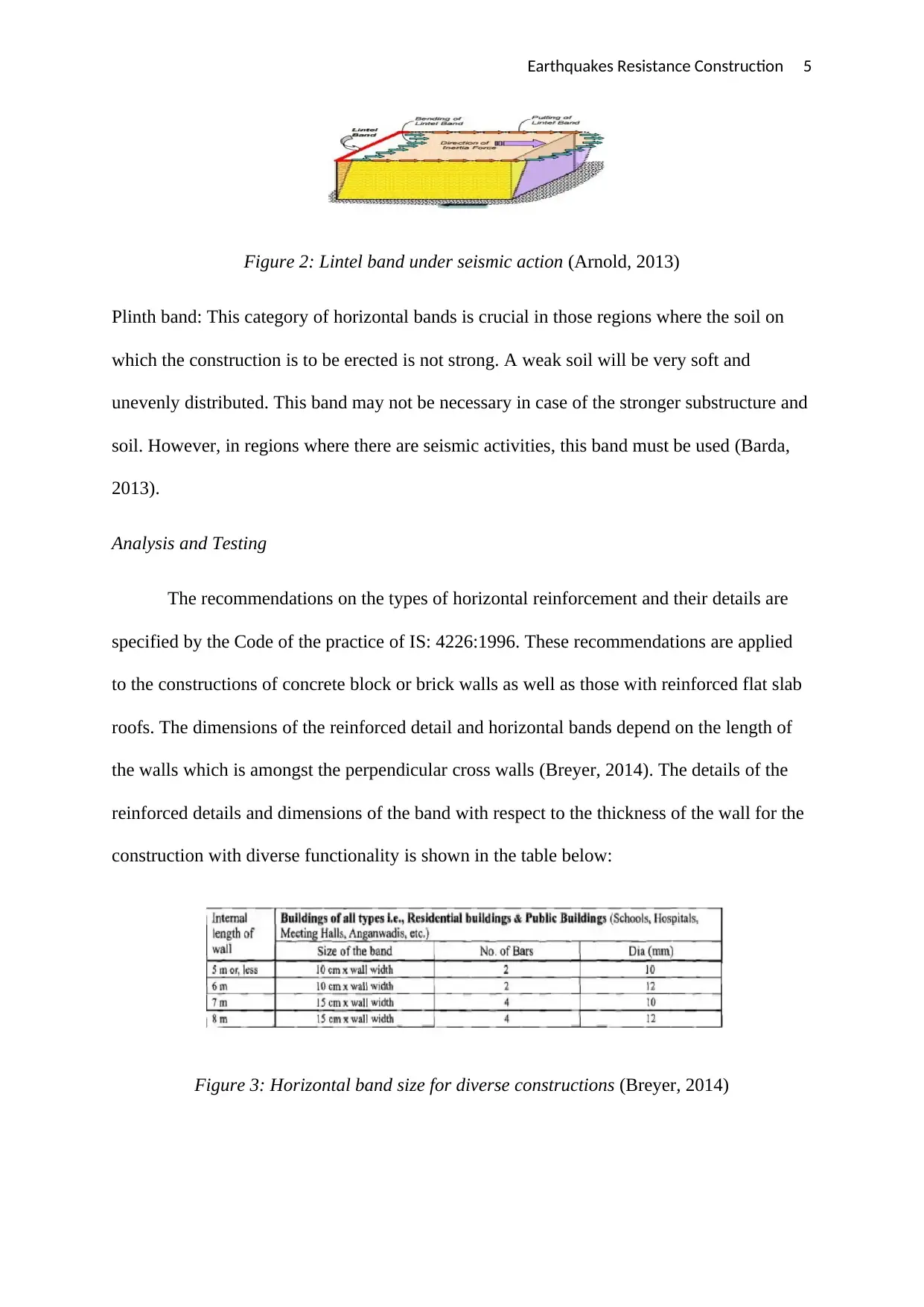
Figure 2: Lintel band under seismic action (Arnold, 2013)
Plinth band: This category of horizontal bands is crucial in those regions where the soil on
which the construction is to be erected is not strong. A weak soil will be very soft and
unevenly distributed. This band may not be necessary in case of the stronger substructure and
soil. However, in regions where there are seismic activities, this band must be used (Barda,
2013).
Analysis and Testing
The recommendations on the types of horizontal reinforcement and their details are
specified by the Code of the practice of IS: 4226:1996. These recommendations are applied
to the constructions of concrete block or brick walls as well as those with reinforced flat slab
roofs. The dimensions of the reinforced detail and horizontal bands depend on the length of
the walls which is amongst the perpendicular cross walls (Breyer, 2014). The details of the
reinforced details and dimensions of the band with respect to the thickness of the wall for the
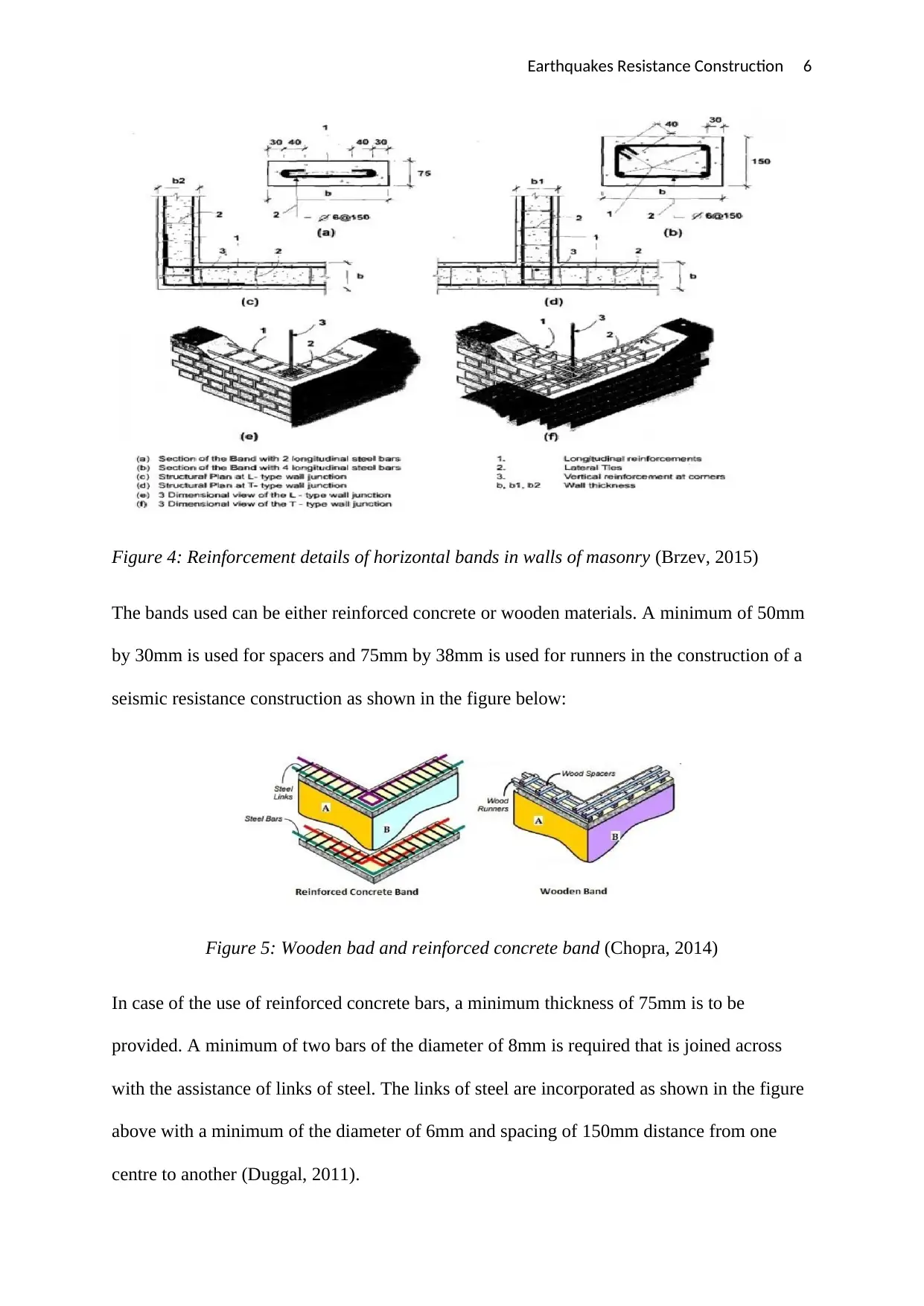
construction with diverse functionality is shown in the table below:
Figure 3: Horizontal band size for diverse constructions (Breyer, 2014)
Figure 2: Lintel band under seismic action (Arnold, 2013)
Plinth band: This category of horizontal bands is crucial in those regions where the soil on
which the construction is to be erected is not strong. A weak soil will be very soft and
unevenly distributed. This band may not be necessary in case of the stronger substructure and
soil. However, in regions where there are seismic activities, this band must be used (Barda,
2013).
Analysis and Testing
The recommendations on the types of horizontal reinforcement and their details are
specified by the Code of the practice of IS: 4226:1996. These recommendations are applied
to the constructions of concrete block or brick walls as well as those with reinforced flat slab
roofs. The dimensions of the reinforced detail and horizontal bands depend on the length of
the walls which is amongst the perpendicular cross walls (Breyer, 2014). The details of the
reinforced details and dimensions of the band with respect to the thickness of the wall for the
construction with diverse functionality is shown in the table below:
Figure 3: Horizontal band size for diverse constructions (Breyer, 2014)
Earthquakes Resistance Construction 6
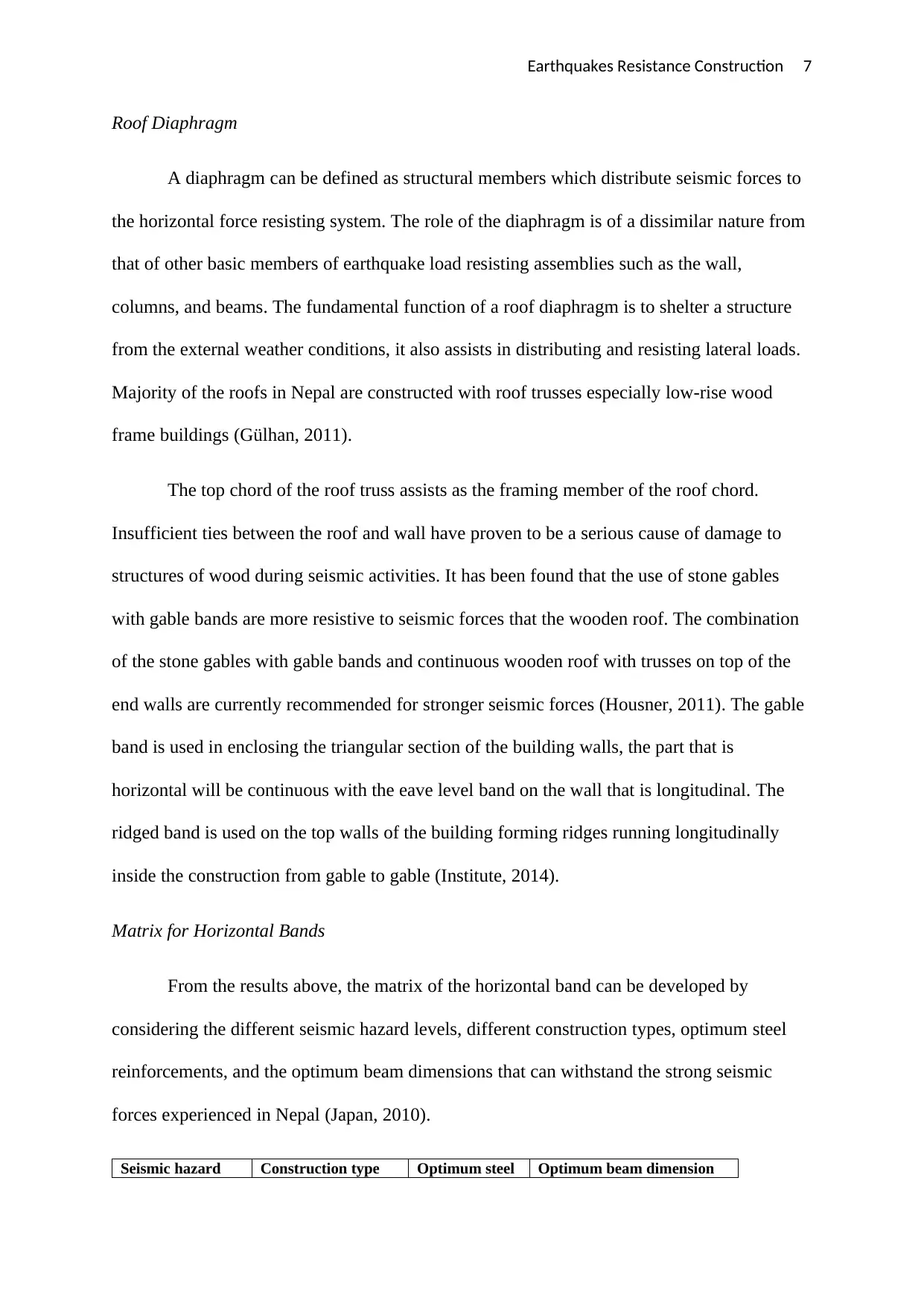
Figure 4: Reinforcement details of horizontal bands in walls of masonry (Brzev, 2015)
The bands used can be either reinforced concrete or wooden materials. A minimum of 50mm
by 30mm is used for spacers and 75mm by 38mm is used for runners in the construction of a
seismic resistance construction as shown in the figure below:
Figure 5: Wooden bad and reinforced concrete band (Chopra, 2014)
In case of the use of reinforced concrete bars, a minimum thickness of 75mm is to be
provided. A minimum of two bars of the diameter of 8mm is required that is joined across
with the assistance of links of steel. The links of steel are incorporated as shown in the figure
above with a minimum of the diameter of 6mm and spacing of 150mm distance from one
centre to another (Duggal, 2011).
⊘ This is a preview!⊘
Do you want full access?
Subscribe today to unlock all pages.
Trusted by 1+ million students worldwide
Earthquakes Resistance Construction 7
Roof Diaphragm
A diaphragm can be defined as structural members which distribute seismic forces to
the horizontal force resisting system. The role of the diaphragm is of a dissimilar nature from
that of other basic members of earthquake load resisting assemblies such as the wall,
columns, and beams. The fundamental function of a roof diaphragm is to shelter a structure
from the external weather conditions, it also assists in distributing and resisting lateral loads.
Majority of the roofs in Nepal are constructed with roof trusses especially low-rise wood
frame buildings (Gülhan, 2011).
The top chord of the roof truss assists as the framing member of the roof chord.
Insufficient ties between the roof and wall have proven to be a serious cause of damage to
structures of wood during seismic activities. It has been found that the use of stone gables
with gable bands are more resistive to seismic forces that the wooden roof. The combination
of the stone gables with gable bands and continuous wooden roof with trusses on top of the
end walls are currently recommended for stronger seismic forces (Housner, 2011). The gable
band is used in enclosing the triangular section of the building walls, the part that is
horizontal will be continuous with the eave level band on the wall that is longitudinal. The
ridged band is used on the top walls of the building forming ridges running longitudinally
inside the construction from gable to gable (Institute, 2014).
Matrix for Horizontal Bands
From the results above, the matrix of the horizontal band can be developed by
considering the different seismic hazard levels, different construction types, optimum steel
reinforcements, and the optimum beam dimensions that can withstand the strong seismic
forces experienced in Nepal (Japan, 2010).
Seismic hazard Construction type Optimum steel Optimum beam dimension
Paraphrase This Document
Need a fresh take? Get an instant paraphrase of this document with our AI Paraphraser
Earthquakes Resistance Construction 8
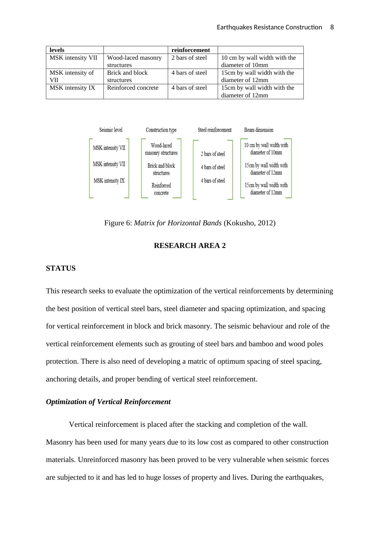
levels reinforcement
MSK intensity VII Wood-laced masonry
structures
2 bars of steel 10 cm by wall width with the
diameter of 10mm
MSK intensity of
VII
Brick and block
structures
4 bars of steel 15cm by wall width with the
diameter of 12mm
MSK intensity IX Reinforced concrete 4 bars of steel 15cm by wall width with the
diameter of 12mm
Figure 6: Matrix for Horizontal Bands (Kokusho, 2012)
RESEARCH AREA 2
STATUS
This research seeks to evaluate the optimization of the vertical reinforcements by determining
the best position of vertical steel bars, steel diameter and spacing optimization, and spacing
for vertical reinforcement in block and brick masonry. The seismic behaviour and role of the
vertical reinforcement elements such as grouting of steel bars and bamboo and wood poles
protection. There is also need of developing a matric of optimum spacing of steel spacing,
anchoring details, and proper bending of vertical steel reinforcement.
Optimization of Vertical Reinforcement
Vertical reinforcement is placed after the stacking and completion of the wall.
Masonry has been used for many years due to its low cost as compared to other construction
materials. Unreinforced masonry has been proved to be very vulnerable when seismic forces
are subjected to it and has led to huge losses of property and lives. During the earthquakes,
Earthquakes Resistance Construction 9
the surface of the ground moves in every direction. The damages of the construction are as a
result of the lateral movement which is opposite to the lateral loads being applied (Correia,
2012).
The bars for vertical reinforcement are slid into position from the top and weaved into
horizontal reinforcement and safeguarded into correct location depending on the specs and
plans of the project. The bars for reinforcement have been embedded in brick masonry at the
corners of every room and the section of the openings of doors for earthquake safety zone V.
Windows opening in the dimensions larger than 60 cm will also require bars for
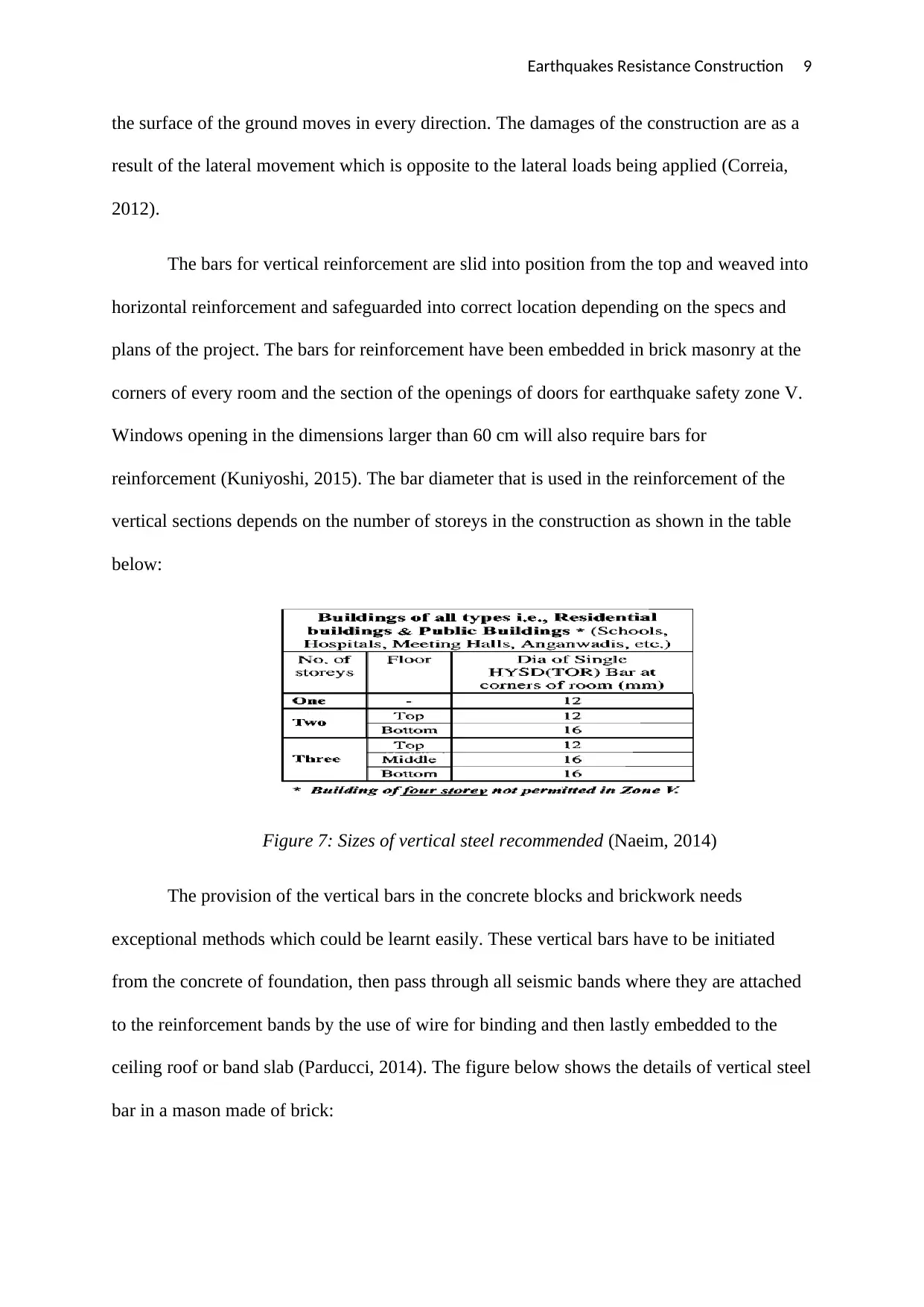
reinforcement (Kuniyoshi, 2015). The bar diameter that is used in the reinforcement of the
vertical sections depends on the number of storeys in the construction as shown in the table
below:
Figure 7: Sizes of vertical steel recommended (Naeim, 2014)
The provision of the vertical bars in the concrete blocks and brickwork needs
exceptional methods which could be learnt easily. These vertical bars have to be initiated
from the concrete of foundation, then pass through all seismic bands where they are attached
to the reinforcement bands by the use of wire for binding and then lastly embedded to the
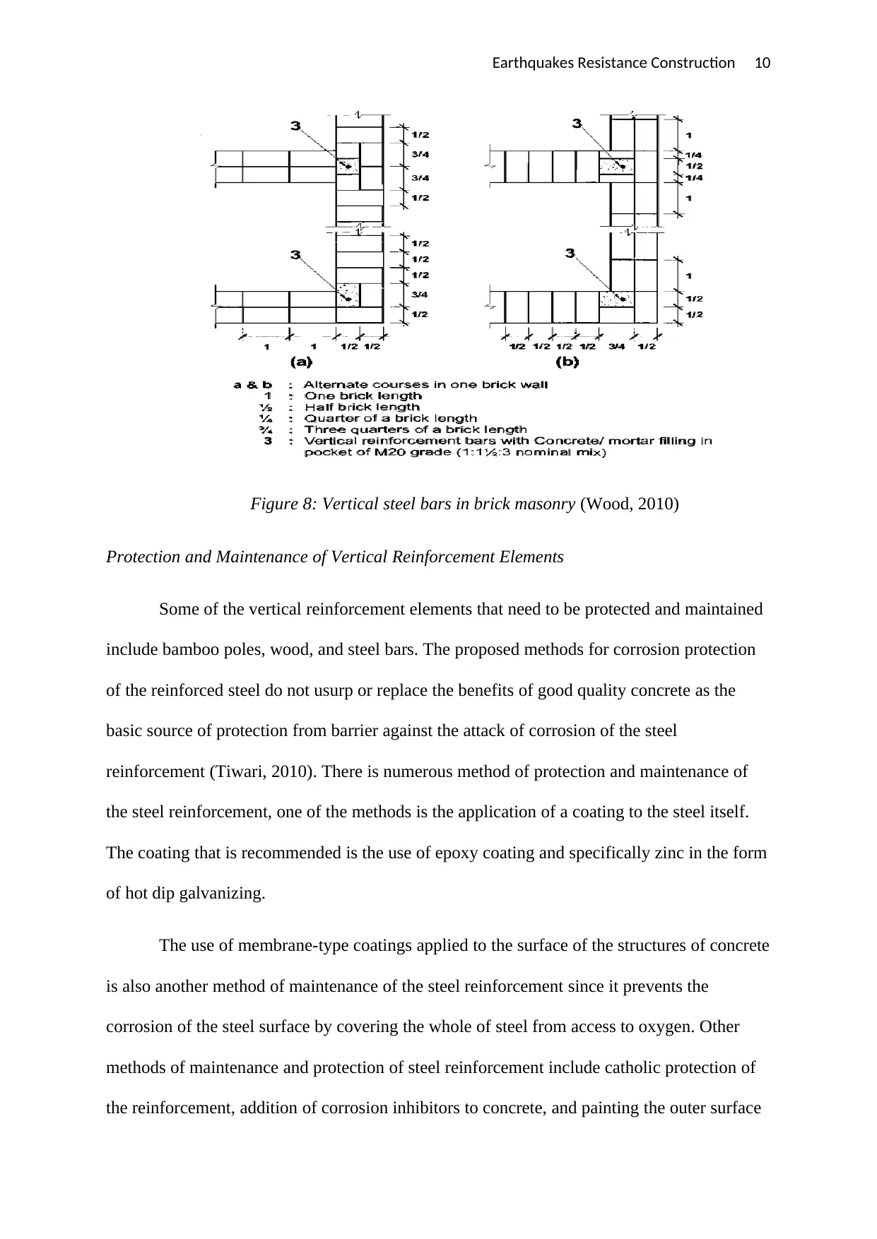
ceiling roof or band slab (Parducci, 2014). The figure below shows the details of vertical steel
bar in a mason made of brick:
the surface of the ground moves in every direction. The damages of the construction are as a
result of the lateral movement which is opposite to the lateral loads being applied (Correia,
2012).
The bars for vertical reinforcement are slid into position from the top and weaved into
horizontal reinforcement and safeguarded into correct location depending on the specs and
plans of the project. The bars for reinforcement have been embedded in brick masonry at the
corners of every room and the section of the openings of doors for earthquake safety zone V.
Windows opening in the dimensions larger than 60 cm will also require bars for
reinforcement (Kuniyoshi, 2015). The bar diameter that is used in the reinforcement of the
vertical sections depends on the number of storeys in the construction as shown in the table
below:
Figure 7: Sizes of vertical steel recommended (Naeim, 2014)
The provision of the vertical bars in the concrete blocks and brickwork needs
exceptional methods which could be learnt easily. These vertical bars have to be initiated
from the concrete of foundation, then pass through all seismic bands where they are attached
to the reinforcement bands by the use of wire for binding and then lastly embedded to the
ceiling roof or band slab (Parducci, 2014). The figure below shows the details of vertical steel
bar in a mason made of brick:
⊘ This is a preview!⊘
Do you want full access?
Subscribe today to unlock all pages.
Trusted by 1+ million students worldwide
Earthquakes Resistance Construction 10
Figure 8: Vertical steel bars in brick masonry (Wood, 2010)
Protection and Maintenance of Vertical Reinforcement Elements
Some of the vertical reinforcement elements that need to be protected and maintained
include bamboo poles, wood, and steel bars. The proposed methods for corrosion protection
of the reinforced steel do not usurp or replace the benefits of good quality concrete as the
basic source of protection from barrier against the attack of corrosion of the steel
reinforcement (Tiwari, 2010). There is numerous method of protection and maintenance of
the steel reinforcement, one of the methods is the application of a coating to the steel itself.
The coating that is recommended is the use of epoxy coating and specifically zinc in the form
of hot dip galvanizing.
The use of membrane-type coatings applied to the surface of the structures of concrete
is also another method of maintenance of the steel reinforcement since it prevents the
corrosion of the steel surface by covering the whole of steel from access to oxygen. Other
methods of maintenance and protection of steel reinforcement include catholic protection of
the reinforcement, addition of corrosion inhibitors to concrete, and painting the outer surface
Paraphrase This Document
Need a fresh take? Get an instant paraphrase of this document with our AI Paraphraser
Earthquakes Resistance Construction 11
of the concrete (Russell, 2013). The application of the coating which is sometimes known as
penetrating pore-liners may be used to minimize the content of moisture of the reinforced bar
and hence suppressing the reaction leading to corrosion.
An already damaged steel reinforcement can be repaired through reactive repair
strategies such as patch repair where the concrete cover is removed to easy access to the
corroded steel and then the corroded parts are cleaned by the use of wire brush or
sandblasting (Paulay, 2011). The other vertical reinforcement elements like bamboo and
wood should also be maintained and protected by carrying out some basic rules such as
avoiding direct contact with soil, not using nails on the bamboo or wood, and handling the
elements with proper care. The elements should be coated with especial bitumen paint or tar
which provides protection from rotting. Nails can make the bamboo poles to split because of
the anatomical structure of the fibres of bamboo which run in the similar longitudinal
direction. Screws are recommended in case a slightly smaller pilot hole is pre-drilled in the
pole (Parducci, 2014).
Plinth Beam and Foundation
Plinth beam is a beam in a structure that is framed delivered above or at ground level
that supports the weight of the wall constructed on top of it. Majority of the beams are
subjected to loads from the slab and also loads from walls. The plinth beams also serve
another purpose like reducing the column lengths hence minimizing their effective thinness
and length. It is also known as level of the ground floor and it is the region where the column
start rising. The plinth beams are used to avoid difficulties in wall construction, connecting
all columns in case foundation depth is high, and avoiding differential settlement.
Earthquakes Resistance Construction 12
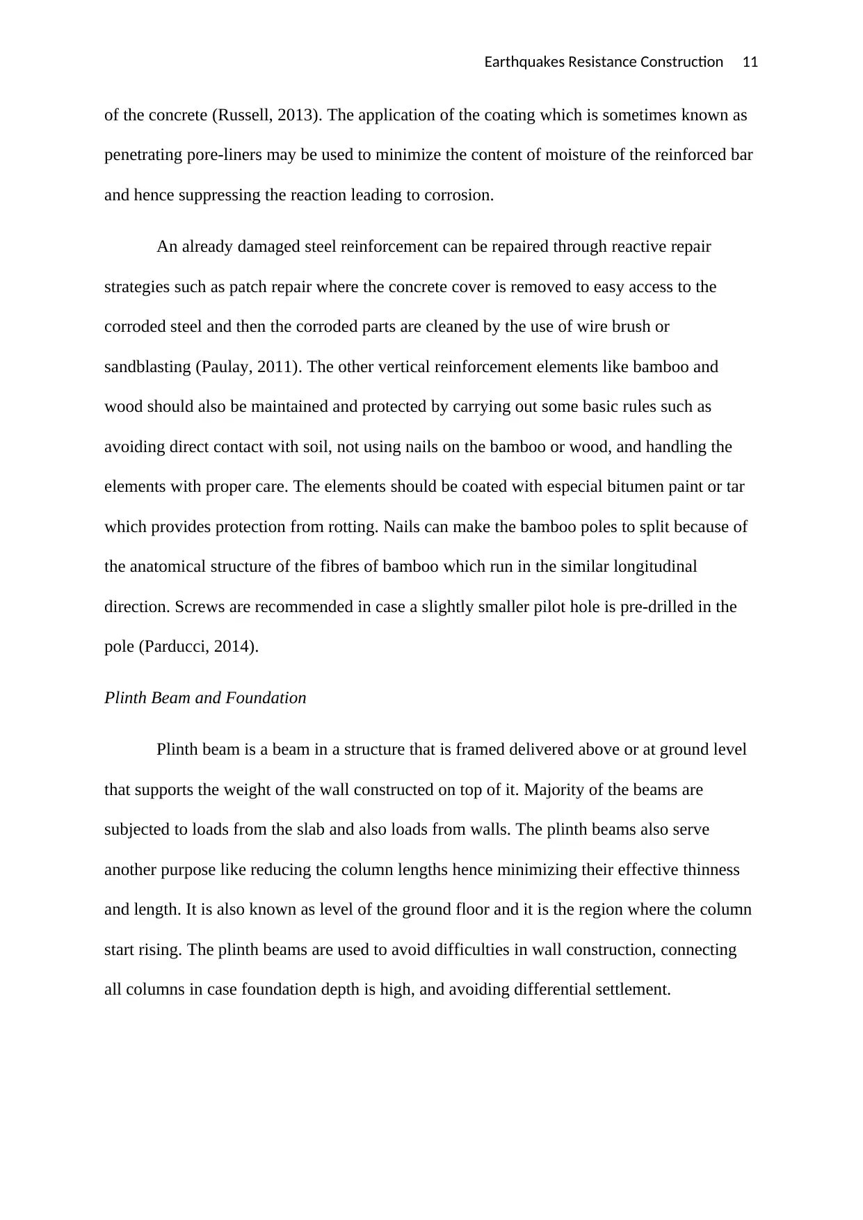
Figure 9: The connection of plinth beam with the strip and pad foundation (Arnold, 2013)
Plinth beams are normally situated where the foundations are little deeper and hence
perform like a tying or bracing element. Plinth beam should be constructed initially as soon
as the foundation is erected. The plinth beam is usually expected to be strong enough for
bearing effectively the superimposing brick walls tying the foundation and the column. The
depth of the plinth is 20 cm while the width being equivalent to the final foundation course
(Parducci, 2014).
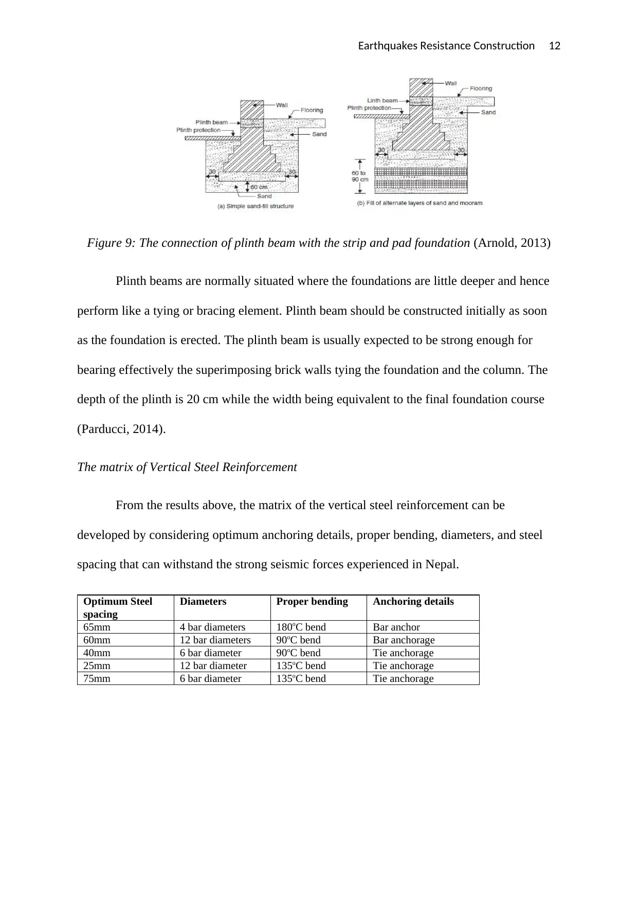
The matrix of Vertical Steel Reinforcement
From the results above, the matrix of the vertical steel reinforcement can be
developed by considering optimum anchoring details, proper bending, diameters, and steel
spacing that can withstand the strong seismic forces experienced in Nepal.
Optimum Steel
spacing
Diameters Proper bending Anchoring details
65mm 4 bar diameters 180oC bend Bar anchor
60mm 12 bar diameters 90oC bend Bar anchorage
40mm 6 bar diameter 90oC bend Tie anchorage
25mm 12 bar diameter 135oC bend Tie anchorage
75mm 6 bar diameter 135oC bend Tie anchorage
Figure 9: The connection of plinth beam with the strip and pad foundation (Arnold, 2013)
Plinth beams are normally situated where the foundations are little deeper and hence
perform like a tying or bracing element. Plinth beam should be constructed initially as soon
as the foundation is erected. The plinth beam is usually expected to be strong enough for
bearing effectively the superimposing brick walls tying the foundation and the column. The
depth of the plinth is 20 cm while the width being equivalent to the final foundation course
(Parducci, 2014).
The matrix of Vertical Steel Reinforcement
From the results above, the matrix of the vertical steel reinforcement can be
developed by considering optimum anchoring details, proper bending, diameters, and steel
spacing that can withstand the strong seismic forces experienced in Nepal.
Optimum Steel
spacing
Diameters Proper bending Anchoring details
65mm 4 bar diameters 180oC bend Bar anchor
60mm 12 bar diameters 90oC bend Bar anchorage
40mm 6 bar diameter 90oC bend Tie anchorage
25mm 12 bar diameter 135oC bend Tie anchorage
75mm 6 bar diameter 135oC bend Tie anchorage
⊘ This is a preview!⊘
Do you want full access?
Subscribe today to unlock all pages.
Trusted by 1+ million students worldwide
1 out of 18
Related Documents


Your All-in-One AI-Powered Toolkit for Academic Success.
+13062052269
info@desklib.com
Available 24*7 on WhatsApp / Email
![[object Object]](/_next/static/media/star-bottom.7253800d.svg)
Unlock your academic potential
Copyright © 2020–2026 A2Z Services. All Rights Reserved. Developed and managed by ZUCOL.