EAT119: Electrical & Electronic Principles - Sensor, Logic & AC Load

Verified

Added on  2023/06/09

|7
|766
|321
Report
AI Summary
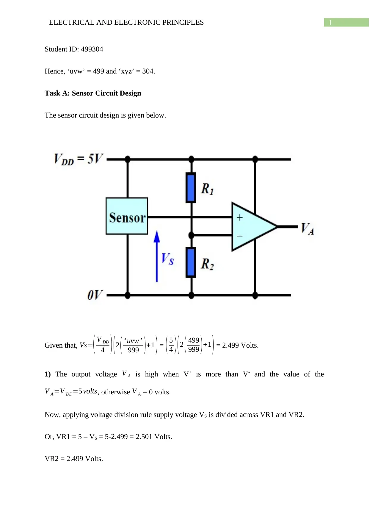
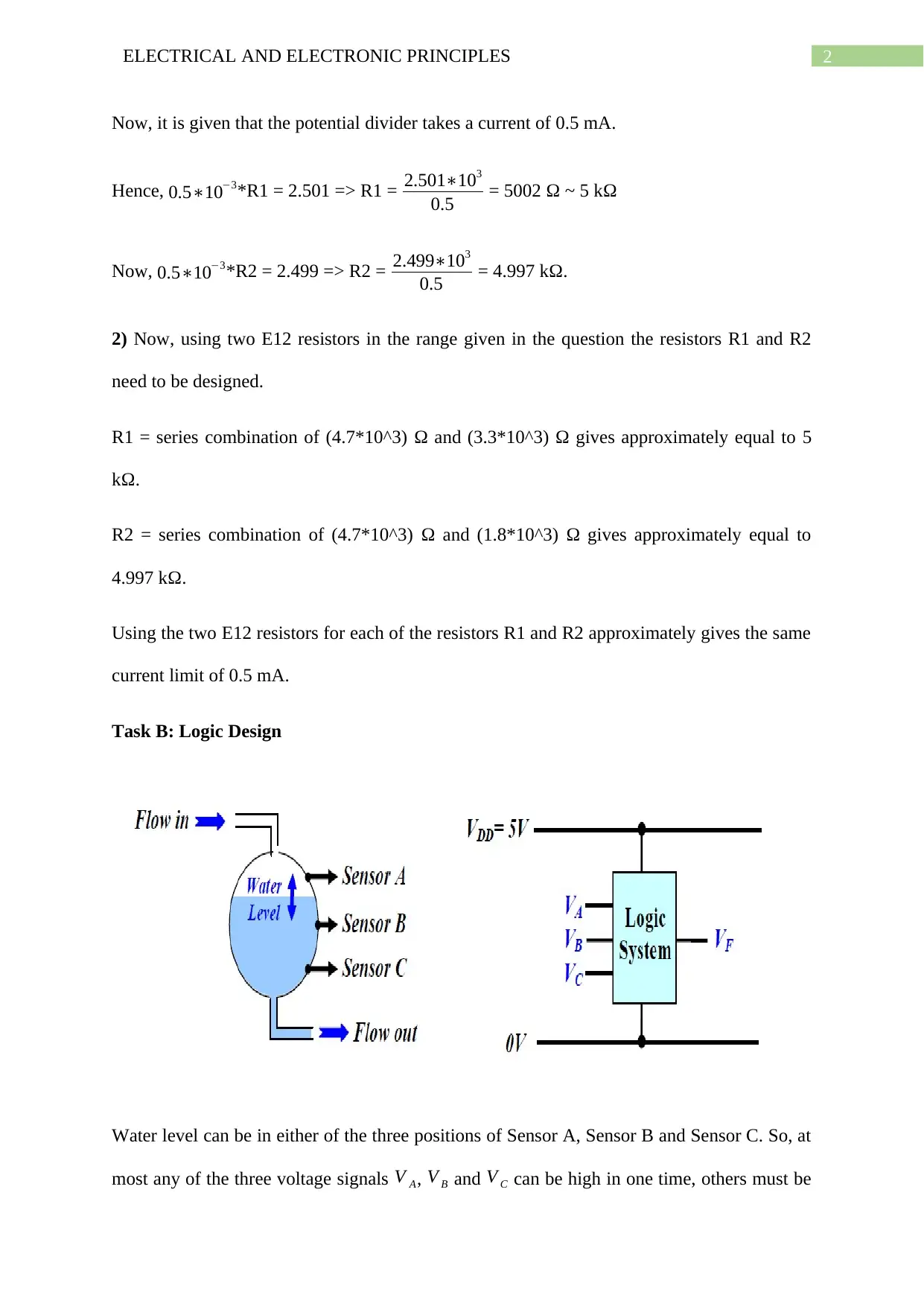
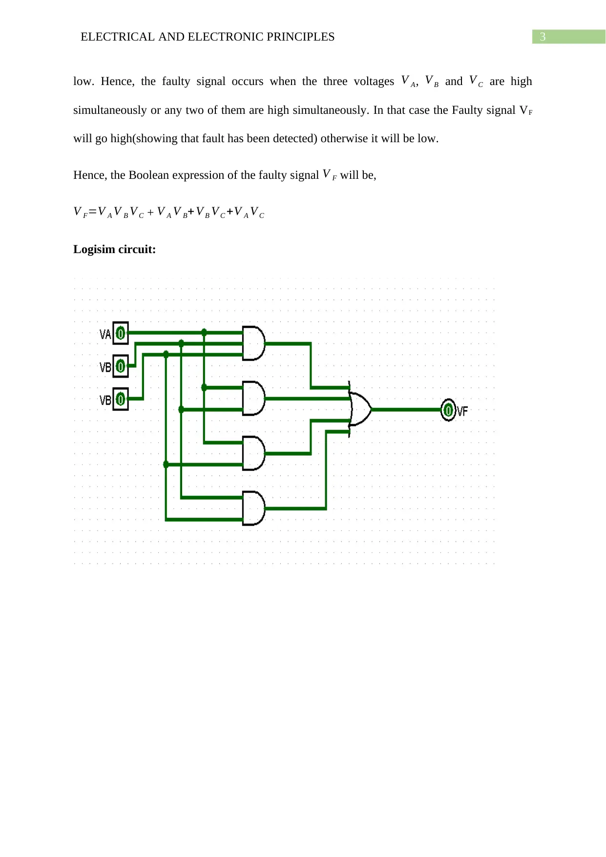
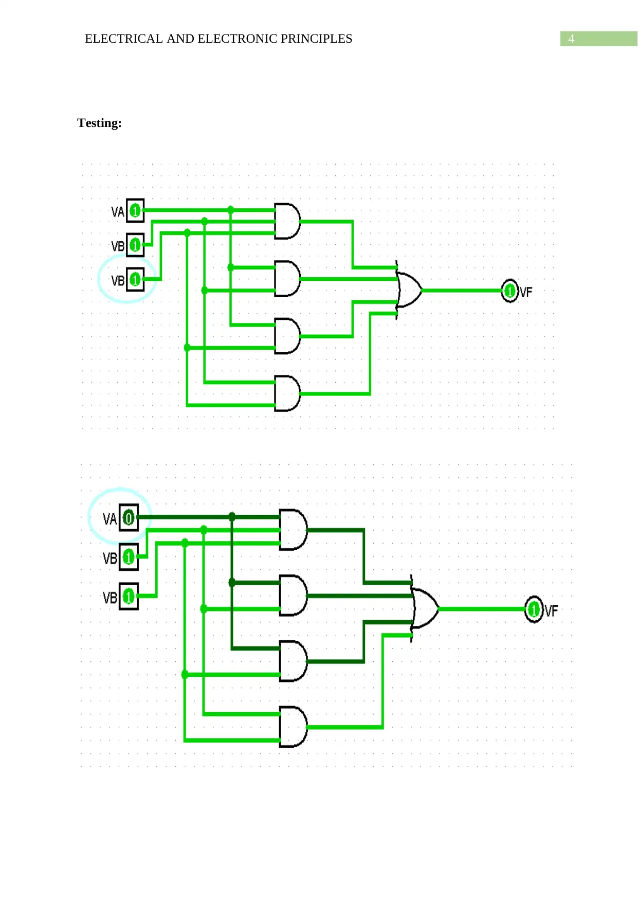
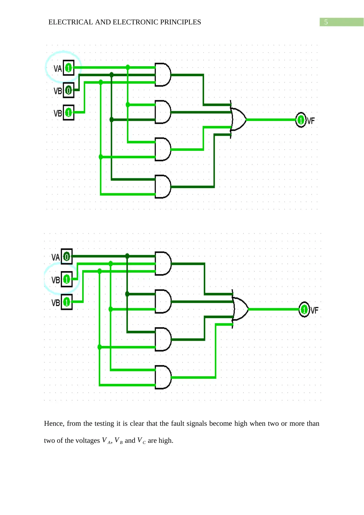
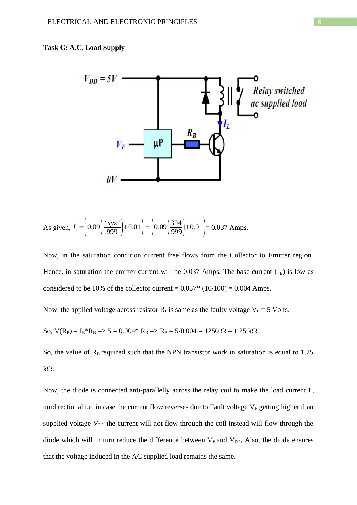
This report provides a detailed analysis and design of electrical and electronic circuits, focusing on three key areas: sensor circuit design, logic design, and AC load supply. The sensor circuit design involves calculating resistor values for a potential divider using given voltage and current parameters, followed by practical implementation using E12 series resistors. The logic design section details the implementation of a fault detection system for a water level monitoring application using logic gates, with a Boolean expression derived and tested using Logisim. Finally, the AC load supply section calculates the required base resistor value for an NPN transistor to operate in saturation, controlling a relay coil connected to an AC load, with a diode included for protection. This report showcases practical application of electrical and electronic principles and is available for review on Desklib, where students can find a wide array of solved assignments and past papers.
Document Page
Running head: ELECTRICAL AND ELECTRONIC PRINCIPLES
EAT119 Electrical and Electronic Principles
Name of the Student
University of Sunderland
Author Note
tabler-icon-diamond-filled.svg

Paraphrase This Document

Need a fresh take? Get an instant paraphrase of this document with our AI Paraphraser
Document Page
1ELECTRICAL AND ELECTRONIC PRINCIPLES
Student ID: 499304
Hence, ‘uvw’ = 499 and ‘xyz’ = 304.
Task A: Sensor Circuit Design
The sensor circuit design is given below.
Given that, Vs=( V DD
4 ) ( 2 ( uvw
999 ) +1 ) = ( 5
4 ) ( 2 ( 499
999 ) +1 ) = 2.499 Volts.
1) The output voltage V A is high when V+ is more than V- and the value of the
V A =V DD=5 volts, otherwise V A = 0 volts.
Now, applying voltage division rule supply voltage VS is divided across VR1 and VR2.
Or, VR1 = 5 – VS = 5-2.499 = 2.501 Volts.
VR2 = 2.499 Volts.
Document Page
2ELECTRICAL AND ELECTRONIC PRINCIPLES
Now, it is given that the potential divider takes a current of 0.5 mA.
Hence, 0.5103*R1 = 2.501 => R1 = 2.501103
0.5 = 5002 Ω ~ 5 kΩ
Now, 0.5103*R2 = 2.499 => R2 = 2.499103
0.5 = 4.997 kΩ.
2) Now, using two E12 resistors in the range given in the question the resistors R1 and R2
need to be designed.
R1 = series combination of (4.7*10^3) Ω and (3.3*10^3) Ω gives approximately equal to 5
kΩ.
R2 = series combination of (4.7*10^3) Ω and (1.8*10^3) Ω gives approximately equal to
4.997 kΩ.
Using the two E12 resistors for each of the resistors R1 and R2 approximately gives the same
current limit of 0.5 mA.
Task B: Logic Design
Water level can be in either of the three positions of Sensor A, Sensor B and Sensor C. So, at
most any of the three voltage signals V A, V B and V C can be high in one time, others must be
Document Page
3ELECTRICAL AND ELECTRONIC PRINCIPLES
low. Hence, the faulty signal occurs when the three voltages V A, V B and V C are high
simultaneously or any two of them are high simultaneously. In that case the Faulty signal VF
will go high(showing that fault has been detected) otherwise it will be low.
Hence, the Boolean expression of the faulty signal V F will be,
V F=V A V B V C + V A V B+V B V C +V A V C
Logisim circuit:
tabler-icon-diamond-filled.svg

Paraphrase This Document

Need a fresh take? Get an instant paraphrase of this document with our AI Paraphraser
Document Page
4ELECTRICAL AND ELECTRONIC PRINCIPLES
Testing:
Document Page
5ELECTRICAL AND ELECTRONIC PRINCIPLES
Hence, from the testing it is clear that the fault signals become high when two or more than
two of the voltages V A, V B and V C are high.
Document Page
6ELECTRICAL AND ELECTRONIC PRINCIPLES
Task C: A.C. Load Supply
As given, I L=(0.09 ( xyz
999 )+0.01 ) = (0.09 ( 304
999 )+0.01 )= 0.037 Amps.
Now, in the saturation condition current free flows from the Collector to Emitter region.
Hence, in saturation the emitter current will be 0.037 Amps. The base current (IB) is low as
considered to be 10% of the collector current = 0.037* (10/100) = 0.004 Amps.
Now, the applied voltage across resistor RB is same as the faulty voltage VF = 5 Volts.
So, V(RB) = IB*RB => 5 = 0.004* RB => RB = 5/0.004 = 1250 Ω = 1.25 kΩ.
So, the value of RB required such that the NPN transistor work in saturation is equal to 1.25
kΩ.
Now, the diode is connected anti-parallelly across the relay coil to make the load current IL
unidirectional i.e. in case the current flow reverses due to Fault voltage VF getting higher than
supplied voltage VDD the current will not flow through the coil instead will flow through the
diode which will in turn reduce the difference between VF and VDD. Also, the diode ensures
that the voltage induced in the AC supplied load remains the same.
chevron_up_icon
1 out of 7
circle_padding
hide_on_mobile
zoom_out_icon
[object Object]