EAT119 - Electrical and Electronic Principles: Sensor & Logic

Verified

Added on  2023/06/09

|6
|737
|256
Homework Assignment
AI Summary
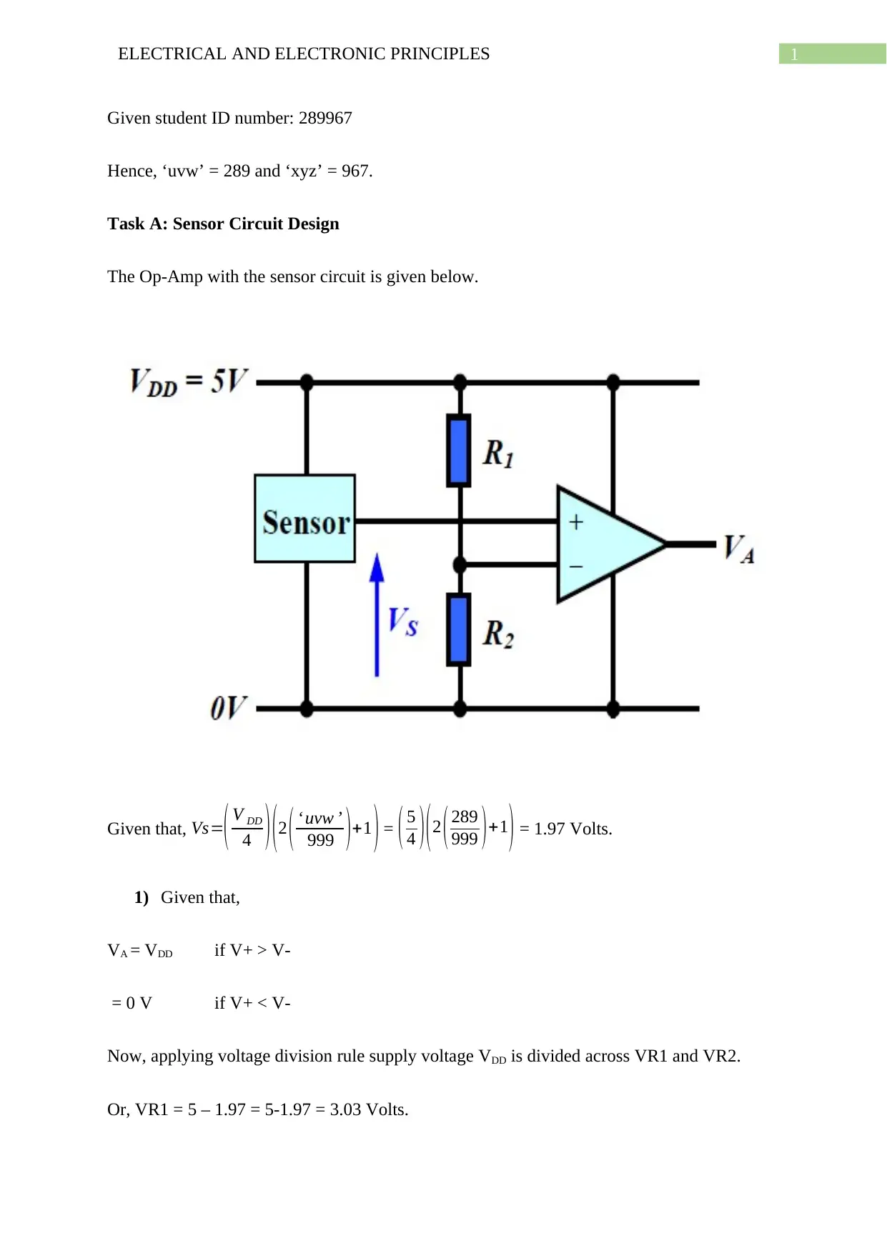
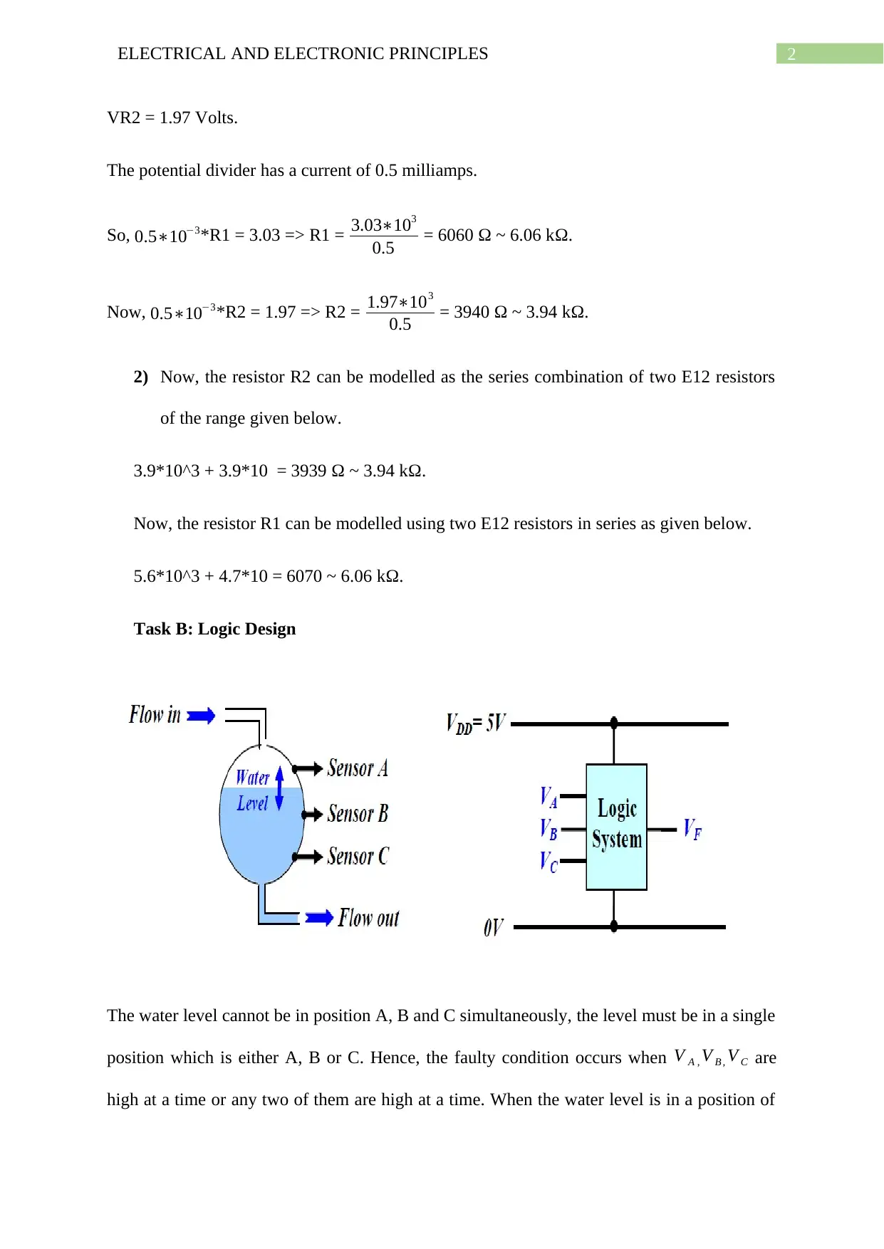
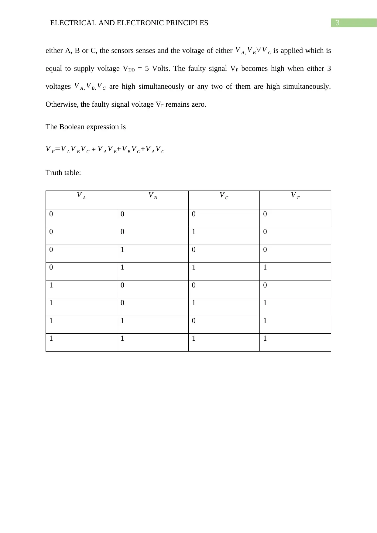
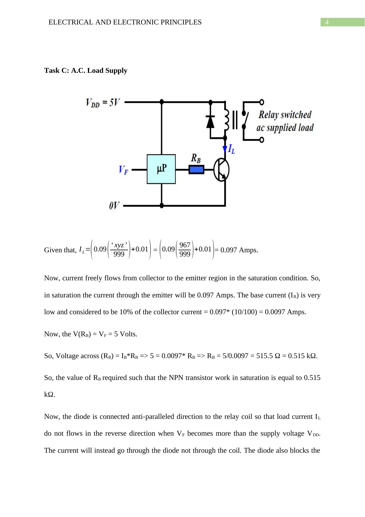
This assignment solution covers electrical and electronic principles, focusing on sensor circuit and logic design. Task A involves designing an Op-Amp sensor circuit, calculating voltage division, and modeling resistors using E12 series components. Task B addresses logic design, specifically addressing a water level monitoring system and creating a Boolean expression and truth table for a faulty condition. Task C focuses on an A.C. load supply, calculating the required base resistor value for an NPN transistor to operate in saturation and explaining the function of a diode connected anti-paralleled to a relay coil. Desklib offers a wide range of solved assignments and study resources for students.
Document Page
Running head: ELECTRICAL AND ELECTRONIC PRINCIPLES
EAT119 Electrical and Electronic Principles
Name of the Student
University of Sunderland
Author Note
tabler-icon-diamond-filled.svg

Paraphrase This Document

Need a fresh take? Get an instant paraphrase of this document with our AI Paraphraser
Document Page
1ELECTRICAL AND ELECTRONIC PRINCIPLES
Given student ID number: 289967
Hence, ‘uvw’ = 289 and ‘xyz’ = 967.
Task A: Sensor Circuit Design
The Op-Amp with the sensor circuit is given below.
Given that, Vs=( V DD
4 ) ( 2 ( uvw
999 ) +1 ) = ( 5
4 ) ( 2 ( 289
999 ) +1
) = 1.97 Volts.
1) Given that,
VA = VDD if V+ > V-
= 0 V if V+ < V-
Now, applying voltage division rule supply voltage VDD is divided across VR1 and VR2.
Or, VR1 = 5 – 1.97 = 5-1.97 = 3.03 Volts.
Document Page
2ELECTRICAL AND ELECTRONIC PRINCIPLES
VR2 = 1.97 Volts.
The potential divider has a current of 0.5 milliamps.
So, 0.5103*R1 = 3.03 => R1 = 3.03103
0.5 = 6060 Ω ~ 6.06 kΩ.
Now, 0.5103*R2 = 1.97 => R2 = 1.97103
0.5 = 3940 Ω ~ 3.94 kΩ.
2) Now, the resistor R2 can be modelled as the series combination of two E12 resistors
of the range given below.
3.9*10^3 + 3.9*10 = 3939 Ω ~ 3.94 kΩ.
Now, the resistor R1 can be modelled using two E12 resistors in series as given below.
5.6*10^3 + 4.7*10 = 6070 ~ 6.06 kΩ.
Task B: Logic Design
The water level cannot be in position A, B and C simultaneously, the level must be in a single
position which is either A, B or C. Hence, the faulty condition occurs when V A , V B , V C are
high at a time or any two of them are high at a time. When the water level is in a position of
Document Page
3ELECTRICAL AND ELECTRONIC PRINCIPLES
either A, B or C, the sensors senses and the voltage of either V A , V BV C is applied which is
equal to supply voltage VDD = 5 Volts. The faulty signal VF becomes high when either 3
voltages V A , V B , V C are high simultaneously or any two of them are high simultaneously.
Otherwise, the faulty signal voltage VF remains zero.
The Boolean expression is
V F=V A V B V C + V A V B+V B V C +V A V C
Truth table:
V A V B V C V F
0 0 0 0
0 0 1 0
0 1 0 0
0 1 1 1
1 0 0 0
1 0 1 1
1 1 0 1
1 1 1 1
tabler-icon-diamond-filled.svg

Paraphrase This Document

Need a fresh take? Get an instant paraphrase of this document with our AI Paraphraser
Document Page
4ELECTRICAL AND ELECTRONIC PRINCIPLES
Task C: A.C. Load Supply
Given that, I L=
(0.09 ( xyz
999 )+0.01 ) = (0.09 ( 967
999 )+0.01 )= 0.097 Amps.
Now, current freely flows from collector to the emitter region in the saturation condition. So,
in saturation the current through the emitter will be 0.097 Amps. The base current (IB) is very
low and considered to be 10% of the collector current = 0.097* (10/100) = 0.0097 Amps.
Now, the V(RB) = VF = 5 Volts.
So, Voltage across (RB) = IB*RB => 5 = 0.0097* RB => RB = 5/0.0097 = 515.5 Ω = 0.515 kΩ.
So, the value of RB required such that the NPN transistor work in saturation is equal to 0.515
kΩ.
Now, the diode is connected anti-paralleled direction to the relay coil so that load current IL
do not flows in the reverse direction when VF becomes more than the supply voltage VDD.
The current will instead go through the diode not through the coil. The diode also blocks the
Document Page
5ELECTRICAL AND ELECTRONIC PRINCIPLES
flow of current from VDD to transistor ensuring that the current flows from AC supplied load
only.
chevron_up_icon
1 out of 6
circle_padding
hide_on_mobile
zoom_out_icon
[object Object]