EE Assignment: Three-Phase Systems, Motors, and Power Measurement
VerifiedAdded on 2023/05/29
|13
|2048
|376
Homework Assignment
AI Summary
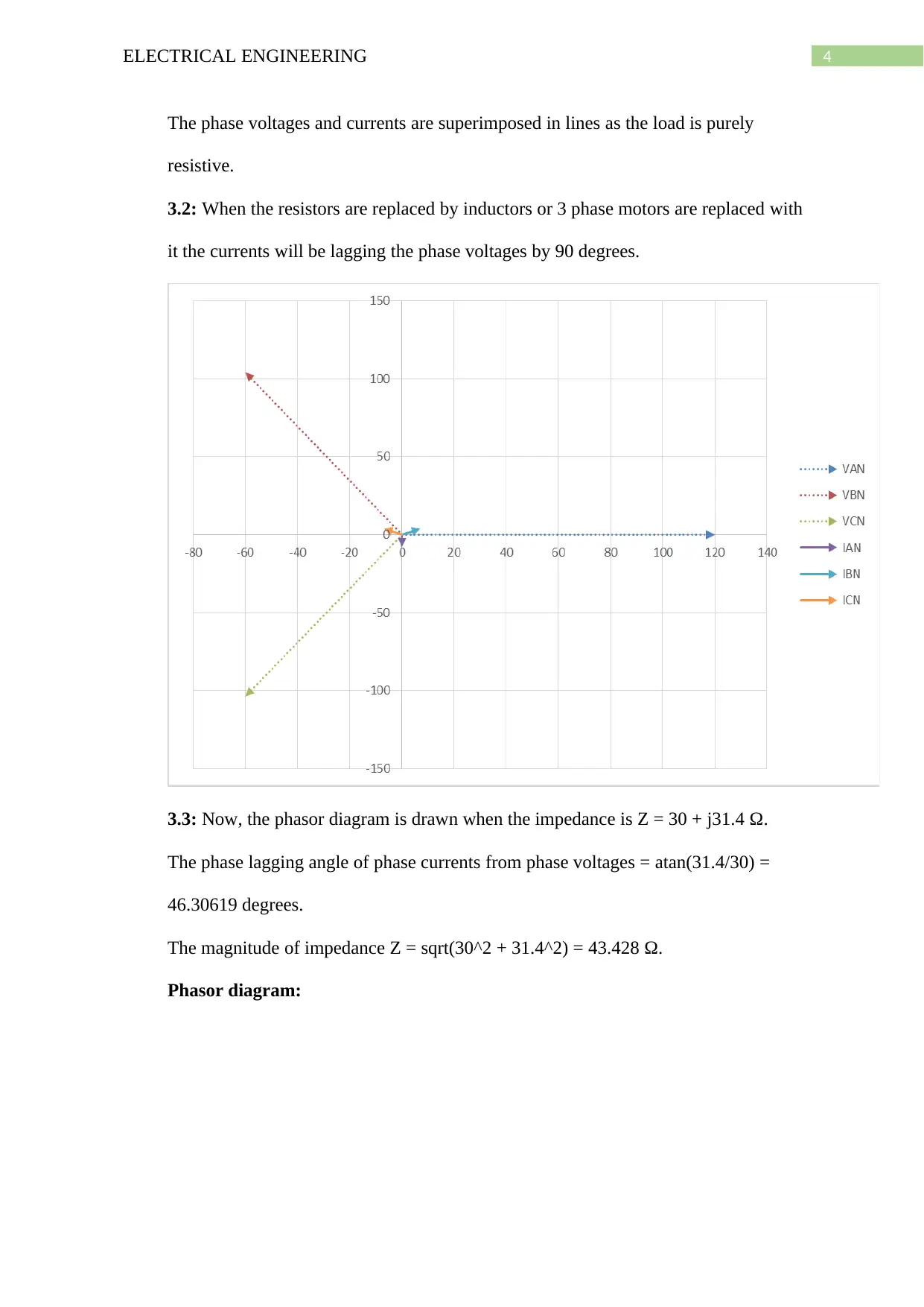
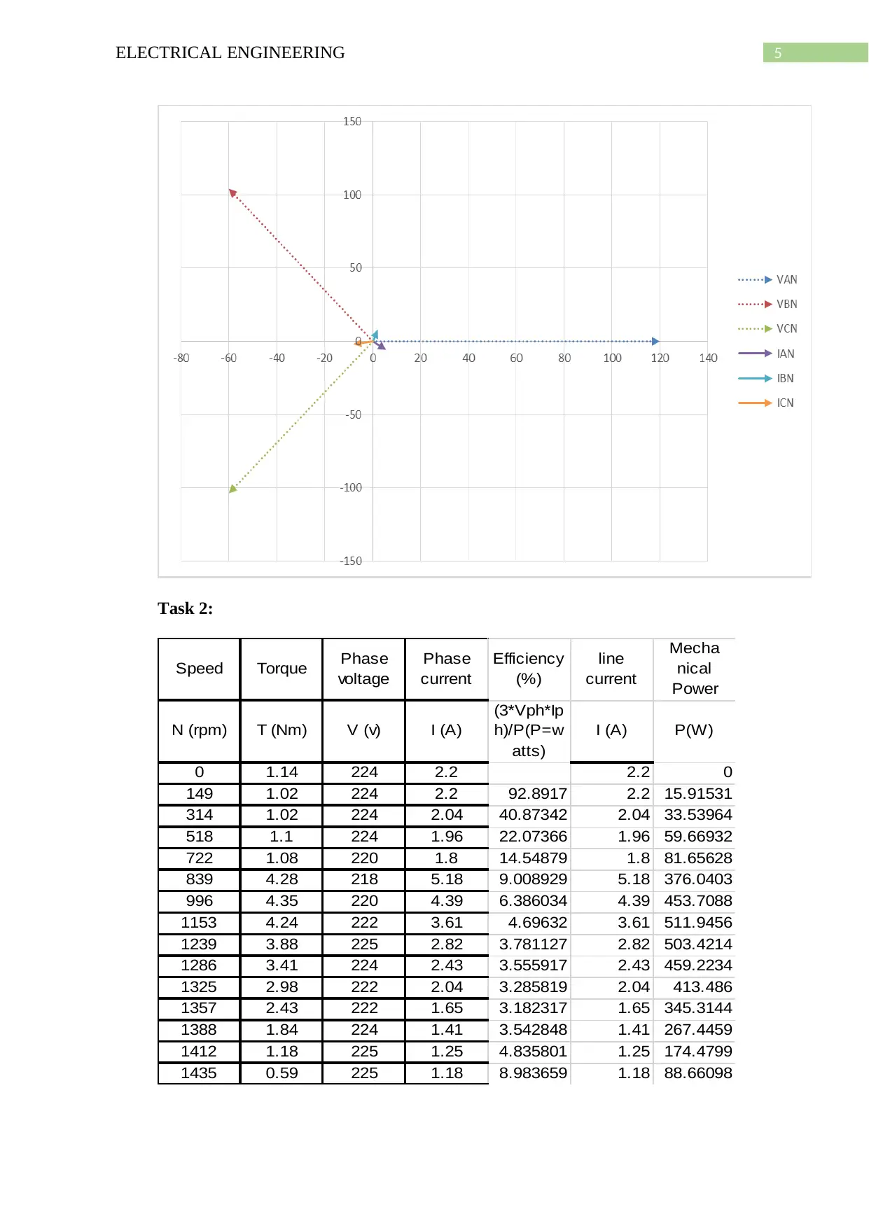
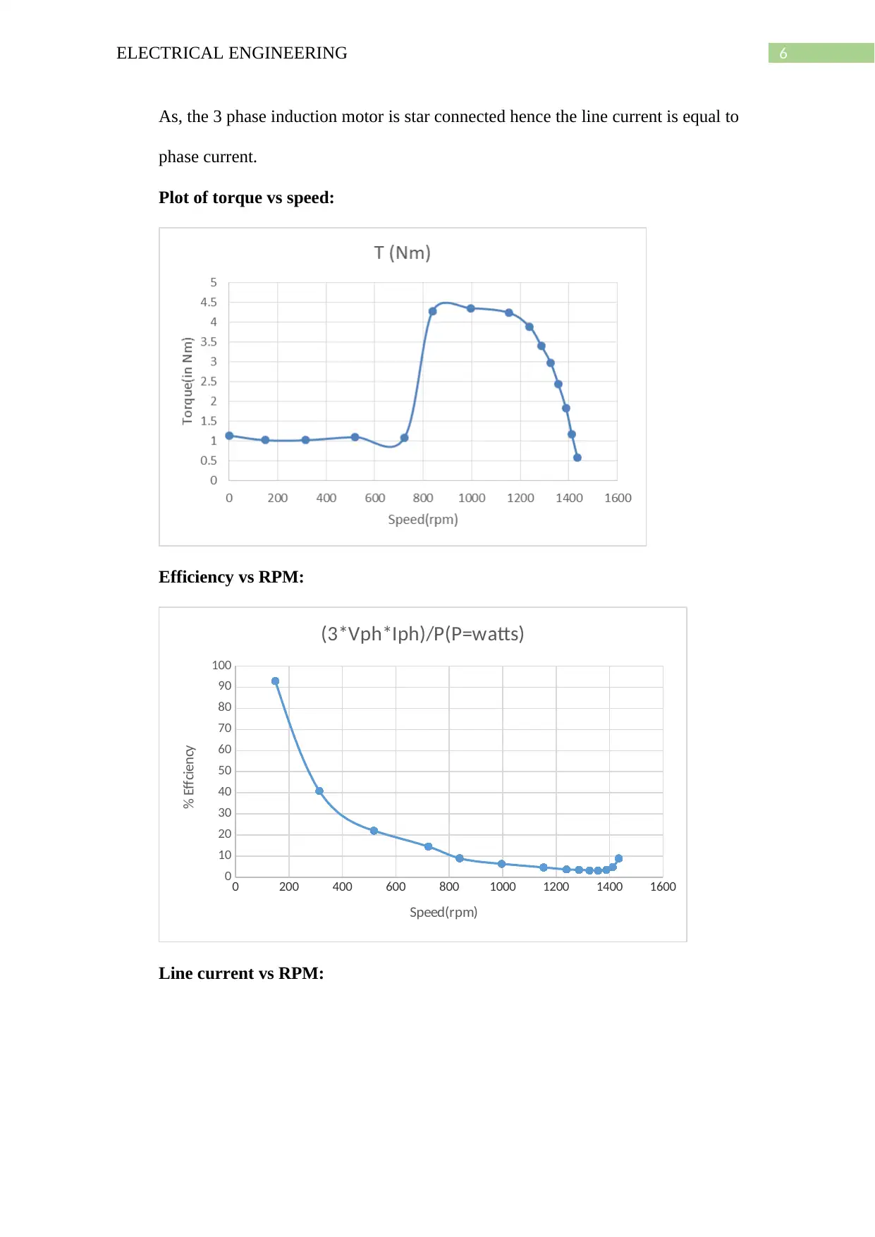
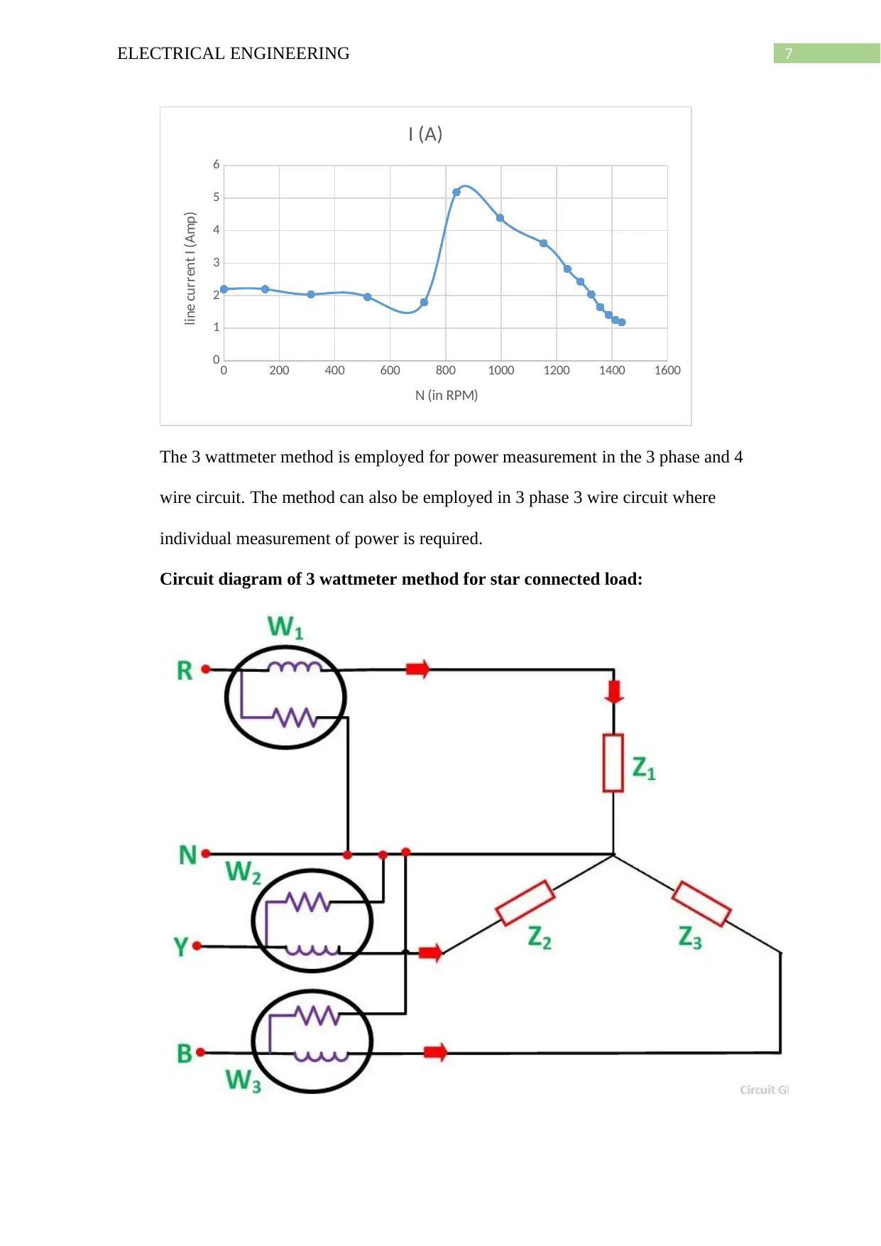
This document provides a comprehensive solution to an electrical engineering assignment focusing on three-phase systems and induction motor characteristics. It includes calculations of line voltage, time intervals between phases, and peak voltage for a star-connected generator. The solution details power dissipation in a delta-delta circuit, phasor diagrams for resistive and inductive loads, and impedance analysis. Furthermore, it examines the speed-torque characteristics of a three-phase induction motor, including efficiency and line current plots, and explains the three-wattmeter method for power measurement. The assignment also addresses the impact of single-phasing on motor operation and discusses the advantages and disadvantages of different three-phase transformer connections. Finally, it outlines the starting and running characteristics of a three-phase cage induction motor, providing a detailed overview of its power-torque curve. Desklib offers a wide range of solved assignments and study resources for students.
Contribute Materials
Your contribution can guide someone’s learning journey. Share your
documents today.

Running head: ELECTRICAL ENGINEERING
ELECTRICAL ENGINEERING
Name of the Student
Name of the University
Author Note
ELECTRICAL ENGINEERING
Name of the Student
Name of the University
Author Note
Secure Best Marks with AI Grader
Need help grading? Try our AI Grader for instant feedback on your assignments.

1ELECTRICAL ENGINEERING
Task 1:
1. The value of X as found from the appendix is 858 KV. Now, this is the phase voltage
of a balanced three phase 50 Hz star connected generator.
Now, the phase voltages are have the magnitude of 858 KV but the phase angles are
0,240 and 120 degrees for phase A,B and C respectively for a star connected system.
Phasor diagram:
Now, the line voltages VAB, VAC and VBC can be calculated by the vector resultant
method. The angle between phase A and C is 120 degree, A and B is 240 degree and
B and C is 120 degree. Hence, the resultant vectors of line voltages VAC, VAB and
VBC will have angles 120/2 = 60, -120/2 = -60 and -120/2 = -60 degrees respectively.
Magnitude of Line voltage VAC = √ VAN2 +VCN 2+2∗VAN∗VCN∗cos 60
= √8582 +8582 +2∗858∗858∗cos 60 = 1486.1 KV.
Similarly, the magnitude of the line voltage VAB
VAB = √VAN2 +VBN 2+ 2∗VAN∗VBN∗cos (−60) = 1486.1 KV.
Also, in the same method the magnitude of line voltage VBC is
VBC = 1486.1 KV.

2ELECTRICAL ENGINEERING
Hence, in general for a balanced three phase star connection
Line voltage = √3∗¿(phase voltage)
Final phasor diagram:
The time interval between the positive peaks of two successive phases like phase A
and phase B is calculated by the following method.
The phase angle difference between two phases is 120 degrees.
Frequency of both phase waves = 500 Hz.
Hence, 500 cycles are completed in 1 sec.
Or, 1 cycle completed in 1/500 secs.
360 degrees completed in 1/500 secs.
120 degrees completed in 120/(500*360) = 0.000667 secs = 0.667 msecs.
Hence, the time intervals between two positive peaks of two successive phases having
a frequency of 500 Hz is 0.667 msecs.
The peak value of line voltage = RMS value * √2 = 1486.1*√2 = 2101.66 KV.

3ELECTRICAL ENGINEERING
2. Now, the delta to delta circuit diagram is shown below.
Now, the phase voltages in each phase is 120 volts and the resistance in phase is 15
kΩ.
Hence, the power dissipated in each phase = V^2/R = 120^2/(15*1000) = 0.96 Watts.
Hence, the total power dissipated = 0.96*3 = 2.88 Watts.
3. Now, the phasor diagrams for different conditions are drawn below.
3.1: Phasor diagram for resistive loads
Secure Best Marks with AI Grader
Need help grading? Try our AI Grader for instant feedback on your assignments.

4ELECTRICAL ENGINEERING
The phase voltages and currents are superimposed in lines as the load is purely
resistive.
3.2: When the resistors are replaced by inductors or 3 phase motors are replaced with
it the currents will be lagging the phase voltages by 90 degrees.
3.3: Now, the phasor diagram is drawn when the impedance is Z = 30 + j31.4 Ω.
The phase lagging angle of phase currents from phase voltages = atan(31.4/30) =
46.30619 degrees.
The magnitude of impedance Z = sqrt(30^2 + 31.4^2) = 43.428 Ω.
Phasor diagram:

5ELECTRICAL ENGINEERING
Task 2:
Speed Torque Phase
voltage
Phase
current
Efficiency
(%)
line
current
Mecha
nical
Power
N (rpm) T (Nm) V (v) I (A)
(3*Vph*Ip
h)/P(P=w
atts)
I (A) P(W)
0 1.14 224 2.2 2.2 0
149 1.02 224 2.2 92.8917 2.2 15.91531
314 1.02 224 2.04 40.87342 2.04 33.53964
518 1.1 224 1.96 22.07366 1.96 59.66932
722 1.08 220 1.8 14.54879 1.8 81.65628
839 4.28 218 5.18 9.008929 5.18 376.0403
996 4.35 220 4.39 6.386034 4.39 453.7088
1153 4.24 222 3.61 4.69632 3.61 511.9456
1239 3.88 225 2.82 3.781127 2.82 503.4214
1286 3.41 224 2.43 3.555917 2.43 459.2234
1325 2.98 222 2.04 3.285819 2.04 413.486
1357 2.43 222 1.65 3.182317 1.65 345.3144
1388 1.84 224 1.41 3.542848 1.41 267.4459
1412 1.18 225 1.25 4.835801 1.25 174.4799
1435 0.59 225 1.18 8.983659 1.18 88.66098

6ELECTRICAL ENGINEERING
As, the 3 phase induction motor is star connected hence the line current is equal to
phase current.
Plot of torque vs speed:
Efficiency vs RPM:
0 200 400 600 800 1000 1200 1400 1600
0
10
20
30
40
50
60
70
80
90
100
(3*Vph*Iph)/P(P=watts)
Speed(rpm)
% Effciency
Line current vs RPM:
As, the 3 phase induction motor is star connected hence the line current is equal to
phase current.
Plot of torque vs speed:
Efficiency vs RPM:
0 200 400 600 800 1000 1200 1400 1600
0
10
20
30
40
50
60
70
80
90
100
(3*Vph*Iph)/P(P=watts)
Speed(rpm)
% Effciency
Line current vs RPM:
Paraphrase This Document
Need a fresh take? Get an instant paraphrase of this document with our AI Paraphraser

7ELECTRICAL ENGINEERING
0 200 400 600 800 1000 1200 1400 1600
0
1
2
3
4
5
6
I (A)
N (in RPM)
line current I (Amp)
The 3 wattmeter method is employed for power measurement in the 3 phase and 4
wire circuit. The method can also be employed in 3 phase 3 wire circuit where
individual measurement of power is required.
Circuit diagram of 3 wattmeter method for star connected load:

8ELECTRICAL ENGINEERING
From the above diagram it can be seen that the pressure coil of the three wattmeters
are connected to the neutral point which is the common terminal of three impedances.
Hence, the total power consumed is
P = W1 + W2 + W3
Where, W1 = V1*I1, W2 = V2*I2 and W3 = V3*I3
Task 3:
When one of the 3 phase windings of a 3 phase motor fails then the motor will
continue or stop running based on the loading condition. If the motor is lightly loaded
then the motor will continue to run for some amount of time at reduced speed but if
the motor is heavily loaded then the motor will stop running. This condition known as
single phase condition of three phase motors. Now, these are effects when one of the
three phases fails or disconnected.
i) The speed of the motor is reduced.
ii) Due to the supply gets misbalanced the motor runs with uneven torque and
hence a humming noise is produced.
iii) As one of the phase is disconnected but the supply voltage remains the same
the current in the remaining two phases will increase and thus damages
windings in the remaining phases as they are not usually supposed to meet the
increased current. This will ultimately damage the insulation between phases
and motor will finally stop.
Now, the failure of one of the phase of the motor can be due to several reasons.
i) Mechanical disturbance while motor is running may loosen the windings and
one of the windings may be disconnected.
ii) If the voltage supply to the motor abruptly changes then the current will also
change abruptly(if inductances in the windings is low) then the power loss in

9ELECTRICAL ENGINEERING
the windings will increase and this damages the coils which will eventually
disconnect one or more windings from the system
iii) Short circuits may occur between the phases through induction if motor MVA
rating is high and gapping between phases is low. This results in high current
increase and this may burn out the motor.
Task 4:
The step down transformer is a transformer in which the primary side voltage is
stepped down to the secondary side. A transformer can be single phase or three phase.
In case of single phase the input and output voltage has two wires however in case of
three phase 3 input and 3 output lines with or without neutral line is there. A
transformer can’t be made as a phase changing device thus either 3 phase or single
phase transformer is produced. A three phase transformer can be made using either by
the combination of three single phase transformers or by using a balanced three phase
transformer bank or with a pre-assembled balanced three phase supply that consists of
the pairs of single phase windings merged by one laminated core. Hence, the primary
and the secondary windings of the three phase transformer can either be delta or star
connected. Hence, the four combinations of primary and secondary windings are
delta-delta, delta-star, star-delta and star-star. In star connections multiple voltages
can be used while in delta connection the voltage level can be increased significantly.
Also, there exist another type of connection which is known as ‘interconnected star’
or ‘zig-zag’ connection. In case of star connected 3 phase transformer voltage can be
reduced and hence, the required number of turns is reduced and coil lengths are
increased which makes it easier for insulating than the delta connected transformers.
However, in delta connected transformers each of the delta connected transformer can
work independently such as if one gets faulty then the other delta connected
Secure Best Marks with AI Grader
Need help grading? Try our AI Grader for instant feedback on your assignments.

10ELECTRICAL ENGINEERING
transformers can convert 3 phase power at a lower level than the actual. In case of the
delta connection the line voltages and phase voltages are equal but the line current is
√3 times of phase current. The disadvantage of the delta connected 3 phase
transformers is that in this connection each of the transformer needs to be wounded
for the full line voltage and 1/ √3 times of line current. This increases the number of
turns in the windings and hence larger and more expensive coils are needed. Also,
another disadvantage of the delta connected transformers is that there is no neutral
connection. However, in star connection three transformers are needed and if one of
the transformer gets faulty then the whole group may be shut down. The advantage of
star connection is that in this case a neutral wire is there which helps to get rid of extra
currents in the circuit when voltage spikes occur and also the star connection is more
economical for reduced coil size in transformer.
In case of 3 phase step down transformer the voltage in the primary side is stepped up
in the secondary side. This is achieved by increasing the number of coil turns in the
secondary size than the primary side. The step up transformers are very useful for
long distribution of power as in many sites or industries higher voltage requirement is
necessary. But, the current from primary to secondary side is reduced to maintain the
conservation of power.
Task 5:
The starting and running characteristics of 3 phase caged induction motor are
i) The starting torque of the 3 phase induction motor is very low and hence it
can’t start with heavy loads.
ii) The torque increases with the speed and hence it is best fitted for pumps, fans
and compressors as those require higher torques at high speed.

11ELECTRICAL ENGINEERING
iii) The torque of 3 phase induction motor is proportional to square of voltage and
hence when voltage is halved the torque becomes one quarter.
iv) With the increase of the resistance in the circuit the torque of the motor also
increases.
v) At the time of starting the induction motor draws more current due to the
deficit of back emf voltage.
vi) At the time of running when load is maintained at constant level motor reaches
steady state. This steady state characteristics can be obtained by using the
blocked rotor and no load test.
Now, the different stages of the power-torque curve of 3 phase induction motor are
shown in the following figure.

12ELECTRICAL ENGINEERING
1 out of 13

Your All-in-One AI-Powered Toolkit for Academic Success.
+13062052269
info@desklib.com
Available 24*7 on WhatsApp / Email
Unlock your academic potential
© 2024 | Zucol Services PVT LTD | All rights reserved.