Electrical Engineering Project: Transmission, Synchronizati, Surges
VerifiedAdded on 2021/05/31
|18
|2848
|102
Project
AI Summary
This electrical engineering project delves into several critical aspects of power systems. Task 2 focuses on calculating total capacitance and inductance, impedance, voltage, current, and transmission and reflection operators in a cable, as well as surge velocity, and how it relates to transmission wave properties. Task 3 explores surge initiation through switching loads and lightning strikes, detailing the damage caused by overvoltage and the mechanisms behind surges. It also discusses methods for controlling surges, including earthing screens, lightning arresters, and overhead earth wires. Task 4 examines synchronization, explaining the use of lamps and electrical test meters, including the three dark lamps method and synchroscope, highlighting their application in matching the frequency, voltage, and phase sequence of alternators. Task 5 concludes by discussing methods for controlling voltage, frequency, and power factor, primarily through the use of Automatic Voltage Regulators (AVR) and other techniques such as shunt condensers and booster transformers. The project provides a comprehensive overview of these essential concepts in electrical engineering.

Name of the Student
Name of the Professor
City/State
Day/Month/Year
Task 2
Name of the Professor
City/State
Day/Month/Year
Task 2
Paraphrase This Document
Need a fresh take? Get an instant paraphrase of this document with our AI Paraphraser
a)
Total capacitance is given by the equation given below
1/CT = 1/C1+1/C2
1/CT = 1/0.02+1/0.48
CT= 0.0192 μF
Total inductance
LT= L1+L2
LT = 2.1+0.75
LT= 2.85 mH
Xc= 1/ 2 πFc
Xc= 1/ (2*3.142*50*2.85*10-6)
Xc=1.657MΩ
XL= 2πFc
XL= 2*3.142*50*2.85*10-3
0.89547Ω
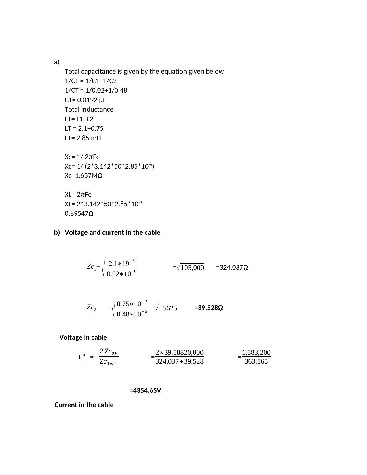
b) Voltage and current in the cable
Zc1= √ 2.1∗19−3
0.02∗10−6 =√105,000 =324.037ῼ
Zc2 =
√ 0.75∗10−3
0.48∗10−6 =√15625 =39.528ῼ
Voltage in cable
F" = 2 Zc2 E
Zc1+Zc2
= 2∗39.58820,000
324.037+39.528 = 1,583,200
363.565
=4354.65V
Current in the cable
Total capacitance is given by the equation given below
1/CT = 1/C1+1/C2
1/CT = 1/0.02+1/0.48
CT= 0.0192 μF
Total inductance
LT= L1+L2
LT = 2.1+0.75
LT= 2.85 mH
Xc= 1/ 2 πFc
Xc= 1/ (2*3.142*50*2.85*10-6)
Xc=1.657MΩ
XL= 2πFc
XL= 2*3.142*50*2.85*10-3
0.89547Ω
b) Voltage and current in the cable
Zc1= √ 2.1∗19−3
0.02∗10−6 =√105,000 =324.037ῼ
Zc2 =
√ 0.75∗10−3
0.48∗10−6 =√15625 =39.528ῼ
Voltage in cable
F" = 2 Zc2 E
Zc1+Zc2
= 2∗39.58820,000
324.037+39.528 = 1,583,200
363.565
=4354.65V
Current in the cable
1 = 4354.65
39.528 =110.166A
c) Transmission and reflection operators
From line A to cable
Transmission operator T = 2 Zc2
( Zc1 +Zc2
)
= 2∗39.528
(324.037+39.528)
From line A to cable = 79.056
363.565 = 0.21745
From cable to lines A and B
Reflection operator = T = ( Zc2− Zc2
)
( Zc1+ Zc2
) = (324.037−39.528)
(324.037+39.528)
= 284.509
363.569
=0.782553
From line A to cable
Reflection operator T=(Zc2− Zc1
)
( Zc1+ Zc2
) = (39.528−324.037)
(324.037+ 39.528)
=−284.509
363.569
=-0.782553
d) Transmission and reflection operators for the cable going into the line
Transmission= 2 Zc 1
¿ ¿
⊘ This is a preview!⊘
Do you want full access?
Subscribe today to unlock all pages.
Trusted by 1+ million students worldwide
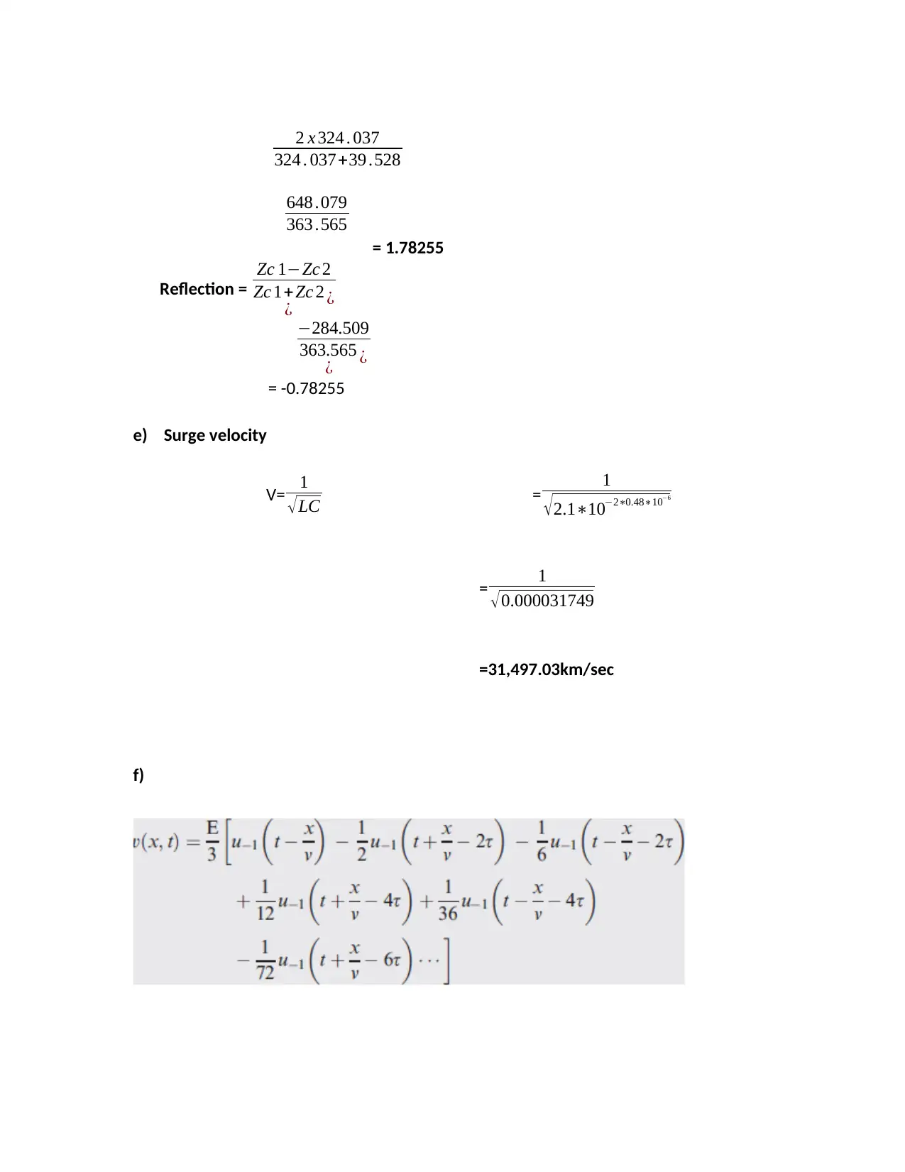
2 x 324 . 037
324 . 037+39 .528
648 .079
363 .565
= 1.78255
Reflection =
Zc 1−Zc 2
Zc 1+Zc 2
¿ ¿
−284.509
363.565
¿ ¿
= -0.78255
e) Surge velocity
V= 1
√LC = 1
√2.1∗10−2∗0.48∗10−6
= 1
√0.000031749
=31,497.03km/sec
f)
324 . 037+39 .528
648 .079
363 .565
= 1.78255
Reflection =
Zc 1−Zc 2
Zc 1+Zc 2
¿ ¿
−284.509
363.565
¿ ¿
= -0.78255
e) Surge velocity
V= 1
√LC = 1
√2.1∗10−2∗0.48∗10−6
= 1
√0.000031749
=31,497.03km/sec
f)
Paraphrase This Document
Need a fresh take? Get an instant paraphrase of this document with our AI Paraphraser
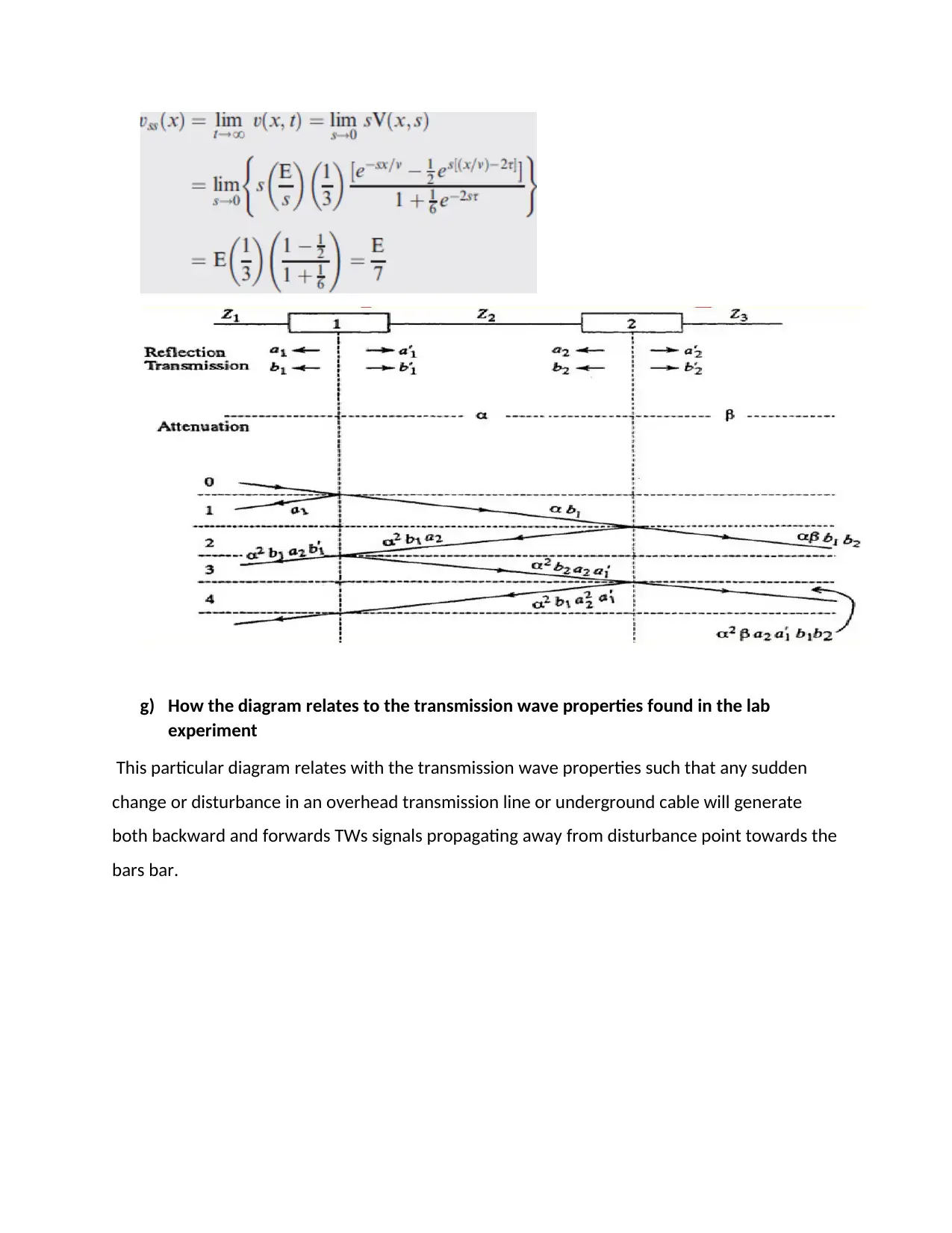
g) How the diagram relates to the transmission wave properties found in the lab
experiment
This particular diagram relates with the transmission wave properties such that any sudden
change or disturbance in an overhead transmission line or underground cable will generate
both backward and forwards TWs signals propagating away from disturbance point towards the
bars bar.
experiment
This particular diagram relates with the transmission wave properties such that any sudden
change or disturbance in an overhead transmission line or underground cable will generate
both backward and forwards TWs signals propagating away from disturbance point towards the
bars bar.
Task 3
Surge initiation on the transmission line by switching loads and lightning strikes
An electrical device is designed to handle a specific voltage but they damage in case the devices
are subjected to a higher voltage than what they are designed for. The longer the period over
the higher voltage is experienced, the greater the damage. The most common damage is
triggered by the extreme voltage involving the quick heating and successive cooling of electrical
wiring. In case the wiring in an office or home experiences brief jolts of high electrical voltage
and the causes of the power surges may be as a result of overloading the circuits, damaged or
exposed wiring which causes power surge since the electricity flowing through them is not
being handled or directed the way it normally should. High power electrical devices such
refrigerator, elevators, and conditioning in case they are powered on, they tend to draw an
unusually large amount of electricity thus the extra power causes overpowering of the circuit
and other appliances and other electronics in its path (Lu, 2015, p. 156).
How surge is caused in transmission lines by
Switching loads
⊘ This is a preview!⊘
Do you want full access?
Subscribe today to unlock all pages.
Trusted by 1+ million students worldwide
When the switching on of no-load transmission line is suddenly done, then the voltage of the
line becomes twice compared to the normal system’s voltage. This particular voltage is
transient in nature thus in case of interruption or switching off of a loaded line causes the
voltage across the lines to become high enough thus chopping in the system majorly during
opening operations of the air blast circuit breaker which causes overvoltage in the system.
The alive conductor is earthed suddenly during insulation failure and this is also capable of
causing overvoltage in the system and in case there is distortion in the emf wave produced by
the alternator, it will result to the occurrence of the resonance (Kyamakya, 2017, p. 678).
lightning strikes
Lightning originating from a charged cloud is an electric charge in form of flash or spark. The
bottom area of the cloud is negatively charged and possesses a temperature of -50 degrees
Celsius while the main positive charge center is situated numerous kilometers higher up,
therefore, the energy dissipated in a lightning flash ranges from 1000 to 10000MJ. The problem
on transmission line caused by the lightning strikes is experienced when the negatively charged
charges from the bottom of the cloud induce charges possessing conflicting polarity on the
transmission line. These are held in place of the in the capacitances between the cloud and the
line, the line, and earth until discharging of the clouds occurs as a result of lightning stroke
(Mazzanti, 2013, p. 322).
Paraphrase This Document
Need a fresh take? Get an instant paraphrase of this document with our AI Paraphraser
Methods of controlling disruption of surges
The main methods used in controlling surges include;
a) Earthing screen
This method is mostly used compared to the electrical substation. In this method, a set of GI
wire is mounted over the sub-station and they are used for earthing and they are grounded
properly through different sub-stations structures. The grounding of GI wire offers a little
resistance route to the ground for lightning strokes. This approach of high voltage protection is
economic and simple but it has a disadvantage since the system cannot be protected from
traveling wave which may reach the sub-station through dissimilar feeders (Rachid, 2008, p.
56).
b) Lightning Arrester
This type of device provides very low impedance path to the ground for traveling waves
possessing high voltage and also behaves like a non-linear electrical resistance. As the voltage
increases, the resistance also decreases and vice-versa.
c) Overhead Earth Wire
The overhead earth wire is placed over an electrical sub-station whereby it is placed over the
transmission network. The overhead earth wire or ground wires assist in diverting all the
lightning strokes to the ground instead of permitting them to strike directly on the transmission
conductors (Smeets, 2014, p. 79).
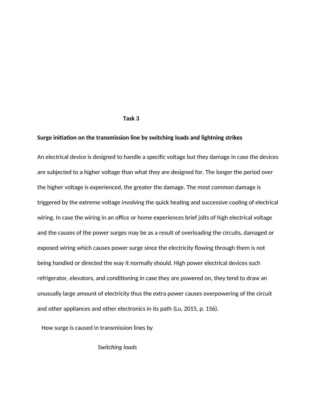
The surges on the transmission line can be caused by three possible discharge path which
includes
a) The primary route is from the lightning stroke to the earth whereby the capacitance
between the earth and the leader is promptly discharged while the phase conductor is
discharged ultimately by traveling wave action resulting when the capacitance from the
leader moves to the earth wire. This causes induced voltage caused by the lightning
stroke to nearby ground (Jensen, 2014, p. 111).
b) The following discharge route is amid the earth conductor and the lightning head where
the capacitance is discharged between the two. The resulting traveling wave comes
down the tower, acting through its effective impedance and raises the potential of the
lower top to a point where the differences in voltage are enough to cause the flashover
to the conductor (Humpage, 2011, p. 561).
possessing high voltage and also behaves like a non-linear electrical resistance. As the voltage
increases, the resistance also decreases and vice-versa.
c) Overhead Earth Wire
The overhead earth wire is placed over an electrical sub-station whereby it is placed over the
transmission network. The overhead earth wire or ground wires assist in diverting all the
lightning strokes to the ground instead of permitting them to strike directly on the transmission
conductors (Smeets, 2014, p. 79).
The surges on the transmission line can be caused by three possible discharge path which
includes
a) The primary route is from the lightning stroke to the earth whereby the capacitance
between the earth and the leader is promptly discharged while the phase conductor is
discharged ultimately by traveling wave action resulting when the capacitance from the
leader moves to the earth wire. This causes induced voltage caused by the lightning
stroke to nearby ground (Jensen, 2014, p. 111).
b) The following discharge route is amid the earth conductor and the lightning head where
the capacitance is discharged between the two. The resulting traveling wave comes
down the tower, acting through its effective impedance and raises the potential of the
lower top to a point where the differences in voltage are enough to cause the flashover
to the conductor (Humpage, 2011, p. 561).
⊘ This is a preview!⊘
Do you want full access?
Subscribe today to unlock all pages.
Trusted by 1+ million students worldwide
c) The third discharge is between the phase conductor and the lead core where the
capacitance is charged between these two and the main discharge current is injected
into the phase conductor, so developing a surge impedance voltage across the insulator
string (Rajput, 2008, p. 98).
The overvoltage can be produced by lightning when it smashes the line conductors (direct
stroke) or a point in the locality of the supply network (indirect stroke). The impressing of the
overvoltage can be done by atmospheric discharge and the magnitudes of lightning surges
appearing on the transmission lines which are mostly affected by the designing of the line.
Task 4
Explaining the use of lamps and electrical test meters during synchronization
Synchronization is simply the procedure of matching elements for example frequency, phase
sequence, voltage, waveform alternator, phase sequence and extra sources with running or
efficient power system. The power cannot be delivered by the generator unless the frequency,
voltage and other parameters and the networks are matching.
The actual synchronization process involves the following procedures;
Considering that the bus bar is supplied with power at rated frequency and voltage.
Secondly, the alternator -2 and alternator-1 to be connected parallel to each other. The
frequency is increased as a result of increasing the alternator speed and this also causes
an adjustment in speed till it matches with the frequency of the bus bar.
Paraphrase This Document
Need a fresh take? Get an instant paraphrase of this document with our AI Paraphraser
The generation of three voltages by the alternator-2must be in phase with the specific
voltage of the bus bar and this can be attained by upholding the same frequency and
phase sequence of alternator-2 with the alternator-1 bus bar (Hossain, 2014, p. 12).
One of the methods used for synchronizing the machine include; Three Dark Lamps Method
and Synchroscope.
Three Dark Lamps
The connection of the three lamps takes place across the switches of the alternator-2. The
alternator is synchronizing by driving the alternator prime mover at a velocity adjacent to the
synchronous speed decided by the frequency of the bus bar and the number of poles of the
alternator. On and off rate of the lamp is decided based on the difference in frequency between
the bus bar voltage and alternator-2 voltage (Glover, 2016, p. 333).
When all the parameters are put in order then the lamp becomes darker and then the
synchronizing switch can be closed to synchronize alternator-2 with alternator-1. The major
demerit of this approach is that the flickering rate only shows the difference between the bus
bar and the alternator-2. Lamps and bright technique is not a correct method since it needs a
correct sense of judgment, therefore, personal judgment should be avoided (Diesendorf, 2015,
p. 321).
In synchronization of three-phase alternators, there is a connection of three lamps so as to
assist in indicating whether the incoming machine is running fast or low. The lamps would glow
up or dark out in case of symmetrical connections so long as the phase sequence for base bar
and the incoming machine is similar. In synchronization of alternators, there are conditions that
should be met which include;
The voltage of the bus bar of the entering machine must be similar to the terminal
voltage.
The frequency of the bus bar must be similar to that of the incoming machine and this
indicates that there must be a proper adjustment of speed.
Phase sequence for the two voltages must be similar with respect to the external load.
Synchronization by Synchroscope
This is an accurate device comprising a rotary pointer which assists in showing the accurate
moment of closing the synchronizing switch. In a situation where the rotation of the pointer
takes place in an anticlockwise route, therefore, it shows that the entering machine is running
low whereas an indication that the mechanism is operating quicker is when the pointer is
rotating in the clockwise direction. The turning of the pointer is relational to the difference in
the two frequencies (Humpage, 2011, p. 75). The rotation of the pointer should take place at a
very low speed in the marked direction in the figure
⊘ This is a preview!⊘
Do you want full access?
Subscribe today to unlock all pages.
Trusted by 1+ million students worldwide
1 out of 18

Your All-in-One AI-Powered Toolkit for Academic Success.
+13062052269
info@desklib.com
Available 24*7 on WhatsApp / Email
![[object Object]](/_next/static/media/star-bottom.7253800d.svg)
Unlock your academic potential
Copyright © 2020–2026 A2Z Services. All Rights Reserved. Developed and managed by ZUCOL.