EGH414 - Finite Element Analysis Project: Ladder Design and Analysis
VerifiedAdded on Β 2023/01/03
|10
|1805
|56
Project
AI Summary
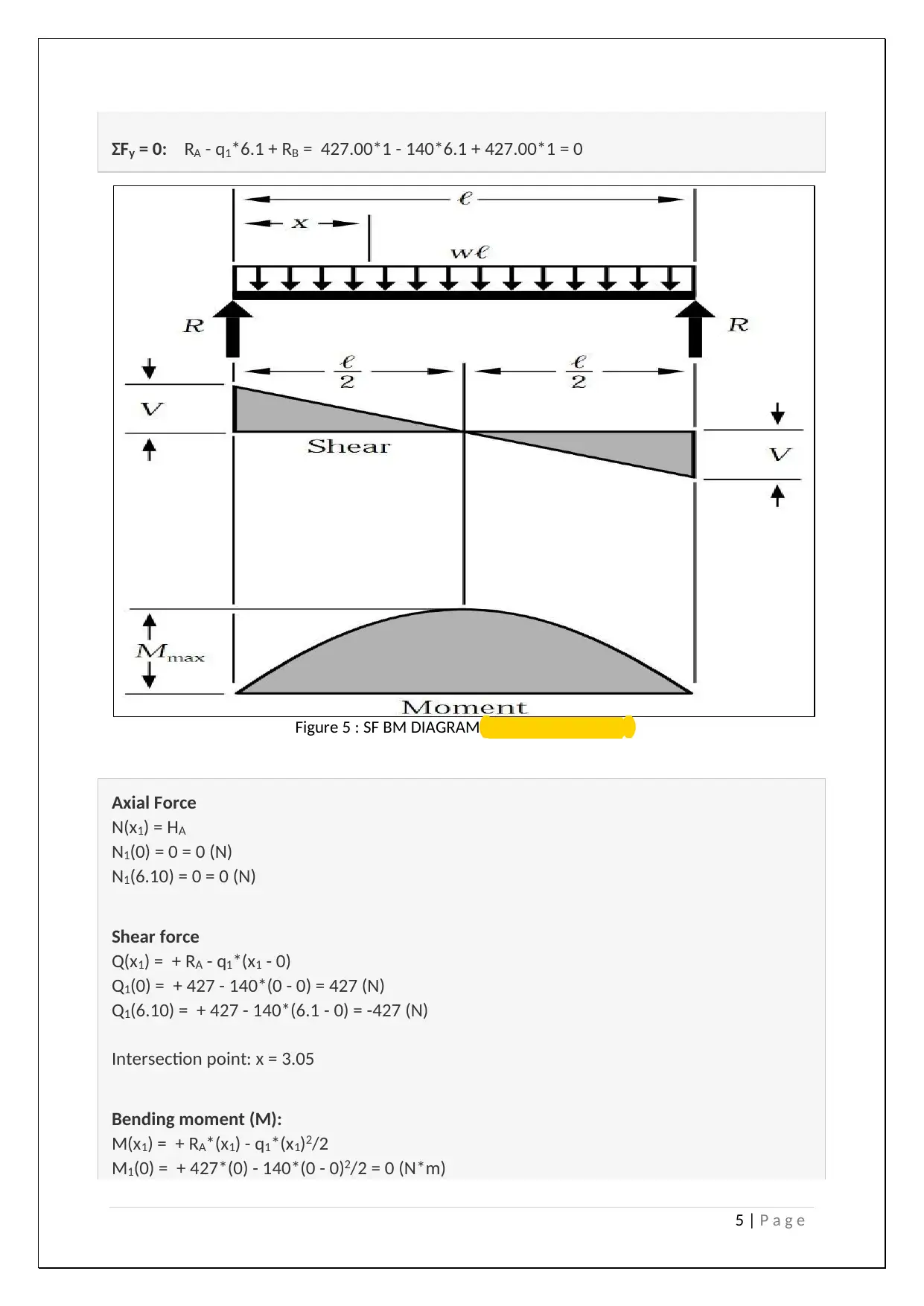
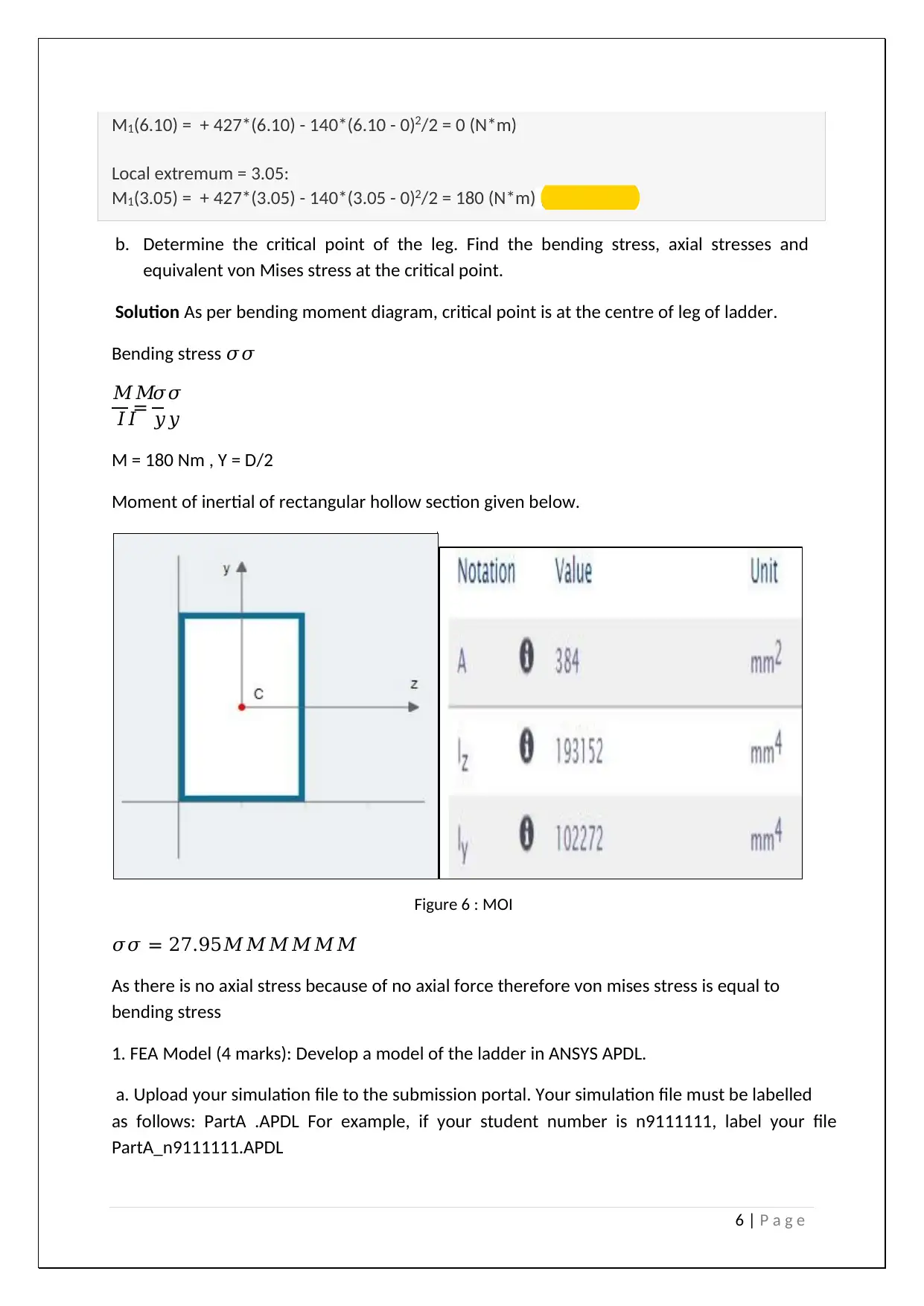
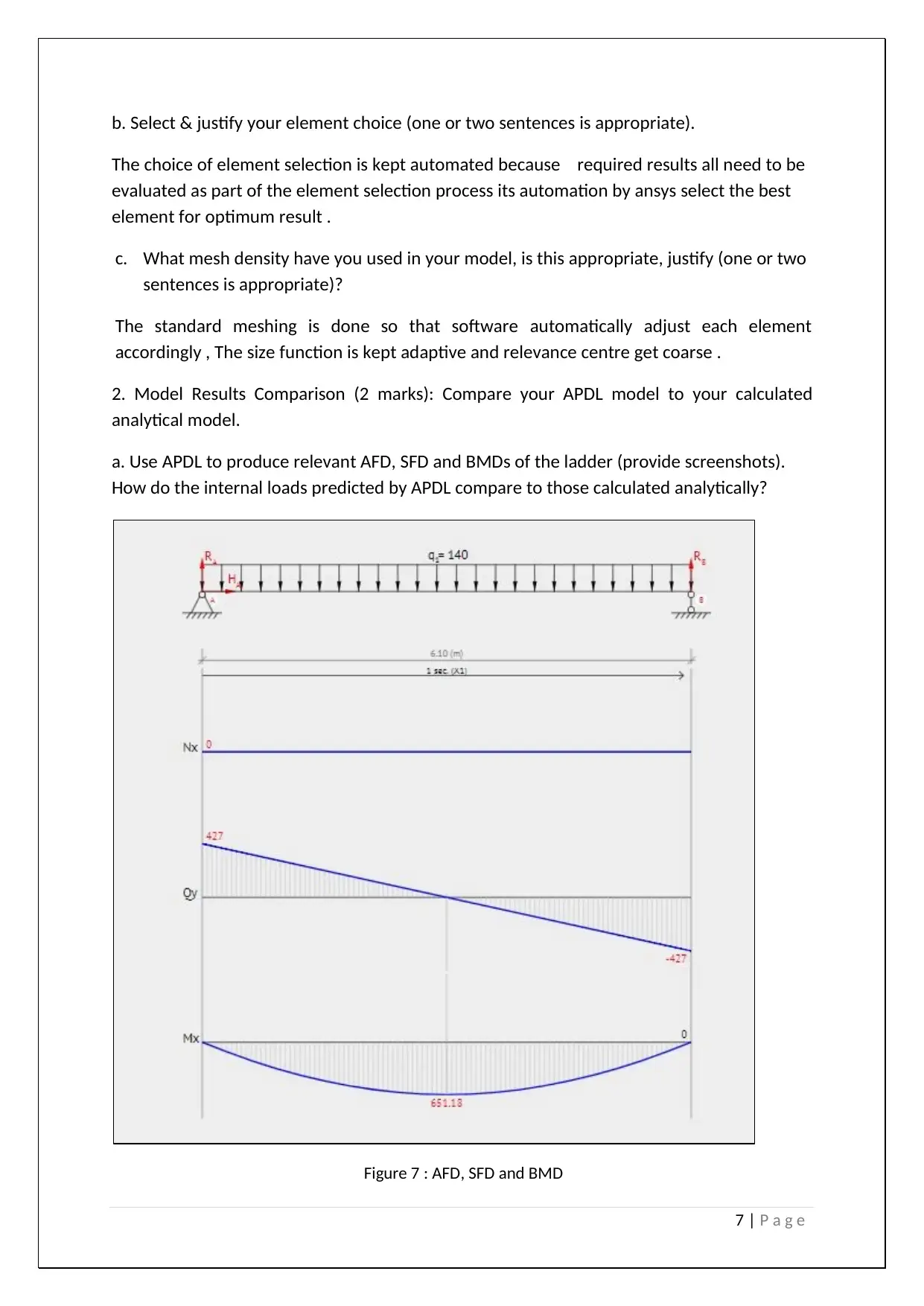
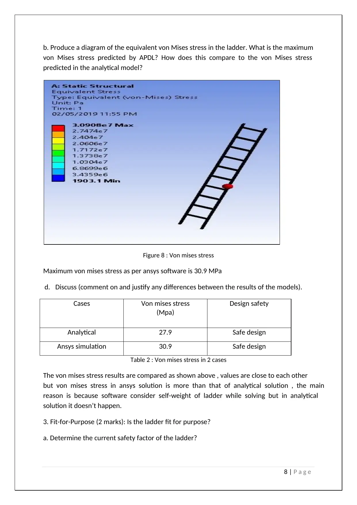
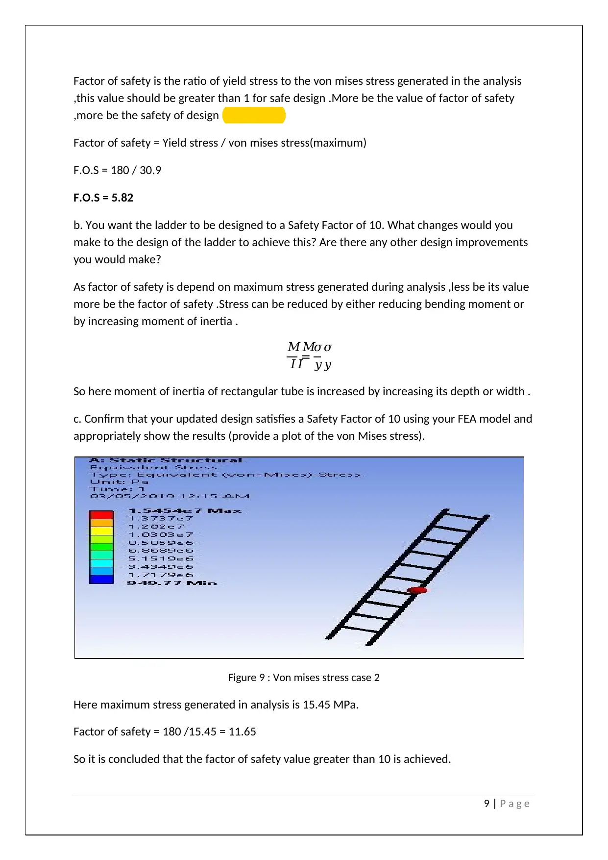
This assignment presents a comprehensive analysis of a ladder design, integrating both analytical calculations and Finite Element Analysis (FEA) using ANSYS APDL. The project begins with defining the ladder's geometry and material properties (6000 series aluminum). The student then performs analytical calculations to determine the Free Body Diagram (FBD), Axial Force Diagram (AFD), Shear Force Diagram (SFD), and Bending Moment Diagram (BMD) for the ladder's legs, considering load conditions such as a person standing on the ladder. Critical points are identified, and bending and von Mises stresses are calculated. The assignment then progresses to FEA modeling using ANSYS APDL, including element selection and meshing justification. Results from the APDL model, including AFD, SFD, BMD, and von Mises stress distributions, are compared with the analytical solutions. Finally, a fit-for-purpose analysis is conducted, determining the current safety factor, suggesting design improvements to achieve a safety factor of 10, and validating the updated design through FEA. The analysis includes detailed comparisons and discussions of any differences between the analytical and FEA results.

1 | P a g e
ASSIGNMENT SOLUTION
LADDER DESIGN
ASSIGNMENT SOLUTION
LADDER DESIGN
Paraphrase This Document
Need a fresh take? Get an instant paraphrase of this document with our AI Paraphraser

2 | P a g e
PROBLEM FORMULATION
In this report, the ladder is needed to be modelled as per given dimensions and then it is
tested on certain load conditions. The results generated by software is compared with
analytical result and then conclude the final result.
Figure 1: MODELLING
MODELLING
The geometry of the ladder is shown in Figure 1a. The ladder has a length of 6.1 m and a
width of 0.5 m. The ladder consists of 10 rungs at a spacing of 0.59 m, starting from the
bottom (leaving 0.2 m from the top rung to the top of the ladder). The rungs are made from
hollow circular sections with an outer diameter of 60 mm and a thickness of 2 mm. The legs
of the ladder are made of hollow rectangular sections with external cross-section
dimensions of 60 mm Γ 40 mm and a thickness of 2 mm. The rungs are welded to the 60 mm
side of the face, such that rungs are orthogonal to the 60 mm side of the legs.

3 | P a g e
After creating the model then material is applied on ladder is 6000 aluminium series. .The
material properties of 6061 aluminium is shown below.
Properties Value Units
Elastic Modulus 70 GN/m^2
Poissonβs Ratio 0.33 N/A
Shear Modulus 145 N/m^2
Density 2700 kg/m^3
Tensile Strength 145 N/m^2
Yield Strength 185 MN/m^2
Thermal Expansion Coefficient 2.4e-005 /K
Thermal Conductivity 170 W/(mΒ·K)
Specific Heat 1300 J/(kgΒ·K)
Table 1: Aluminium Material properties (Grushko, 2016)
According to the selected material for 6000 aluminium for ladder, weight is 6.64 Kilograms
Figure 2: Mass
LOAD CONDITIONS
It is required to model the case where the ladder is leant against a wall, making a 70Β° angle
with the ground. An 85 kg person is standing on the 6th rung of the ladder (measured from
the bottom). The person is centred on the rung with their feet spaced 0.3 m apart, such that
their entire weight is evenly distributed between their feet. The weight of the person
provides a vertical force. For this model assume the ladderβs feet are firmly planted into the
ground, acting like a pinned support, while the top of the ladder acts as a vertical roller
support against the wall.
β This is a preview!β
Do you want full access?
Subscribe today to unlock all pages.

Trusted by 1+ million students worldwide

4 | P a g e
PROJECT REQUIREMENTS
1 You are required to study the loads acting on the legs of the ladder. Produce an analytical
solution for one of the legs of the ladder. Evenly distribute the weight of the person
between the ladderβs legs.
a. Developing a FBD, AFD, SFD and BMD of the leg. Consider the base to be pinned, and
the top to be supported by a vertical roller (as shown in Figure 1b).
Solution
Free body diagram of ladder is subdivided into 2 parts. One is at its base where it is pinned
from its base as shown below (Craig , 2013)
Figure 3 : Support 1
Other is at its top where it is supported by a vertical roller as shown below.
Figure 4 : Support 2
Reaction ,Shear force and bending moment diagram
Ξ£MA = 0:
- q1*6.1*(6.1/2) + RB*6.1 = 0
Ξ£MB = 0:
- RA*6.1 + q1*6.1*(6.1 - 6.1/2) = 0
Reaction
RB = ( q1*6.1*(6.1/2)) / 6.1 = ( 140*6.1*(6.1/2)) / 6.1 = 427.00 (N)
RA = ( q1*6.1*(6.1 - 6.1/2)) / 6.1 = ( 140*6.1*(6.1 - 6.1/2)) / 6.1 = 427.00 (N)
HA = 0 (N)
Paraphrase This Document
Need a fresh take? Get an instant paraphrase of this document with our AI Paraphraser

5 | P a g e
Ξ£Fy = 0: RA - q1*6.1 + RB = 427.00*1 - 140*6.1 + 427.00*1 = 0
Figure 5 : SF BM DIAGRAM (Chaskalovic, 2015 )
Axial Force
N(x1) = HA
N1(0) = 0 = 0 (N)
N1(6.10) = 0 = 0 (N)
Shear force
Q(x1) = + RA - q1*(x1 - 0)
Q1(0) = + 427 - 140*(0 - 0) = 427 (N)
Q1(6.10) = + 427 - 140*(6.1 - 0) = -427 (N)
Intersection point: x = 3.05
Bending moment (M):
M(x1) = + RA*(x1) - q1*(x1)2/2
M1(0) = + 427*(0) - 140*(0 - 0)2/2 = 0 (N*m)

6 | P a g e
M1(6.10) = + 427*(6.10) - 140*(6.10 - 0)2/2 = 0 (N*m)
Local extremum = 3.05:
M1(3.05) = + 427*(3.05) - 140*(3.05 - 0)2/2 = 180 (N*m) (Bedi, 2012).
b. Determine the critical point of the leg. Find the bending stress, axial stresses and
equivalent von Mises stress at the critical point.
Solution As per bending moment diagram, critical point is at the centre of leg of ladder.
Bending stress ππ
ππ
πΌπΌ
= ππ
π¦π¦
M = 180 Nm , Y = D/2
Moment of inertial of rectangular hollow section given below.
Figure 6 : MOI
ππ = 27.95ππππππ
As there is no axial stress because of no axial force therefore von mises stress is equal to
bending stress
1. FEA Model (4 marks): Develop a model of the ladder in ANSYS APDL.
a. Upload your simulation file to the submission portal. Your simulation file must be labelled
as follows: PartA .APDL For example, if your student number is n9111111, label your file
PartA_n9111111.APDL
β This is a preview!β
Do you want full access?
Subscribe today to unlock all pages.

Trusted by 1+ million students worldwide

7 | P a g e
b. Select & justify your element choice (one or two sentences is appropriate).
The choice of element selection is kept automated because required results all need to be
evaluated as part of the element selection process its automation by ansys select the best
element for optimum result .
c. What mesh density have you used in your model, is this appropriate, justify (one or two
sentences is appropriate)?
The standard meshing is done so that software automatically adjust each element
accordingly , The size function is kept adaptive and relevance centre get coarse .
2. Model Results Comparison (2 marks): Compare your APDL model to your calculated
analytical model.
a. Use APDL to produce relevant AFD, SFD and BMDs of the ladder (provide screenshots).
How do the internal loads predicted by APDL compare to those calculated analytically?
Figure 7 : AFD, SFD and BMD
Paraphrase This Document
Need a fresh take? Get an instant paraphrase of this document with our AI Paraphraser

8 | P a g e
b. Produce a diagram of the equivalent von Mises stress in the ladder. What is the maximum
von Mises stress predicted by APDL? How does this compare to the von Mises stress
predicted in the analytical model?
Figure 8 : Von mises stress
Maximum von mises stress as per ansys software is 30.9 MPa
d. Discuss (comment on and justify any differences between the results of the models).
Cases Von mises stress
(Mpa)
Design safety
Analytical 27.9 Safe design
Ansys simulation 30.9 Safe design
Table 2 : Von mises stress in 2 cases
The von mises stress results are compared as shown above , values are close to each other
but von mises stress in ansys solution is more than that of analytical solution , the main
reason is because software consider self-weight of ladder while solving but in analytical
solution it doesnβt happen.
3. Fit-for-Purpose (2 marks): Is the ladder fit for purpose?
a. Determine the current safety factor of the ladder?

9 | P a g e
Factor of safety is the ratio of yield stress to the von mises stress generated in the analysis
,this value should be greater than 1 for safe design .More be the value of factor of safety
,more be the safety of design (Beer ,2015)
Factor of safety = Yield stress / von mises stress(maximum)
F.O.S = 180 / 30.9
F.O.S = 5.82
b. You want the ladder to be designed to a Safety Factor of 10. What changes would you
make to the design of the ladder to achieve this? Are there any other design improvements
you would make?
As factor of safety is depend on maximum stress generated during analysis ,less be its value
more be the factor of safety .Stress can be reduced by either reducing bending moment or
by increasing moment of inertia .
ππ
πΌπΌ
= ππ
π¦π¦
So here moment of inertia of rectangular tube is increased by increasing its depth or width .
c. Confirm that your updated design satisfies a Safety Factor of 10 using your FEA model and
appropriately show the results (provide a plot of the von Mises stress).
Figure 9 : Von mises stress case 2
Here maximum stress generated in analysis is 15.45 MPa.
Factor of safety = 180 /15.45 = 11.65
So it is concluded that the factor of safety value greater than 10 is achieved.
β This is a preview!β
Do you want full access?
Subscribe today to unlock all pages.

Trusted by 1+ million students worldwide

10 | P a g e
REFERNCES
Grushko, Olga; Ovsyannikov, Boris; Ovchinnokov, Viktor (2016). Eskin, D. G. (ed.). Aluminum-
Lithium Alloys: Process Metallurgy, Physical Metallurgy, and Welding. Advances in metallic
alloys. 8. CRC Press/Taylor & Francis Group.
G. Allaire and A. Craig (2013): Numerical Analysis and Optimization: An Introduction to
Mathematical Modelling and Numerical Simulation
J. Chaskalovic (2015) : Finite Elements Methods for Engineering Sciences, Springer Verlag
Ashwani Bedi and Ramsey Dabby (2012). Structure for Architects: A Primer. Canada: John
Wileys and Sons.
Beer, F and Johnson, R (2015): Mechanics of Materials, second edition. McGraw-Hill
1 out of 10
Your All-in-One AI-Powered Toolkit for Academic Success.
Β +13062052269
info@desklib.com
Available 24*7 on WhatsApp / Email
Unlock your academic potential
Copyright Β© 2020β2025 A2Z Services. All Rights Reserved. Developed and managed by ZUCOL.

