EL2241: Relaxation Oscillator Circuit Design, Simulation and Testing
VerifiedAdded on 2023/04/26
|6
|1211
|455
Report
AI Summary
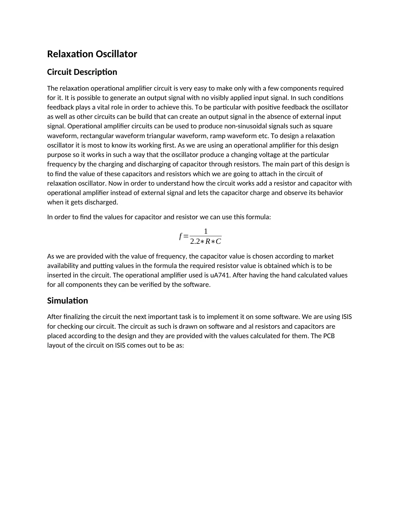
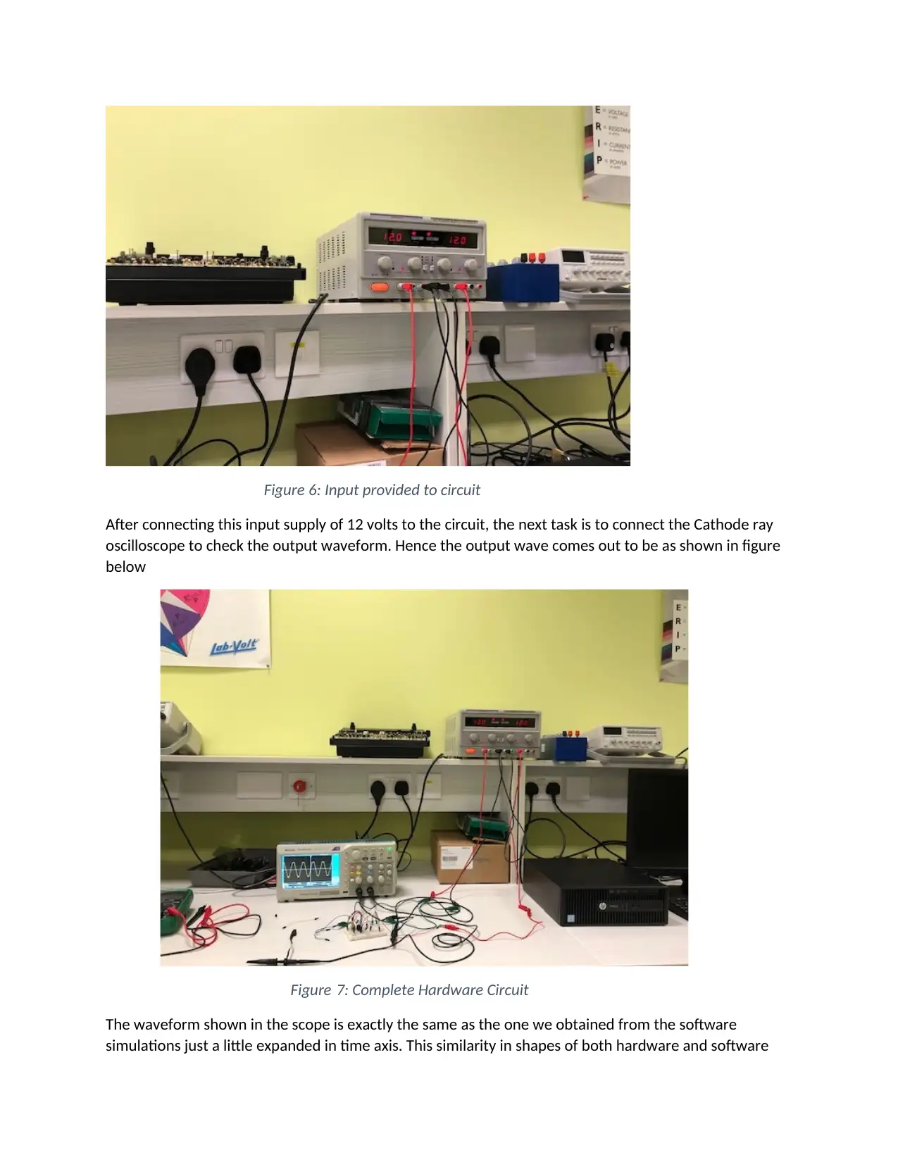
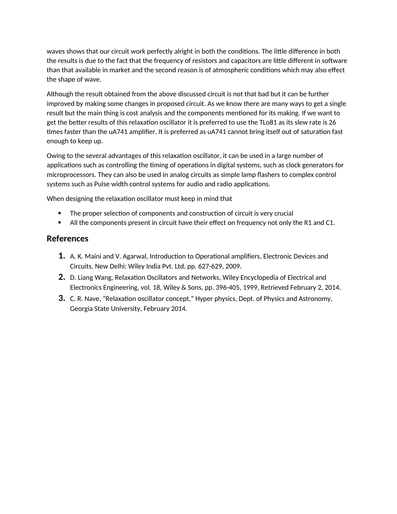
This report details the design, simulation, and hardware implementation of a relaxation oscillator circuit using the uA741 operational amplifier. The design process involves calculating resistor and capacitor values to achieve a specific operational frequency, followed by simulation using ISIS software to verify the circuit's functionality. The PCB layout is created using ARES, ensuring it meets size requirements. Hardware testing is conducted on a breadboard, and the output waveform is compared with simulation results. The report also discusses potential improvements using a TLo81 amplifier and highlights applications of relaxation oscillators in digital and analog systems. References to relevant literature are provided to support the design and analysis.
1 out of 6
Related Documents


Your All-in-One AI-Powered Toolkit for Academic Success.
+13062052269
info@desklib.com
Available 24*7 on WhatsApp / Email
![[object Object]](/_next/static/media/star-bottom.7253800d.svg)
Copyright © 2020–2026 A2Z Services. All Rights Reserved. Developed and managed by ZUCOL.