ELEC120 Design Assignment: Induction Loop for Bicycle Detection
VerifiedAdded on 2022/08/26
|22
|3264
|98
Report
AI Summary
This report addresses the City Council's initiative to enhance bicycle travel within the city by improving traffic light sensor responsiveness. The study investigates various traffic detection systems, focusing on inductive loop detectors (ILDs) and their application in detecting bicycles, considering the use of carbon fiber in modern bicycles. It examines the working principles of ILDs, highlighting their cost-effectiveness and efficiency. The report analyzes different loop designs, including rectangular, circular, and quadrupole configurations, to determine the optimal shape for bicycle detection. It also delves into the benefits and limitations of each design, considering factors like magnetic field intensity, inductance, and installation methods. The study recommends the quadrupole loop design as the most suitable for detecting bicycles due to its sensitivity and ability to detect low-conductivity materials. Furthermore, it touches upon the advantages and disadvantages of other loop designs, such as the triangular loop design and the dipole loop design. Finally, the report concludes that the quadrupole loop is the best option for bicycle detection and that induction loop technology is also helpful in other areas, such as metal detection and classification of vehicles. The report is a solution for ELEC120 Design Assignment and is contributed by a student to be published on the website Desklib.

Physics
Paraphrase This Document
Need a fresh take? Get an instant paraphrase of this document with our AI Paraphraser
Abstract:-
Inductive loop detection is also called as inductive loop traffic detectors. These detectors sense the
vehicles arriving or passing at a central point of the road. An inductive loop system measures the
amplitude variation and the vehicle count. The main problem of this research is that the sensor of the
traffic light controller not detects the bicycle. The main aim of this study is to find the best inductive
loop for the design of a bicycle. So that loop can identify the small vehicle for example bicycle. In this
study, different loop method design is used to analyze, which method is best for all aspect.
1. Introduction:-
Bicycle riding improves mental and physical health. It is environmentally friendly. Physical exercise
improves mental health. Bicycles riding can increase the mobility in many groups of the population.
According to The City Council, a large number of people should use bicycle to travel in the city. It
reduces the wear on the road, and provides long term money saving. The main highlighted problem is
that traffic light sensors not detect cyclists. This report contains recommendations and evaluation for
the old system and replacing them with a new, more eco-friendly system.
2. Background of the Research:-
The first type of the sensors is the magneto-meter sensors or passive magnetic sensors; these sensors
can be permanently mounted with the road holes or can be fixed on the road surface. The unit
communicates to the near base station use the wires buried within the street or remote sensors for
communication purposes. The sensor provides the features of the or elliptically offset zone at the
location, also called a blue area. The other type of sensors utilizes pneumatic tubes which are extended
across the carriageway and attached at the both ends of kerb side. These systems are designed on the
temporary basis. Due to the breakable nature of the tube it can easily be torn or damaged by the or fast
moving or heavy vehicles. The other type of detector is called IDL (inductive detector loops) made up of
the coated with the wire coils and buried in grooves cut off the road surface. These sensors are sealed
with the bituminous filler (Alliance 2012). A buried cable with the circle transmits the information to a
roadside handling unit. The location zone or area for inductive circle sensors depends upon the cut
shape of the circle openings. The zones or area do not depend upon the slot dimensions, and it depends
upon the overall sensitivity of the system. IDL is mature and cheap technology. The spine locator
introduces to control most of the activities of the control framework. The fourth type of intrusive system
is WIM (Weigh-In-Motion); it is based on the piezoelectric sensor. It is also called fiber-optic or bending
–plate and this type of network connected to the road. These systems are generally not used and are
utilized in particular locations for authorization or get to control. These systems are usually coupled with
other frameworks, either non-intrusive or intrusive, to provides extra cross-checks on collected
information (Chakraborty, Jana, Ray and Debnath, 2015).
3. Benefits of the Induction Loop system:-
ILDs (Inductive loop detectors) are the widely used traffic sensors. It is widely used for the detection of
vehicles. Presently, for Lane to Lane detection, ILD requires separate cables for connecting the loops. It
also requires the independent detector channels and acquisition systems to process the data (Yogesh,
Sharma, and Vanajakshi, 2018). The advantage of the inductive loop system is that it is a very cost
effective and efficient technology. So, every dynamic traffic control system uses IDL data in the world.
Mechanical wear not faced by these systems moving parts. It can detect vehicles with proximity.
4. Working of Induction loop for detection of traffic:-
IDL is a metal detector system that senses the object and measures the field change when the object
passes through it. Once a vehicle moves over a circular sensor, then the change in the circle field permits
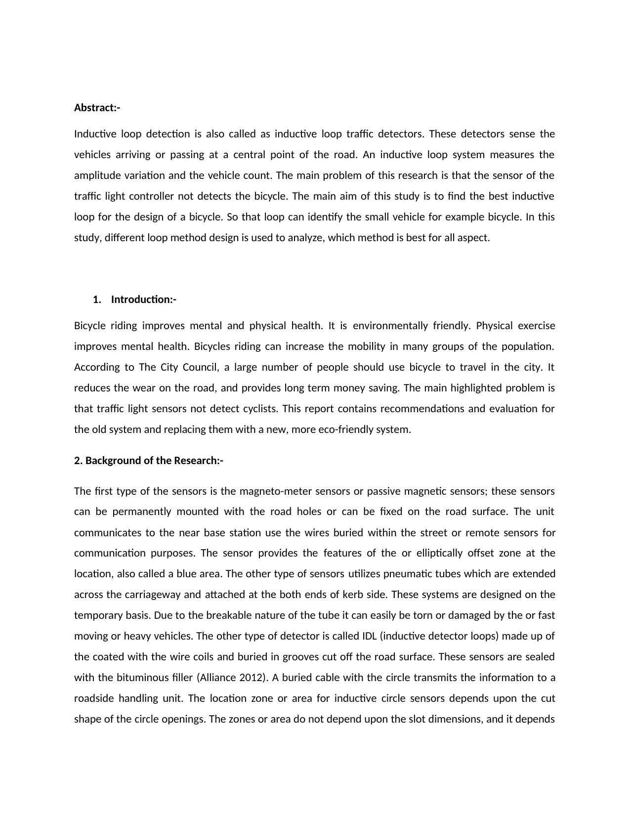
the detection device to sense the presence of the vehicle. Mainly three types of the inductive loop
structure used to sense the vehicles. Figure 1 represents the small loop structure, which is used to
detect small vehicles such as bike, motor, and bicycle. The loop 2 Figure detects large vehicles such as
buses and cars. The third type of loop is a combination of loop1 and loop2, also sense the heavy
vehicles. If the small vehicle passes through loop 2, then no consideration changes occur in the loop
inductance, which leads to the miss detection.
introduces to control most of the activities of the control framework. The fourth type of intrusive system
is WIM (Weigh-In-Motion); it is based on the piezoelectric sensor. It is also called fiber-optic or bending
–plate and this type of network connected to the road. These systems are generally not used and are
utilized in particular locations for authorization or get to control. These systems are usually coupled with
other frameworks, either non-intrusive or intrusive, to provides extra cross-checks on collected
information (Chakraborty, Jana, Ray and Debnath, 2015).
3. Benefits of the Induction Loop system:-
ILDs (Inductive loop detectors) are the widely used traffic sensors. It is widely used for the detection of
vehicles. Presently, for Lane to Lane detection, ILD requires separate cables for connecting the loops. It
also requires the independent detector channels and acquisition systems to process the data (Yogesh,
Sharma, and Vanajakshi, 2018). The advantage of the inductive loop system is that it is a very cost
effective and efficient technology. So, every dynamic traffic control system uses IDL data in the world.
Mechanical wear not faced by these systems moving parts. It can detect vehicles with proximity.
4. Working of Induction loop for detection of traffic:-
IDL is a metal detector system that senses the object and measures the field change when the object
passes through it. Once a vehicle moves over a circular sensor, then the change in the circle field permits
the detection device to sense the presence of the vehicle. Mainly three types of the inductive loop
structure used to sense the vehicles. Figure 1 represents the small loop structure, which is used to
detect small vehicles such as bike, motor, and bicycle. The loop 2 Figure detects large vehicles such as
buses and cars. The third type of loop is a combination of loop1 and loop2, also sense the heavy
vehicles. If the small vehicle passes through loop 2, then no consideration changes occur in the loop
inductance, which leads to the miss detection.
⊘ This is a preview!⊘
Do you want full access?
Subscribe today to unlock all pages.
Trusted by 1+ million students worldwide
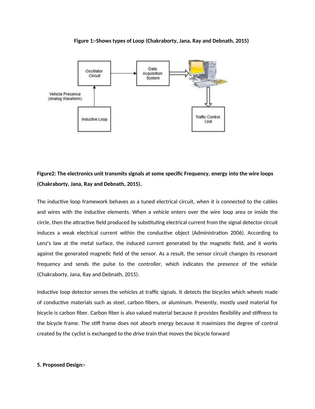
Figure 1:-Shows types of Loop (Chakraborty, Jana, Ray and Debnath, 2015)
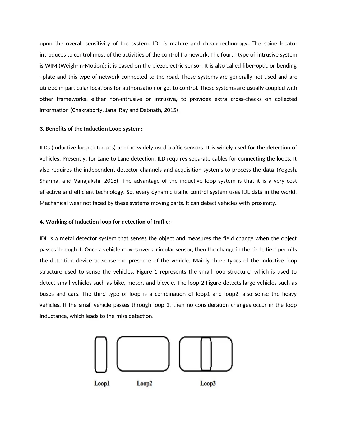
Figure2: The electronics unit transmits signals at some specific Frequency, energy into the wire loops
(Chakraborty, Jana, Ray and Debnath, 2015).
The inductive loop framework behaves as a tuned electrical circuit, when it is connected to the cables
and wires with the inductive elements. When a vehicle enters over the wire loop area or inside the
circle, then the attractive field produced by substituting electrical current from the signal detector circuit
induces a weak electrical current within the conductive object (Administration 2006). According to
Lenz's law at the metal surface, the induced current generated by the magnetic field, and it works
against the generated magnetic field of the sensor. As a result, the sensor circuit changes its resonant
frequency and sends the pulse to the controller, which indicates the presence of the vehicle
(Chakraborty, Jana, Ray and Debnath, 2015).
Inductive loop detector senses the vehicles at traffic signals. It detects the bicycles which wheels made
of conductive materials such as steel, carbon fibers, or aluminum. Presently, mostly used material for
bicycle is carbon fiber. Carbon fiber is also valued material because it provides flexibility and stiffness to
the bicycle frame. The stiff frame does not absorb energy because It maximizes the degree of control
created by the cyclist is exchanged to the drive train that moves the bicycle forward
5. Proposed Design:-
Paraphrase This Document
Need a fresh take? Get an instant paraphrase of this document with our AI Paraphraser
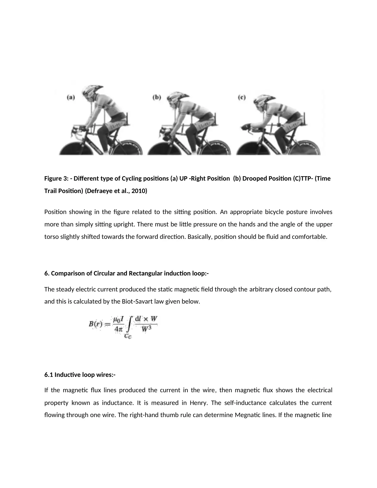
Figure 3: - Different type of Cycling positions (a) UP -Right Position (b) Drooped Position (C)TTP- (Time
Trail Position) (Defraeye et al., 2010)
Position showing in the figure related to the sitting position. An appropriate bicycle posture involves
more than simply sitting upright. There must be little pressure on the hands and the angle of the upper
torso slightly shifted towards the forward direction. Basically, position should be fluid and comfortable.
6. Comparison of Circular and Rectangular induction loop:-
The steady electric current produced the static magnetic field through the arbitrary closed contour path,
and this is calculated by the Biot Savart law given below.‐
6.1 Inductive loop wires:-
If the magnetic flux lines produced the current in the wire, then magnetic flux shows the electrical
property known as inductance. It is measured in Henry. The self-inductance calculates the current
flowing through one wire. The right-hand thumb rule can determine Megnatic lines. If the magnetic line

of the coil is greater than the diameter. Then magnetic flux inside the loop will be uniform except the
ends. The formula gives it
6.1.1Circular loop:-Radius of the circular loop is r, and electric current is I.
Figure 4:- Circular Loop and Rectangular loop geometry (Yogesh, Sharma, and Vanajakshi, 2018)
In the conductor path infinitesimal segment components are:
The tiny segment components in the conductor path and the coordinates of W vector are, for each loop
side:
The magnetic field is calculated by three parts x, y, and z.
⊘ This is a preview!⊘
Do you want full access?
Subscribe today to unlock all pages.
Trusted by 1+ million students worldwide

6.1.2 Rectangular loop:-
The lengths of both sides are equal, and electric current is I.
The magnetic field can be calculated by the given formula.
The lengths of both sides are equal, and electric current is I.
The magnetic field can be calculated by the given formula.
Paraphrase This Document
Need a fresh take? Get an instant paraphrase of this document with our AI Paraphraser
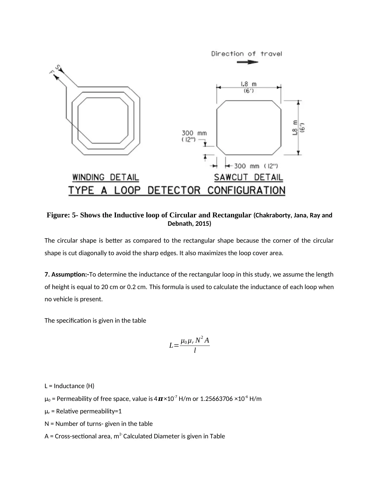
Figure: 5- Shows the Inductive loop of Circular and Rectangular (Chakraborty, Jana, Ray and
Debnath, 2015)
The circular shape is better as compared to the rectangular shape because the corner of the circular
shape is cut diagonally to avoid the sharp edges. It also maximizes the loop cover area.
7. Assumption:-To determine the inductance of the rectangular loop in this study, we assume the length
of height is equal to 20 cm or 0.2 cm. This formula is used to calculate the inductance of each loop when
no vehicle is present.
The specification is given in the table
L= μ0 μr N2 A
l
L = Inductance (H)
μ0 = Permeability of free space, value is 4𝝅×10-7 H/m or 1.25663706 ×10⁻⁶ H/m
μr = Relative permeability=1
N = Number of turns- given in the table
A = Cross-sectional area, m2- Calculated Diameter is given in Table
l = length of loop- Given in the Table
8. To detect the bicycle best shape of Induction Loop Sensor:-
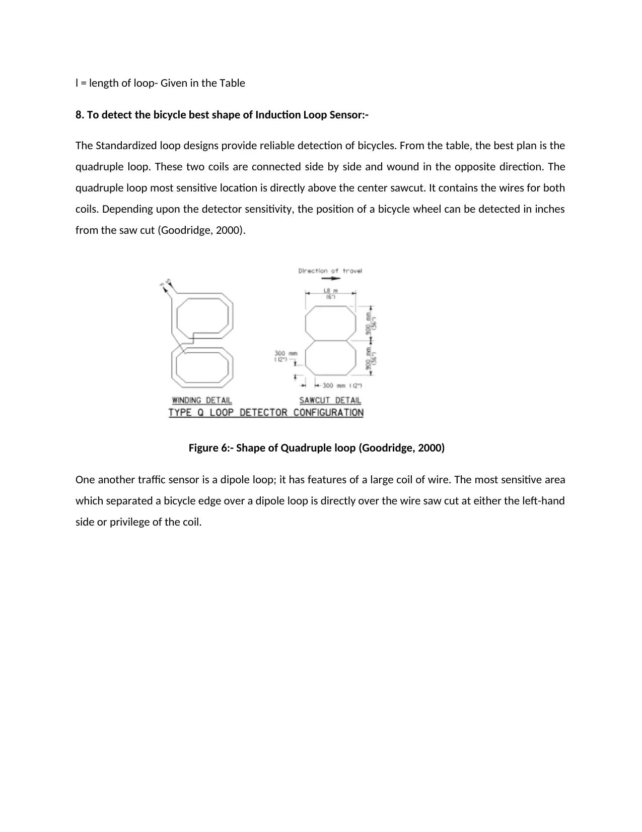
The Standardized loop designs provide reliable detection of bicycles. From the table, the best plan is the
quadruple loop. These two coils are connected side by side and wound in the opposite direction. The
quadruple loop most sensitive location is directly above the center sawcut. It contains the wires for both
coils. Depending upon the detector sensitivity, the position of a bicycle wheel can be detected in inches
from the saw cut (Goodridge, 2000).
Figure 6:- Shape of Quadruple loop (Goodridge, 2000)
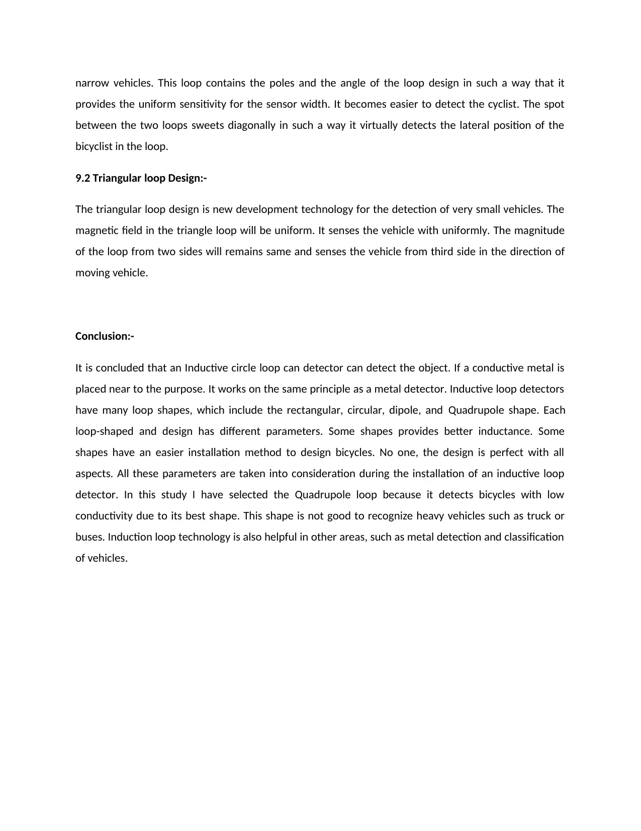
One another traffic sensor is a dipole loop; it has features of a large coil of wire. The most sensitive area
which separated a bicycle edge over a dipole loop is directly over the wire saw cut at either the left-hand
side or privilege of the coil.
8. To detect the bicycle best shape of Induction Loop Sensor:-
The Standardized loop designs provide reliable detection of bicycles. From the table, the best plan is the
quadruple loop. These two coils are connected side by side and wound in the opposite direction. The
quadruple loop most sensitive location is directly above the center sawcut. It contains the wires for both
coils. Depending upon the detector sensitivity, the position of a bicycle wheel can be detected in inches
from the saw cut (Goodridge, 2000).
Figure 6:- Shape of Quadruple loop (Goodridge, 2000)
One another traffic sensor is a dipole loop; it has features of a large coil of wire. The most sensitive area
which separated a bicycle edge over a dipole loop is directly over the wire saw cut at either the left-hand
side or privilege of the coil.
⊘ This is a preview!⊘
Do you want full access?
Subscribe today to unlock all pages.
Trusted by 1+ million students worldwide
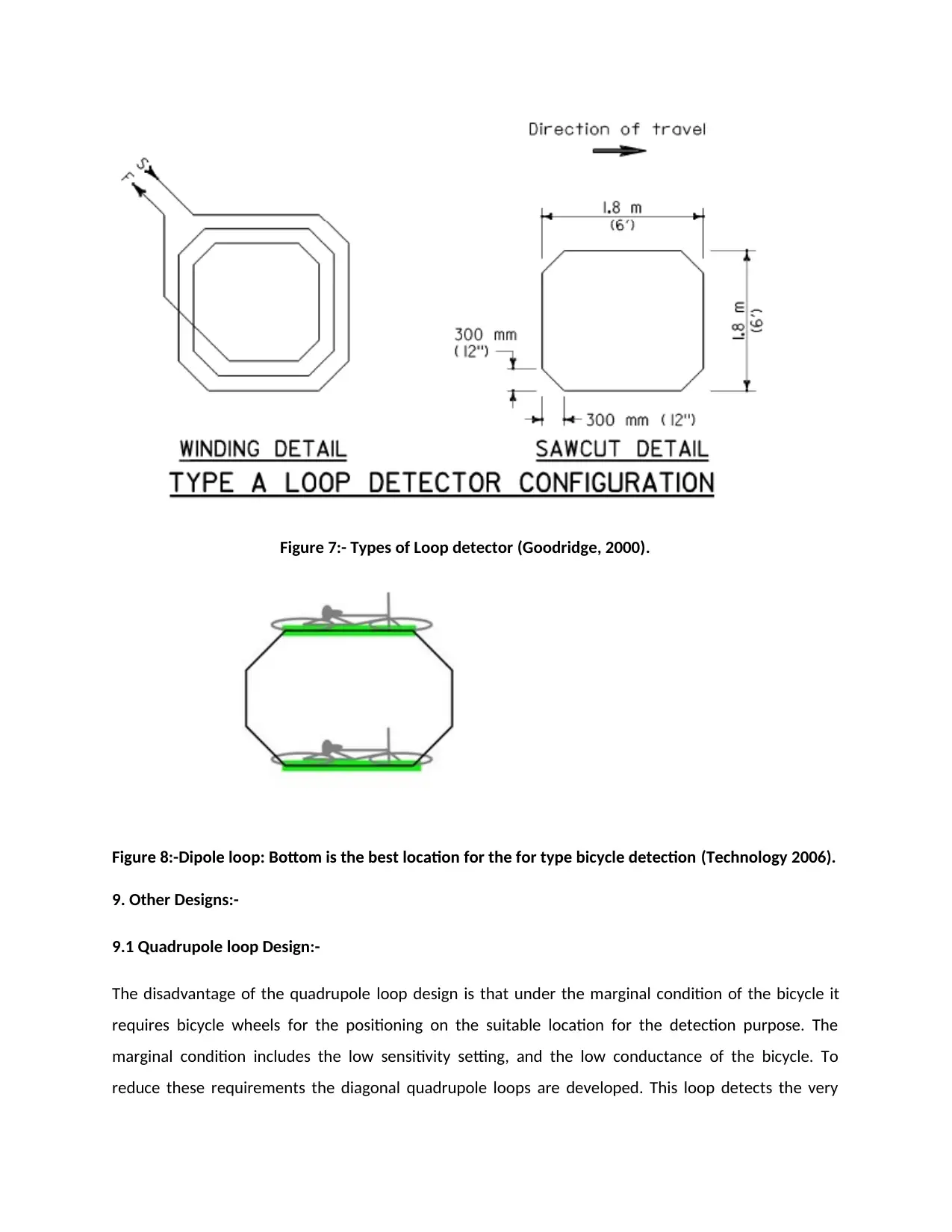
Figure 7:- Types of Loop detector (Goodridge, 2000).
Figure 8:-Dipole loop: Bottom is the best location for the for type bicycle detection (Technology 2006).
9. Other Designs:-
9.1 Quadrupole loop Design:-
The disadvantage of the quadrupole loop design is that under the marginal condition of the bicycle it
requires bicycle wheels for the positioning on the suitable location for the detection purpose. The
marginal condition includes the low sensitivity setting, and the low conductance of the bicycle. To
reduce these requirements the diagonal quadrupole loops are developed. This loop detects the very
Paraphrase This Document
Need a fresh take? Get an instant paraphrase of this document with our AI Paraphraser
narrow vehicles. This loop contains the poles and the angle of the loop design in such a way that it
provides the uniform sensitivity for the sensor width. It becomes easier to detect the cyclist. The spot
between the two loops sweets diagonally in such a way it virtually detects the lateral position of the
bicyclist in the loop.
9.2 Triangular loop Design:-
The triangular loop design is new development technology for the detection of very small vehicles. The
magnetic field in the triangle loop will be uniform. It senses the vehicle with uniformly. The magnitude
of the loop from two sides will remains same and senses the vehicle from third side in the direction of
moving vehicle.
Conclusion:-
It is concluded that an Inductive circle loop can detector can detect the object. If a conductive metal is
placed near to the purpose. It works on the same principle as a metal detector. Inductive loop detectors
have many loop shapes, which include the rectangular, circular, dipole, and Quadrupole shape. Each
loop-shaped and design has different parameters. Some shapes provides better inductance. Some
shapes have an easier installation method to design bicycles. No one, the design is perfect with all
aspects. All these parameters are taken into consideration during the installation of an inductive loop
detector. In this study I have selected the Quadrupole loop because it detects bicycles with low
conductivity due to its best shape. This shape is not good to recognize heavy vehicles such as truck or
buses. Induction loop technology is also helpful in other areas, such as metal detection and classification
of vehicles.
References:-
Administration, F. (2006) Federal Highway Administration Research and Technology Coordinating,
Developing, and Delivering Highway Transportation Innovations. Available from:
https://www.fhwa.dot.gov/publications/research/operations/its/06108/01.cfm [Accessed 03/08/2016 ].
Alliance, N. (2012) Background Paper: Sensors for Bicycle Detection at Traffic Signals. Available from:
http://www.bikewalknc.org/wp-content/uploads/2018/02/Background-Paper-on-Bicycle-Detection.pdf
[Accessed February 18, 2012 ].
Chakraborty, S., Jana, A., Ray, P., and Debnath, G., 2015. An Approach towards Development of a Traffic
Control System with Density Sensor by Using IR Transmitter-Receiver and Inductive Loop Detector.
Journal of the Association of Engineers, India, 85(3-4), p.40.
Defraeye, T., Blocken, B., Koninckx, E., Hespel, P. and Carmeliet, J., 2010. Aerodynamic study of different
cyclist positions: CFD analysis and full-scale wind-tunnel tests. Journal of Biomechanics, 43(7), pp.1262-
1268.
Goodridge,, S. (2000) Detection of Bicycles by Quadrupole Loops at Demand-Actuated Traffic Signals.
Available from: http://humantransport.org/ncbikeed/?page_id=44 [Accessed 2000 ].
Kidarsa, R., Pande, T., Vanjari, S., Krogmeier, J. and Bullock, D., 2006. Design Considerations for
Detecting Bicycles with Inductive Loop Detectors. Transportation Research Record: Journal of the
Transportation Research Board, 1978(1), pp.1-7.
Technology, F. (2006) Chapter 1, Traffic Detector Handbook: Third Edition—Volume I CHAPTER 1.
INTRODUCTION. Available from:
https://www.fhwa.dot.gov/publications/research/operations/its/06108/01.cfm [Accessed 03/08/2016 ].
Yogesh, G., Sharma, A. and Vanajakshi, L., 2018. An Improved Inductive Loop Detector Design for
Efficient Traffic Signal Operations and Leaner Space Requirements. Transportation Research Record:
Journal of the Transportation Research Board, 2672(18), pp.143-153.
⊘ This is a preview!⊘
Do you want full access?
Subscribe today to unlock all pages.
Trusted by 1+ million students worldwide
1 out of 22

Your All-in-One AI-Powered Toolkit for Academic Success.
+13062052269
info@desklib.com
Available 24*7 on WhatsApp / Email
![[object Object]](/_next/static/media/star-bottom.7253800d.svg)
Unlock your academic potential
Copyright © 2020–2026 A2Z Services. All Rights Reserved. Developed and managed by ZUCOL.