ELEC2141 Digital Circuit Design Assignment: Sprinkler & Comparator
VerifiedAdded on 2023/04/06
|17
|1598
|371
Homework Assignment
AI Summary
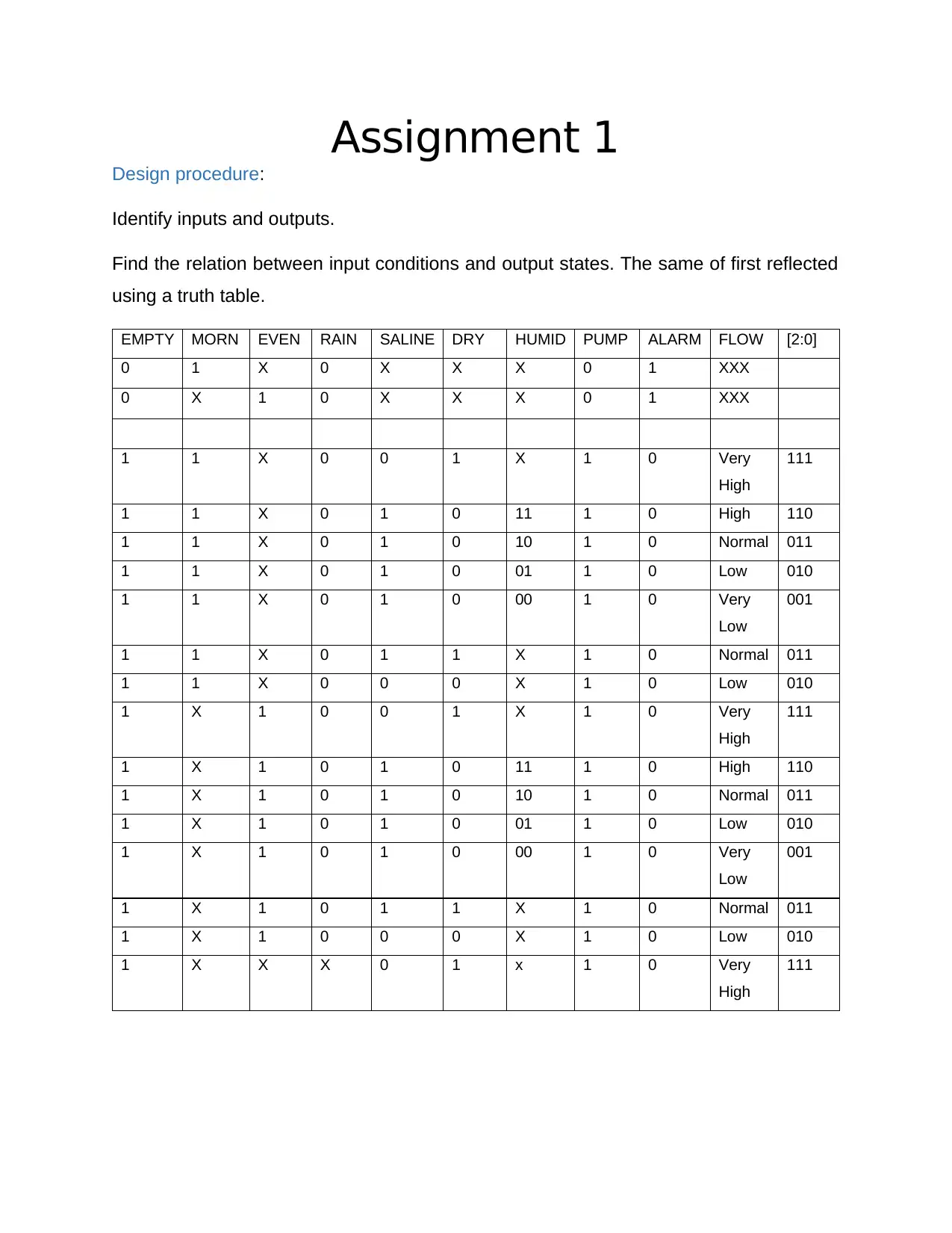
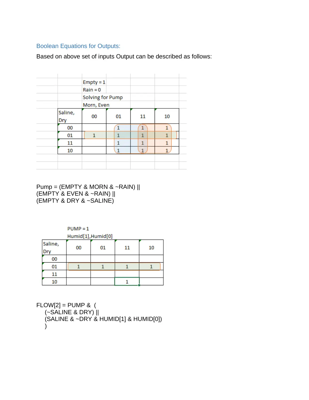
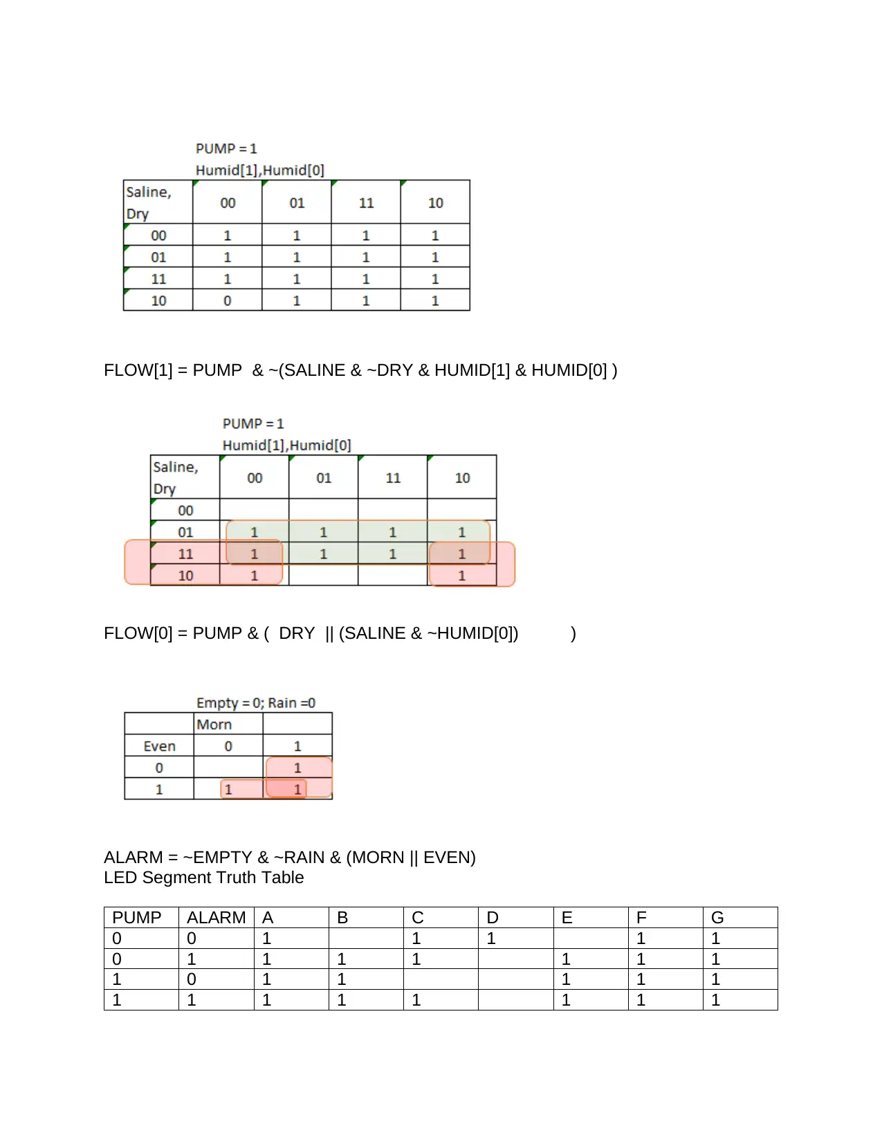
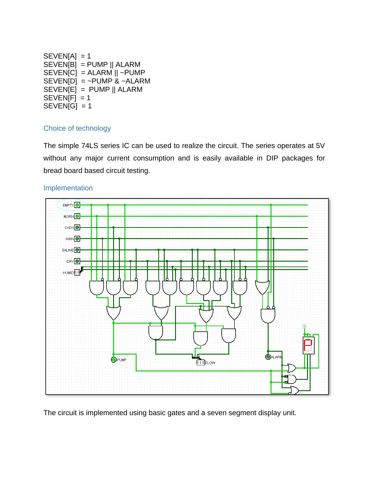
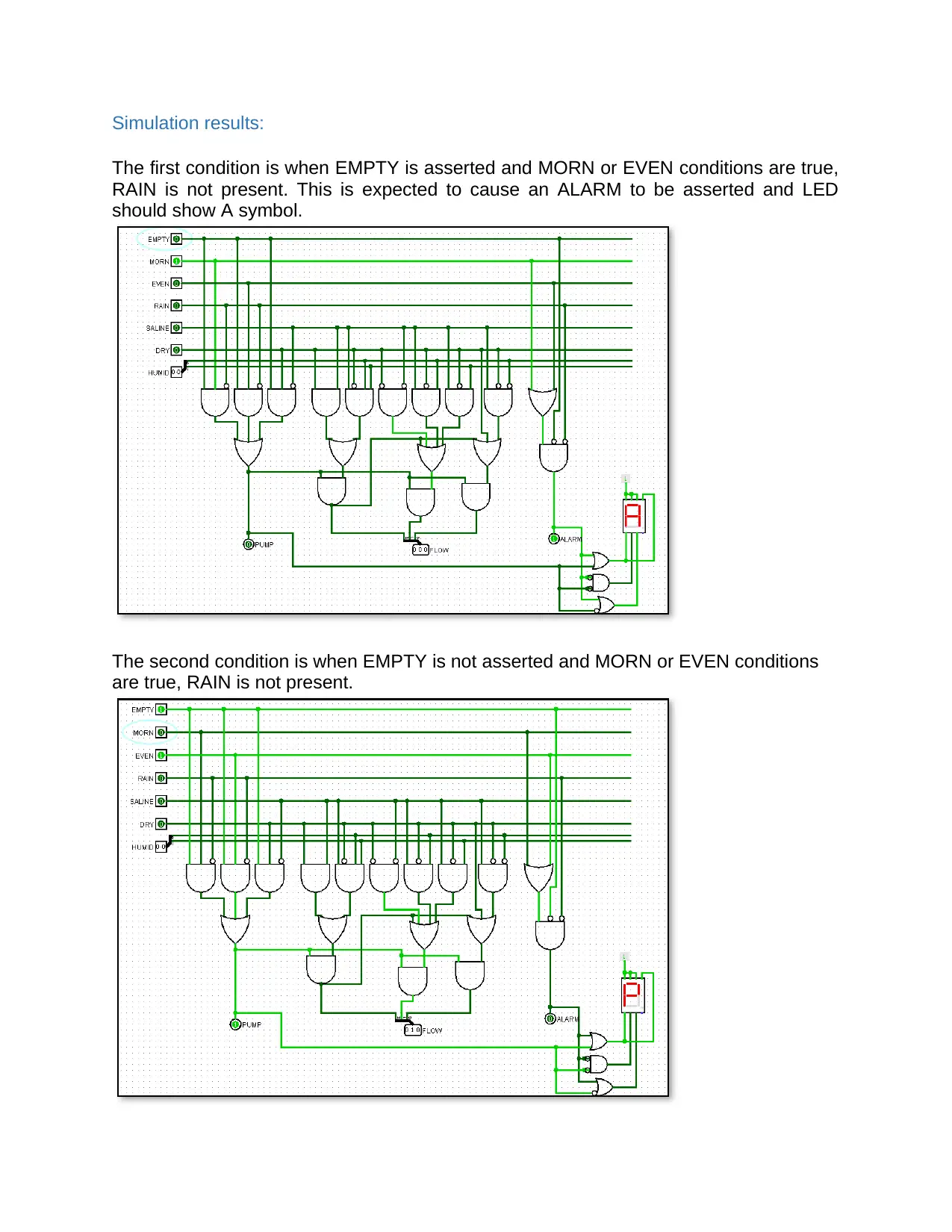
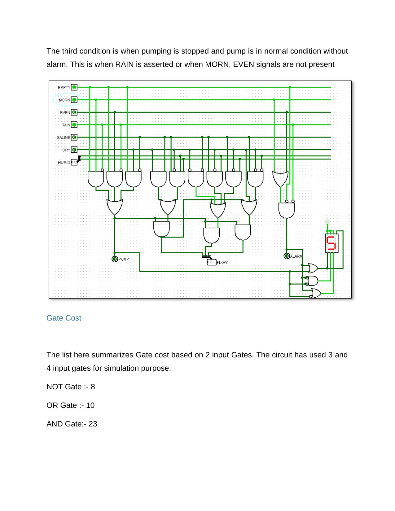
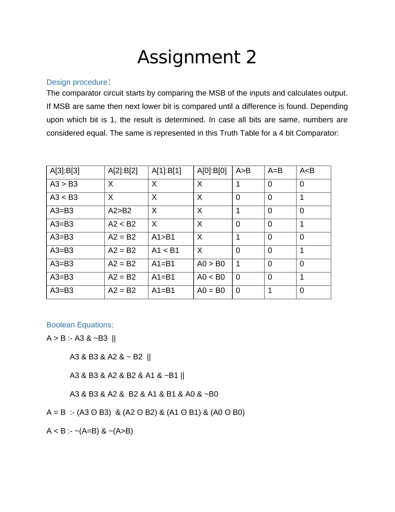
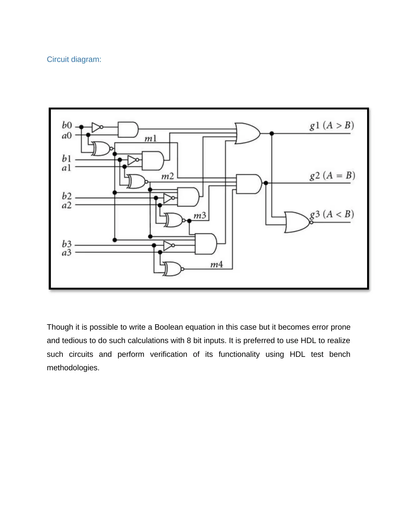
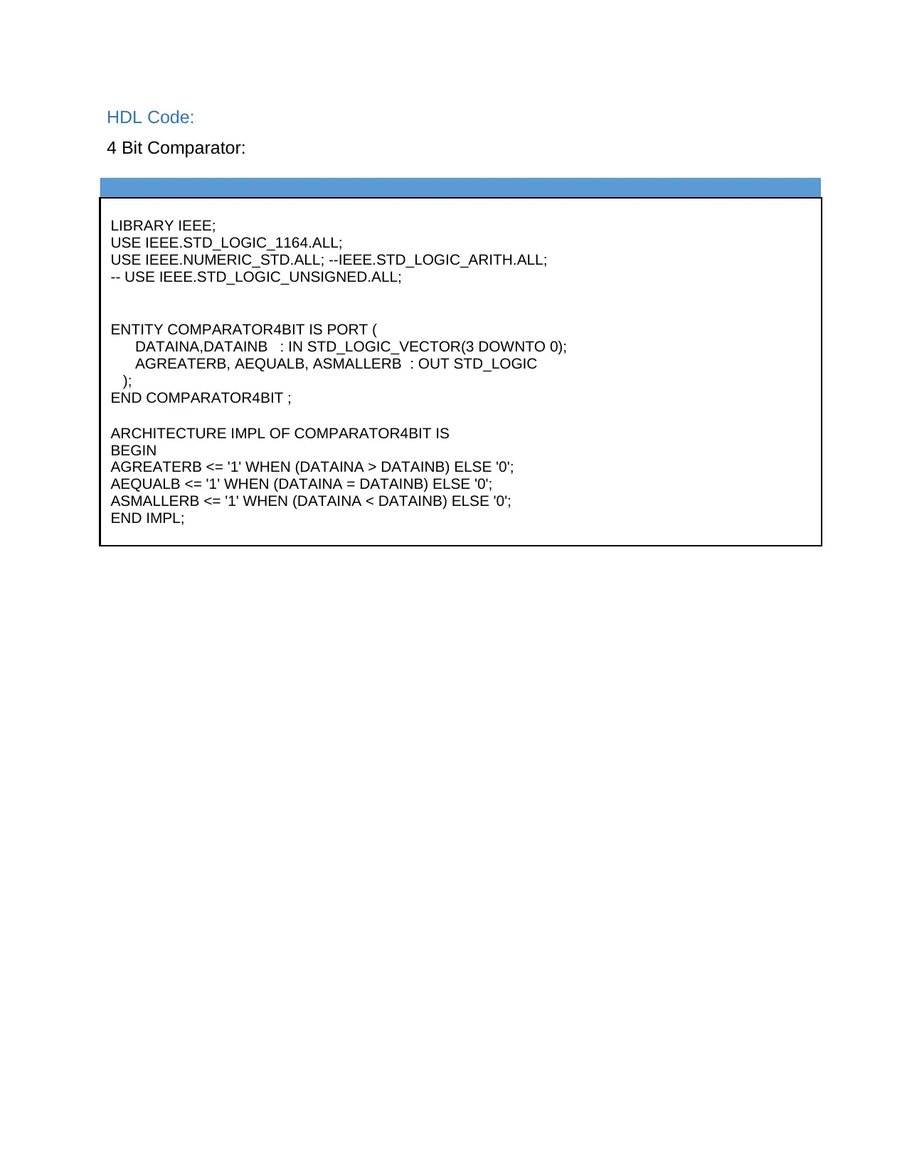
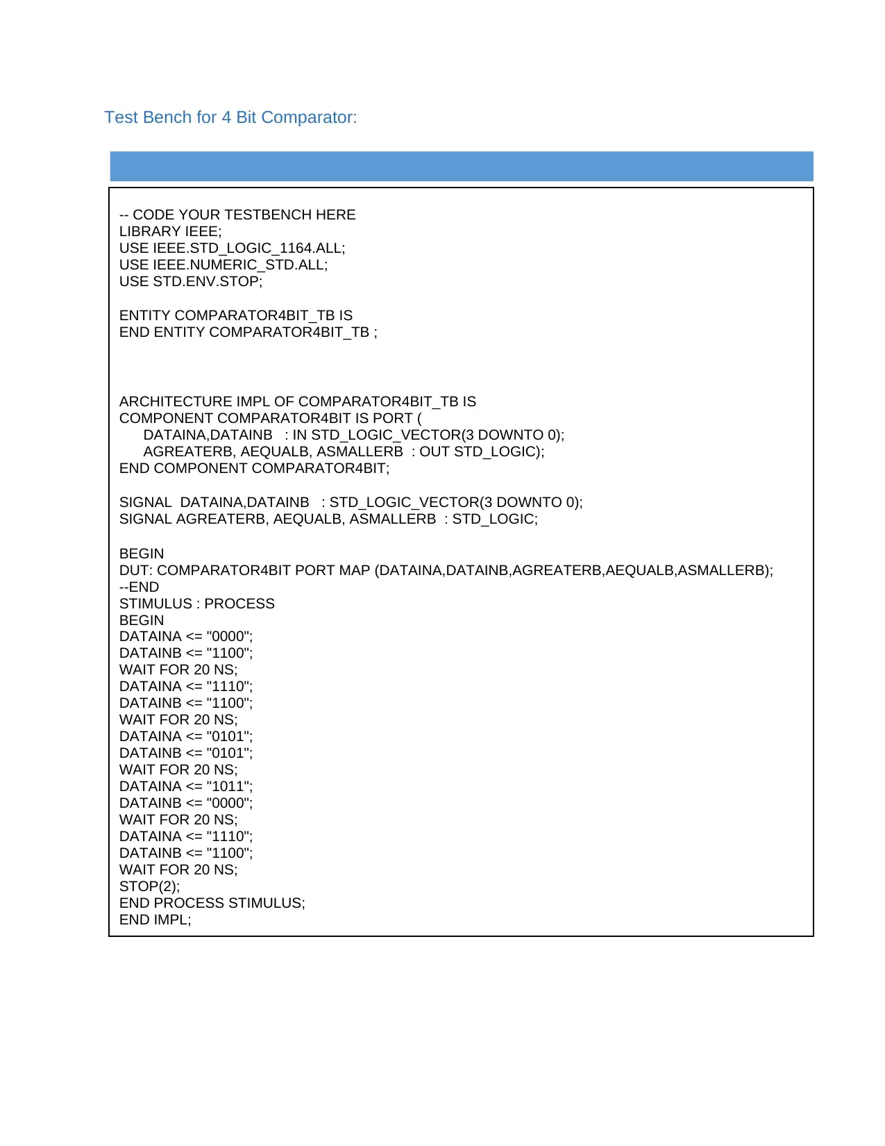
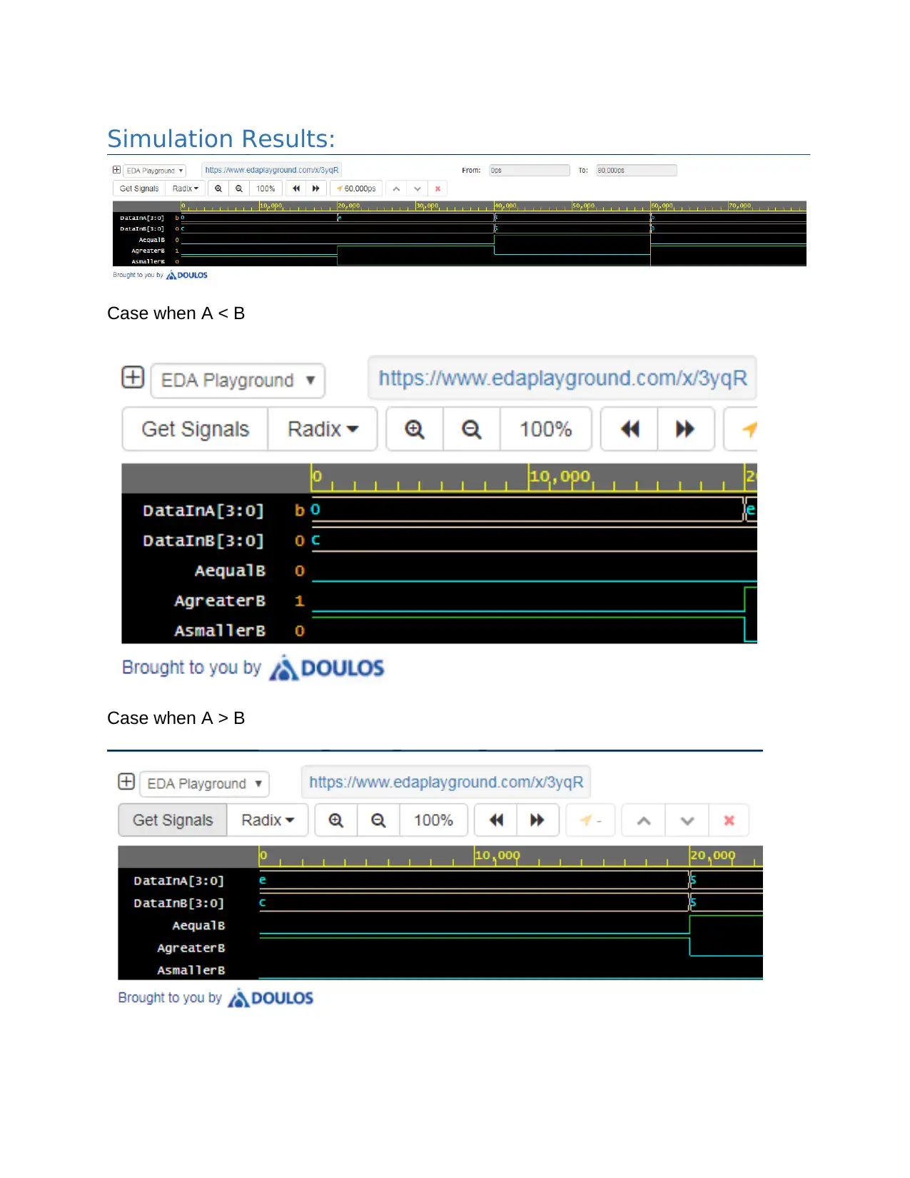
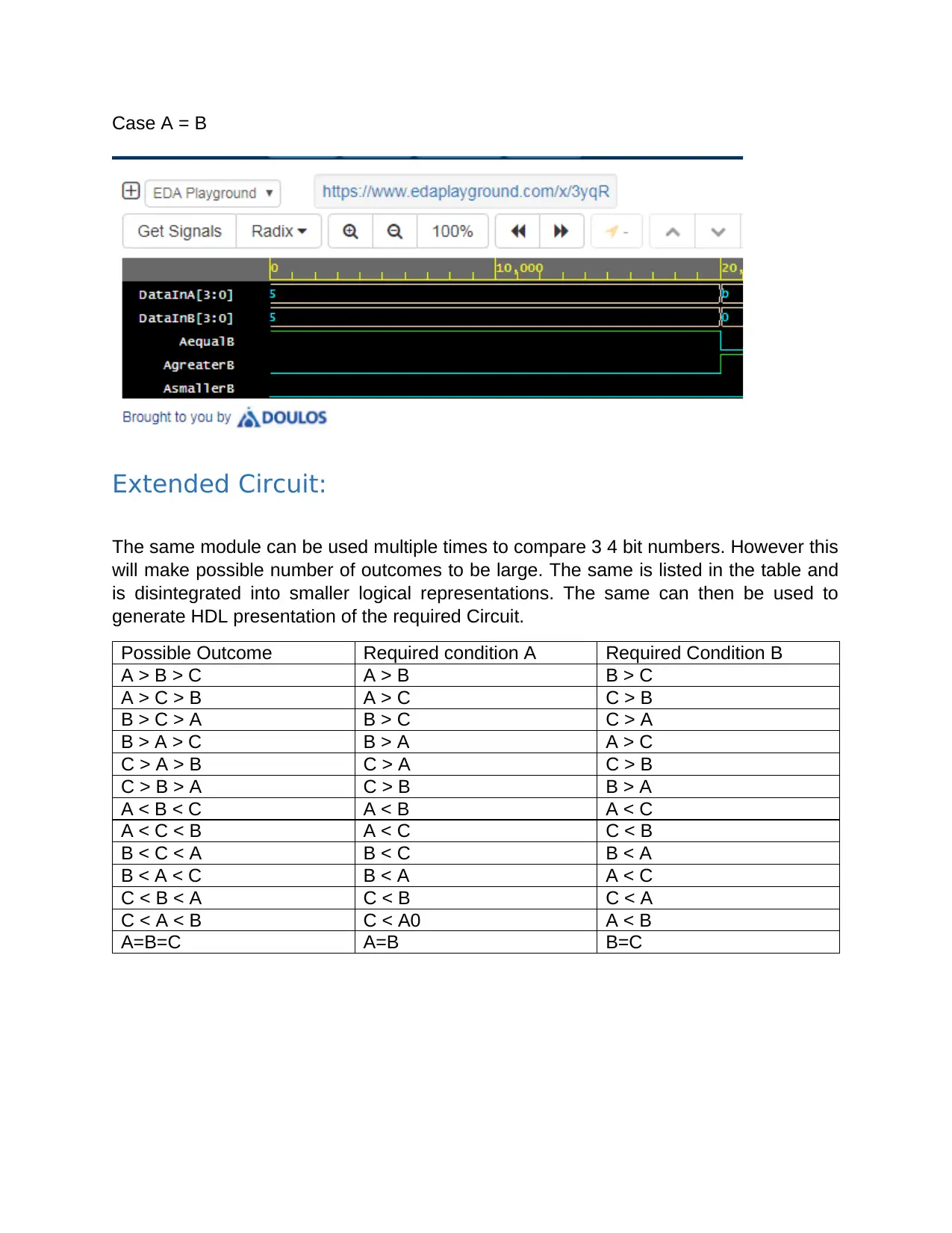
This assignment presents the design and implementation of two digital circuits. The first circuit controls an automated water sprinkler system based on inputs like time of day (morning/evening), rain, salinity, and humidity, using Boolean equations and a 7-segment display to indicate system status. The second circuit involves the design of a 4-bit comparator, implemented using both Boolean equations and VHDL code, along with a test bench for verification. The comparator design is then extended to compare three 4-bit numbers, with corresponding VHDL code and test bench. Simulation results are provided for both circuits, demonstrating their functionality. Gate costs are also calculated for the sprinkler system design. Desklib offers this and other solved assignments to aid students in their studies.

Assignment 1
Design procedure:
Identify inputs and outputs.
Find the relation between input conditions and output states. The same of first reflected
using a truth table.
EMPTY MORN EVEN RAIN SALINE DRY HUMID PUMP ALARM FLOW [2:0]
0 1 X 0 X X X 0 1 XXX
0 X 1 0 X X X 0 1 XXX
1 1 X 0 0 1 X 1 0 Very
High
111
1 1 X 0 1 0 11 1 0 High 110
1 1 X 0 1 0 10 1 0 Normal 011
1 1 X 0 1 0 01 1 0 Low 010
1 1 X 0 1 0 00 1 0 Very
Low
001
1 1 X 0 1 1 X 1 0 Normal 011
1 1 X 0 0 0 X 1 0 Low 010
1 X 1 0 0 1 X 1 0 Very
High
111
1 X 1 0 1 0 11 1 0 High 110
1 X 1 0 1 0 10 1 0 Normal 011
1 X 1 0 1 0 01 1 0 Low 010
1 X 1 0 1 0 00 1 0 Very
Low
001
1 X 1 0 1 1 X 1 0 Normal 011
1 X 1 0 0 0 X 1 0 Low 010
1 X X X 0 1 x 1 0 Very
High
111
Paraphrase This Document
Need a fresh take? Get an instant paraphrase of this document with our AI Paraphraser

Boolean Equations for Outputs:
Based on above set of inputs Output can be described as follows:
Pump = (EMPTY & MORN & ~RAIN) ||
(EMPTY & EVEN & ~RAIN) ||
(EMPTY & DRY & ~SALINE)
FLOW[2] = PUMP & (
(~SALINE & DRY) ||
(SALINE & ~DRY & HUMID[1] & HUMID[0])
)
Based on above set of inputs Output can be described as follows:
Pump = (EMPTY & MORN & ~RAIN) ||
(EMPTY & EVEN & ~RAIN) ||
(EMPTY & DRY & ~SALINE)
FLOW[2] = PUMP & (
(~SALINE & DRY) ||
(SALINE & ~DRY & HUMID[1] & HUMID[0])
)

FLOW[1] = PUMP & ~(SALINE & ~DRY & HUMID[1] & HUMID[0] )
FLOW[0] = PUMP & ( DRY || (SALINE & ~HUMID[0]) )
ALARM = ~EMPTY & ~RAIN & (MORN || EVEN)
LED Segment Truth Table
PUMP ALARM A B C D E F G
0 0 1 1 1 1 1
0 1 1 1 1 1 1 1
1 0 1 1 1 1 1
1 1 1 1 1 1 1 1
FLOW[0] = PUMP & ( DRY || (SALINE & ~HUMID[0]) )
ALARM = ~EMPTY & ~RAIN & (MORN || EVEN)
LED Segment Truth Table
PUMP ALARM A B C D E F G
0 0 1 1 1 1 1
0 1 1 1 1 1 1 1
1 0 1 1 1 1 1
1 1 1 1 1 1 1 1
⊘ This is a preview!⊘
Do you want full access?
Subscribe today to unlock all pages.

Trusted by 1+ million students worldwide

SEVEN[A] = 1
SEVEN[B] = PUMP || ALARM
SEVEN[C] = ALARM || ~PUMP
SEVEN[D] = ~PUMP & ~ALARM
SEVEN[E] = PUMP || ALARM
SEVEN[F] = 1
SEVEN[G] = 1
Choice of technology
The simple 74LS series IC can be used to realize the circuit. The series operates at 5V
without any major current consumption and is easily available in DIP packages for
bread board based circuit testing.
Implementation
The circuit is implemented using basic gates and a seven segment display unit.
Paraphrase This Document
Need a fresh take? Get an instant paraphrase of this document with our AI Paraphraser

Simulation results:
The first condition is when EMPTY is asserted and MORN or EVEN conditions are true,
RAIN is not present. This is expected to cause an ALARM to be asserted and LED
should show A symbol.
The second condition is when EMPTY is not asserted and MORN or EVEN conditions
are true, RAIN is not present.
The first condition is when EMPTY is asserted and MORN or EVEN conditions are true,
RAIN is not present. This is expected to cause an ALARM to be asserted and LED
should show A symbol.
The second condition is when EMPTY is not asserted and MORN or EVEN conditions
are true, RAIN is not present.

The third condition is when pumping is stopped and pump is in normal condition without
alarm. This is when RAIN is asserted or when MORN, EVEN signals are not present
Gate Cost
The list here summarizes Gate cost based on 2 input Gates. The circuit has used 3 and
4 input gates for simulation purpose.
NOT Gate :- 8
OR Gate :- 10
AND Gate:- 23
alarm. This is when RAIN is asserted or when MORN, EVEN signals are not present
Gate Cost
The list here summarizes Gate cost based on 2 input Gates. The circuit has used 3 and
4 input gates for simulation purpose.
NOT Gate :- 8
OR Gate :- 10
AND Gate:- 23
⊘ This is a preview!⊘
Do you want full access?
Subscribe today to unlock all pages.

Trusted by 1+ million students worldwide

Assignment 2
Design procedure:
The comparator circuit starts by comparing the MSB of the inputs and calculates output.
If MSB are same then next lower bit is compared until a difference is found. Depending
upon which bit is 1, the result is determined. In case all bits are same, numbers are
considered equal. The same is represented in this Truth Table for a 4 bit Comparator:
A[3]:B[3] A[2]:B[2] A[1]:B[1] A[0]:B[0] A>B A=B A<B
A3 > B3 X X X 1 0 0
A3 < B3 X X X 0 0 1
A3=B3 A2>B2 X X 1 0 0
A3=B3 A2 < B2 X X 0 0 1
A3=B3 A2 = B2 A1>B1 X 1 0 0
A3=B3 A2 = B2 A1 < B1 X 0 0 1
A3=B3 A2 = B2 A1=B1 A0 > B0 1 0 0
A3=B3 A2 = B2 A1=B1 A0 < B0 0 0 1
A3=B3 A2 = B2 A1=B1 A0 = B0 0 1 0
Boolean Equations:
A > B :- A3 & ~B3 ||
A3 & B3 & A2 & ~ B2 ||
A3 & B3 & A2 & B2 & A1 & ~B1 ||
A3 & B3 & A2 & B2 & A1 & B1 & A0 & ~B0
A = B :- (A3 ʘ B3) & (A2 ʘ B2) & (A1 ʘ B1) & (A0 ʘ B0)
A < B :- ~(A=B) & ~(A>B)
Paraphrase This Document
Need a fresh take? Get an instant paraphrase of this document with our AI Paraphraser

Circuit diagram:
Though it is possible to write a Boolean equation in this case but it becomes error prone
and tedious to do such calculations with 8 bit inputs. It is preferred to use HDL to realize
such circuits and perform verification of its functionality using HDL test bench
methodologies.
Though it is possible to write a Boolean equation in this case but it becomes error prone
and tedious to do such calculations with 8 bit inputs. It is preferred to use HDL to realize
such circuits and perform verification of its functionality using HDL test bench
methodologies.

HDL Code:
4 Bit Comparator:
LIBRARY IEEE;
USE IEEE.STD_LOGIC_1164.ALL;
USE IEEE.NUMERIC_STD.ALL; --IEEE.STD_LOGIC_ARITH.ALL;
-- USE IEEE.STD_LOGIC_UNSIGNED.ALL;
ENTITY COMPARATOR4BIT IS PORT (
DATAINA,DATAINB : IN STD_LOGIC_VECTOR(3 DOWNTO 0);
AGREATERB, AEQUALB, ASMALLERB : OUT STD_LOGIC
);
END COMPARATOR4BIT ;
ARCHITECTURE IMPL OF COMPARATOR4BIT IS
BEGIN
AGREATERB <= '1' WHEN (DATAINA > DATAINB) ELSE '0';
AEQUALB <= '1' WHEN (DATAINA = DATAINB) ELSE '0';
ASMALLERB <= '1' WHEN (DATAINA < DATAINB) ELSE '0';
END IMPL;
⊘ This is a preview!⊘
Do you want full access?
Subscribe today to unlock all pages.

Trusted by 1+ million students worldwide

Test Bench for 4 Bit Comparator:
-- CODE YOUR TESTBENCH HERE
LIBRARY IEEE;
USE IEEE.STD_LOGIC_1164.ALL;
USE IEEE.NUMERIC_STD.ALL;
USE STD.ENV.STOP;
ENTITY COMPARATOR4BIT_TB IS
END ENTITY COMPARATOR4BIT_TB ;
ARCHITECTURE IMPL OF COMPARATOR4BIT_TB IS
COMPONENT COMPARATOR4BIT IS PORT (
DATAINA,DATAINB : IN STD_LOGIC_VECTOR(3 DOWNTO 0);
AGREATERB, AEQUALB, ASMALLERB : OUT STD_LOGIC);
END COMPONENT COMPARATOR4BIT;
SIGNAL DATAINA,DATAINB : STD_LOGIC_VECTOR(3 DOWNTO 0);
SIGNAL AGREATERB, AEQUALB, ASMALLERB : STD_LOGIC;
BEGIN
DUT: COMPARATOR4BIT PORT MAP (DATAINA,DATAINB,AGREATERB,AEQUALB,ASMALLERB);
--END
STIMULUS : PROCESS
BEGIN
DATAINA <= "0000";
DATAINB <= "1100";
WAIT FOR 20 NS;
DATAINA <= "1110";
DATAINB <= "1100";
WAIT FOR 20 NS;
DATAINA <= "0101";
DATAINB <= "0101";
WAIT FOR 20 NS;
DATAINA <= "1011";
DATAINB <= "0000";
WAIT FOR 20 NS;
DATAINA <= "1110";
DATAINB <= "1100";
WAIT FOR 20 NS;
STOP(2);
END PROCESS STIMULUS;
END IMPL;
Paraphrase This Document
Need a fresh take? Get an instant paraphrase of this document with our AI Paraphraser

Simulation Results:
Case when A < B
Case when A > B
Case when A < B
Case when A > B

Case A = B
Extended Circuit:
The same module can be used multiple times to compare 3 4 bit numbers. However this
will make possible number of outcomes to be large. The same is listed in the table and
is disintegrated into smaller logical representations. The same can then be used to
generate HDL presentation of the required Circuit.
Possible Outcome Required condition A Required Condition B
A > B > C A > B B > C
A > C > B A > C C > B
B > C > A B > C C > A
B > A > C B > A A > C
C > A > B C > A C > B
C > B > A C > B B > A
A < B < C A < B A < C
A < C < B A < C C < B
B < C < A B < C B < A
B < A < C B < A A < C
C < B < A C < B C < A
C < A < B C < A0 A < B
A=B=C A=B B=C
⊘ This is a preview!⊘
Do you want full access?
Subscribe today to unlock all pages.

Trusted by 1+ million students worldwide
1 out of 17
Your All-in-One AI-Powered Toolkit for Academic Success.
+13062052269
info@desklib.com
Available 24*7 on WhatsApp / Email
Unlock your academic potential
Copyright © 2020–2025 A2Z Services. All Rights Reserved. Developed and managed by ZUCOL.