Electric Car Design Project: Detailed Component Design and Assembly
VerifiedAdded on 2023/01/11
|10
|2007
|23
Project
AI Summary
This project details the design of an electric car, breaking down its components and their respective functions. The main body, front body, and tail body are designed with considerations for dimensions and structural integrity, and the design process is outlined using CAD software. Components like the lithium-ion battery, wheels, tires, and socket inserts are also designed and their roles in the car's operation are explained. The DC motor and gear mechanism are discussed, highlighting their importance in converting electrical energy into mechanical energy to drive the car's wheels. The design processes for each component include sketches, extrusion, and other CAD features, providing a comprehensive understanding of the electric car's design and assembly. References from various engineering and design resources are also included.
Electric Car
There are main parts of the Car given below:
Main body, Front body, Tail Body, Wheel, Tire for wheel, Socket, Lithium ion Battery
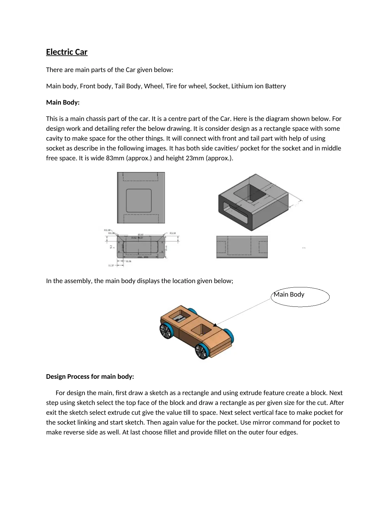
Main Body:
This is a main chassis part of the car. It is a centre part of the Car. Here is the diagram shown below. For
design work and detailing refer the below drawing. It is consider design as a rectangle space with some
cavity to make space for the other things. It will connect with front and tail part with help of using
socket as describe in the following images. It has both side cavities/ pocket for the socket and in middle
free space. It is wide 83mm (approx.) and height 23mm (approx.).
In the assembly, the main body displays the location given below;
Design Process for main body:
For design the main, first draw a sketch as a rectangle and using extrude feature create a block. Next
step using sketch select the top face of the block and draw a rectangle as per given size for the cut. After
exit the sketch select extrude cut give the value till to space. Next select vertical face to make pocket for
the socket linking and start sketch. Then again value for the pocket. Use mirror command for pocket to
make reverse side as well. At last choose fillet and provide fillet on the outer four edges.
Main Body
There are main parts of the Car given below:
Main body, Front body, Tail Body, Wheel, Tire for wheel, Socket, Lithium ion Battery
Main Body:
This is a main chassis part of the car. It is a centre part of the Car. Here is the diagram shown below. For
design work and detailing refer the below drawing. It is consider design as a rectangle space with some
cavity to make space for the other things. It will connect with front and tail part with help of using
socket as describe in the following images. It has both side cavities/ pocket for the socket and in middle
free space. It is wide 83mm (approx.) and height 23mm (approx.).
In the assembly, the main body displays the location given below;
Design Process for main body:
For design the main, first draw a sketch as a rectangle and using extrude feature create a block. Next
step using sketch select the top face of the block and draw a rectangle as per given size for the cut. After
exit the sketch select extrude cut give the value till to space. Next select vertical face to make pocket for
the socket linking and start sketch. Then again value for the pocket. Use mirror command for pocket to
make reverse side as well. At last choose fillet and provide fillet on the outer four edges.
Main Body
Paraphrase This Document
Need a fresh take? Get an instant paraphrase of this document with our AI Paraphraser
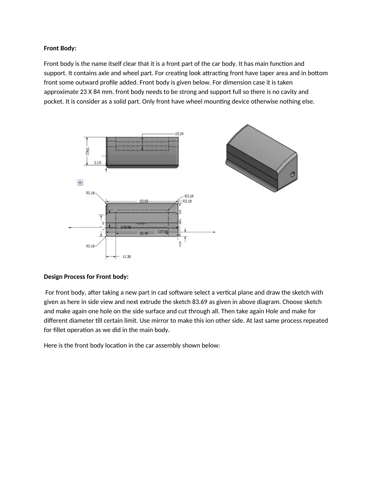
Front Body:
Front body is the name itself clear that it is a front part of the car body. It has main function and
support. It contains axle and wheel part. For creating look attracting front have taper area and in bottom
front some outward profile added. Front body is given below. For dimension case it is taken
approximate 23 X 84 mm. front body needs to be strong and support full so there is no cavity and
pocket. It is consider as a solid part. Only front have wheel mounting device otherwise nothing else.
Design Process for Front body:
For front body, after taking a new part in cad software select a vertical plane and draw the sketch with
given as here in side view and next extrude the sketch 83.69 as given in above diagram. Choose sketch
and make again one hole on the side surface and cut through all. Then take again Hole and make for
different diameter till certain limit. Use mirror to make this ion other side. At last same process repeated
for fillet operation as we did in the main body.
Here is the front body location in the car assembly shown below:
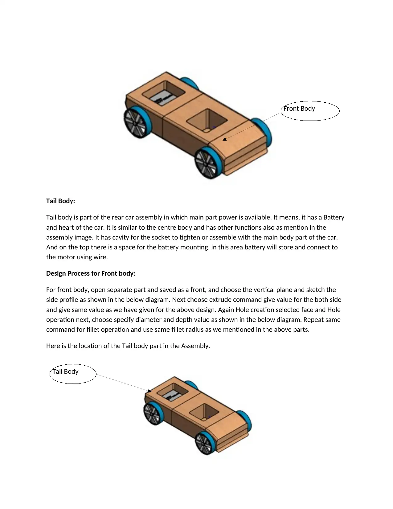
Tail Body:
Tail body is part of the rear car assembly in which main part power is available. It means, it has a Battery
and heart of the car. It is similar to the centre body and has other functions also as mention in the
assembly image. It has cavity for the socket to tighten or assemble with the main body part of the car.
And on the top there is a space for the battery mounting, in this area battery will store and connect to
the motor using wire.
Design Process for Front body:
For front body, open separate part and saved as a front, and choose the vertical plane and sketch the
side profile as shown in the below diagram. Next choose extrude command give value for the both side
and give same value as we have given for the above design. Again Hole creation selected face and Hole
operation next, choose specify diameter and depth value as shown in the below diagram. Repeat same
command for fillet operation and use same fillet radius as we mentioned in the above parts.
Here is the location of the Tail body part in the Assembly.
Front Body
Tail Body
⊘ This is a preview!⊘
Do you want full access?
Subscribe today to unlock all pages.
Trusted by 1+ million students worldwide
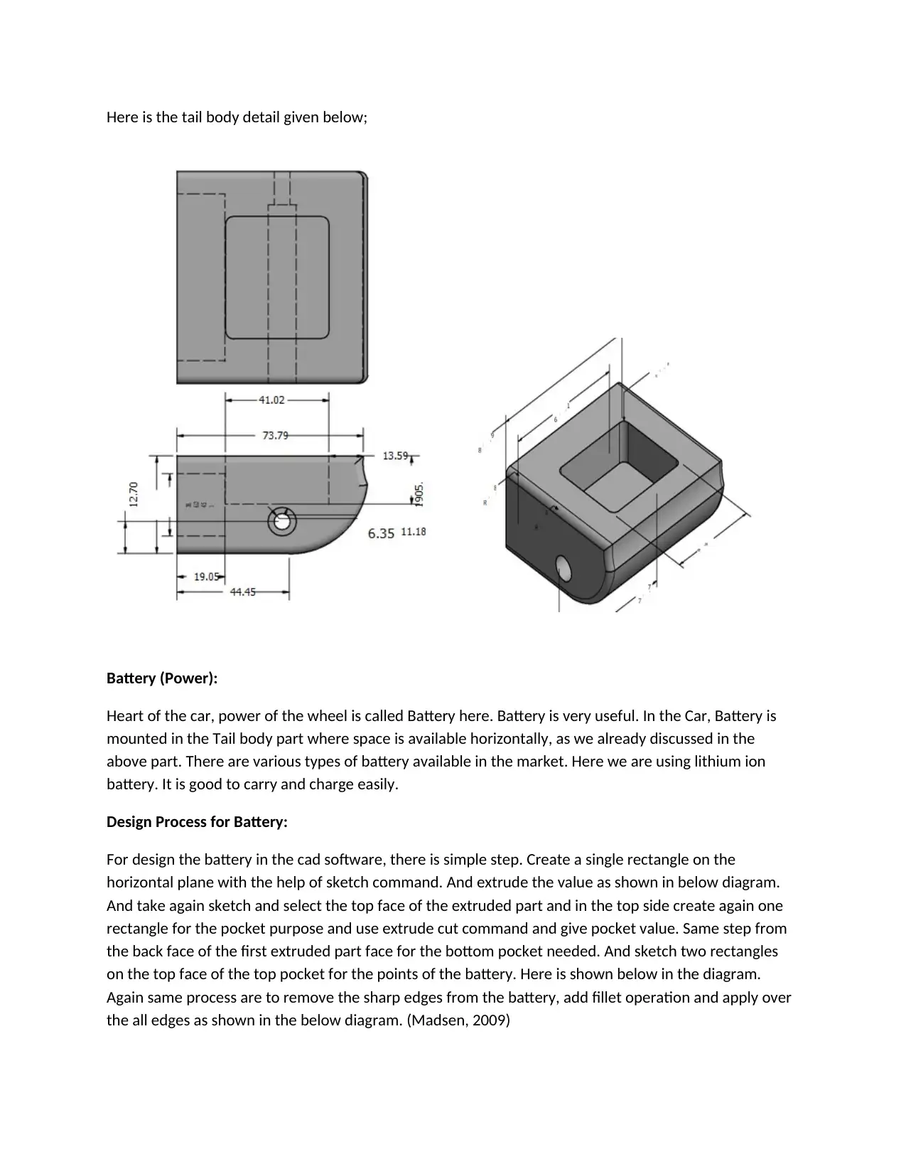
Here is the tail body detail given below;
Battery (Power):
Heart of the car, power of the wheel is called Battery here. Battery is very useful. In the Car, Battery is
mounted in the Tail body part where space is available horizontally, as we already discussed in the
above part. There are various types of battery available in the market. Here we are using lithium ion
battery. It is good to carry and charge easily.
Design Process for Battery:
For design the battery in the cad software, there is simple step. Create a single rectangle on the
horizontal plane with the help of sketch command. And extrude the value as shown in below diagram.
And take again sketch and select the top face of the extruded part and in the top side create again one
rectangle for the pocket purpose and use extrude cut command and give pocket value. Same step from
the back face of the first extruded part face for the bottom pocket needed. And sketch two rectangles
on the top face of the top pocket for the points of the battery. Here is shown below in the diagram.
Again same process are to remove the sharp edges from the battery, add fillet operation and apply over
the all edges as shown in the below diagram. (Madsen, 2009)
Paraphrase This Document
Need a fresh take? Get an instant paraphrase of this document with our AI Paraphraser
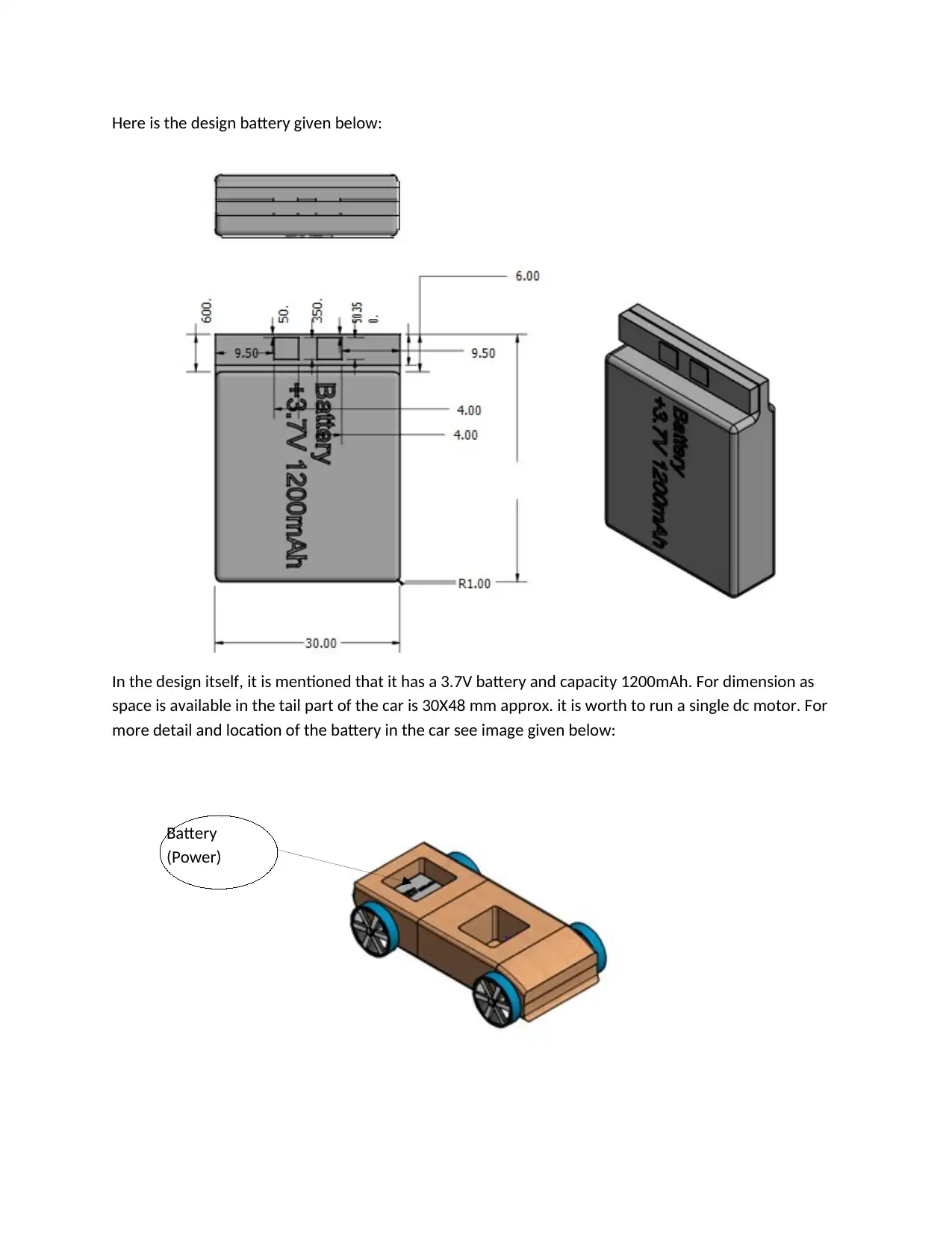
Here is the design battery given below:
In the design itself, it is mentioned that it has a 3.7V battery and capacity 1200mAh. For dimension as
space is available in the tail part of the car is 30X48 mm approx. it is worth to run a single dc motor. For
more detail and location of the battery in the car see image given below:
Battery
(Power)
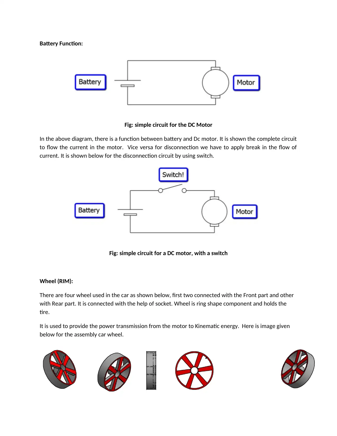
Battery Function:
Fig: simple circuit for the DC Motor
In the above diagram, there is a function between battery and Dc motor. It is shown the complete circuit
to flow the current in the motor. Vice versa for disconnection we have to apply break in the flow of
current. It is shown below for the disconnection circuit by using switch.
Fig: simple circuit for a DC motor, with a switch
Wheel (RIM):
There are four wheel used in the car as shown below, first two connected with the Front part and other
with Rear part. It is connected with the help of socket. Wheel is ring shape component and holds the
tire.
It is used to provide the power transmission from the motor to Kinematic energy. Here is image given
below for the assembly car wheel.
⊘ This is a preview!⊘
Do you want full access?
Subscribe today to unlock all pages.
Trusted by 1+ million students worldwide
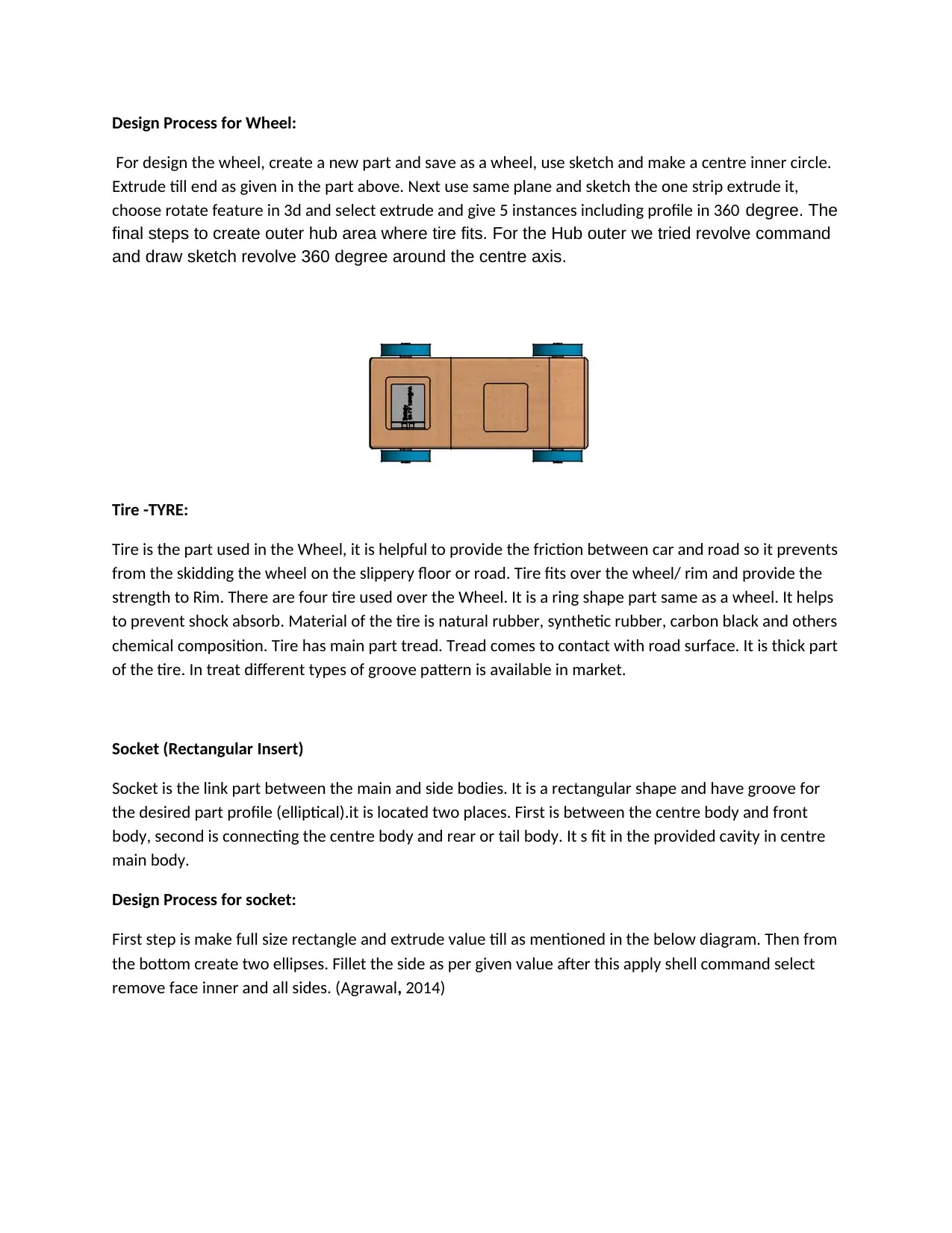
Design Process for Wheel:
For design the wheel, create a new part and save as a wheel, use sketch and make a centre inner circle.
Extrude till end as given in the part above. Next use same plane and sketch the one strip extrude it,
choose rotate feature in 3d and select extrude and give 5 instances including profile in 360 degree. The
final steps to create outer hub area where tire fits. For the Hub outer we tried revolve command
and draw sketch revolve 360 degree around the centre axis.
Tire -TYRE:
Tire is the part used in the Wheel, it is helpful to provide the friction between car and road so it prevents
from the skidding the wheel on the slippery floor or road. Tire fits over the wheel/ rim and provide the
strength to Rim. There are four tire used over the Wheel. It is a ring shape part same as a wheel. It helps
to prevent shock absorb. Material of the tire is natural rubber, synthetic rubber, carbon black and others
chemical composition. Tire has main part tread. Tread comes to contact with road surface. It is thick part
of the tire. In treat different types of groove pattern is available in market.
Socket (Rectangular Insert)
Socket is the link part between the main and side bodies. It is a rectangular shape and have groove for
the desired part profile (elliptical).it is located two places. First is between the centre body and front
body, second is connecting the centre body and rear or tail body. It s fit in the provided cavity in centre
main body.
Design Process for socket:
First step is make full size rectangle and extrude value till as mentioned in the below diagram. Then from
the bottom create two ellipses. Fillet the side as per given value after this apply shell command select
remove face inner and all sides. (Agrawal, 2014)
Paraphrase This Document
Need a fresh take? Get an instant paraphrase of this document with our AI Paraphraser
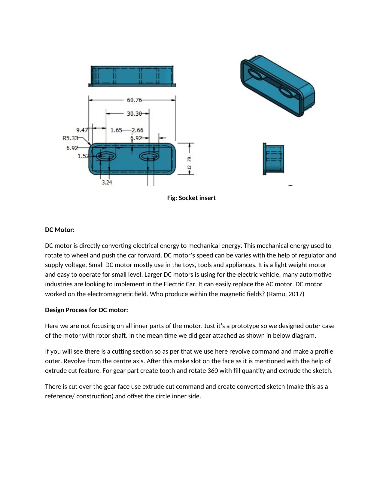
Fig: Socket insert
DC Motor:
DC motor is directly converting electrical energy to mechanical energy. This mechanical energy used to
rotate to wheel and push the car forward. DC motor’s speed can be varies with the help of regulator and
supply voltage. Small DC motor mostly use in the toys, tools and appliances. It is a light weight motor
and easy to operate for small level. Larger DC motors is using for the electric vehicle, many automotive
industries are looking to implement in the Electric Car. It can easily replace the AC motor. DC motor
worked on the electromagnetic field. Who produce within the magnetic fields? (Ramu, 2017)
Design Process for DC motor:
Here we are not focusing on all inner parts of the motor. Just it’s a prototype so we designed outer case
of the motor with rotor shaft. In the mean time we did gear attached as shown in below diagram.
If you will see there is a cutting section so as per that we use here revolve command and make a profile
outer. Revolve from the centre axis. After this make slot on the face as it is mentioned with the help of
extrude cut feature. For gear part create tooth and rotate 360 with fill quantity and extrude the sketch.
There is cut over the gear face use extrude cut command and create converted sketch (make this as a
reference/ construction) and offset the circle inner side.
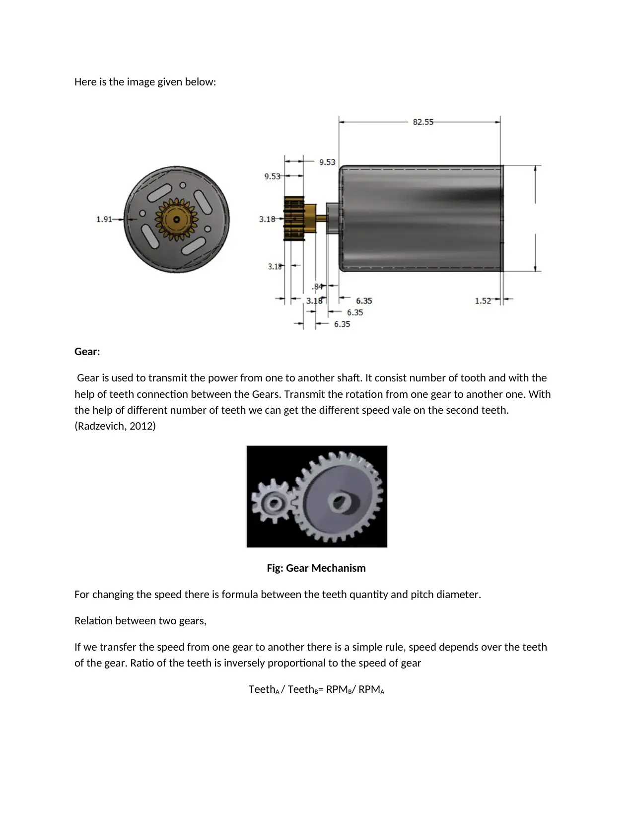
Here is the image given below:
Gear:
Gear is used to transmit the power from one to another shaft. It consist number of tooth and with the
help of teeth connection between the Gears. Transmit the rotation from one gear to another one. With
the help of different number of teeth we can get the different speed vale on the second teeth.
(Radzevich, 2012)
Fig: Gear Mechanism
For changing the speed there is formula between the teeth quantity and pitch diameter.
Relation between two gears,
If we transfer the speed from one gear to another there is a simple rule, speed depends over the teeth
of the gear. Ratio of the teeth is inversely proportional to the speed of gear
TeethA / TeethB= RPMB/ RPMA
⊘ This is a preview!⊘
Do you want full access?
Subscribe today to unlock all pages.
Trusted by 1+ million students worldwide
References:
Radzevich, S. (2012) Dudley's Handbook of Practical Gear Design and Manufacture, CRC Press
Madsen, A. (2009) Engineering Drawing and Design, Delmar Cengage Learning
Agrawal, B. (2014) Engineering Drawing, McGraw-Hill Education
Ramu, K. (2017) Permanent Magnet Synchronous and Brushless DC Motor Drives, CRC Press
1 out of 10
Your All-in-One AI-Powered Toolkit for Academic Success.
+13062052269
info@desklib.com
Available 24*7 on WhatsApp / Email
![[object Object]](/_next/static/media/star-bottom.7253800d.svg)
Unlock your academic potential
Copyright © 2020–2026 A2Z Services. All Rights Reserved. Developed and managed by ZUCOL.