Modeling Electric Toothbrush State Transitions with Simulink
VerifiedAdded on 2023/01/23
|14
|1724
|33
Project
AI Summary
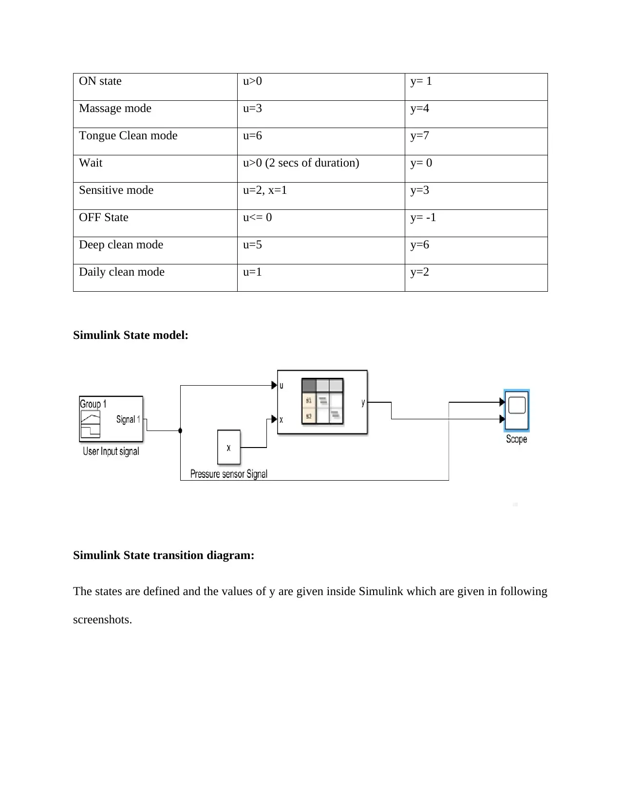
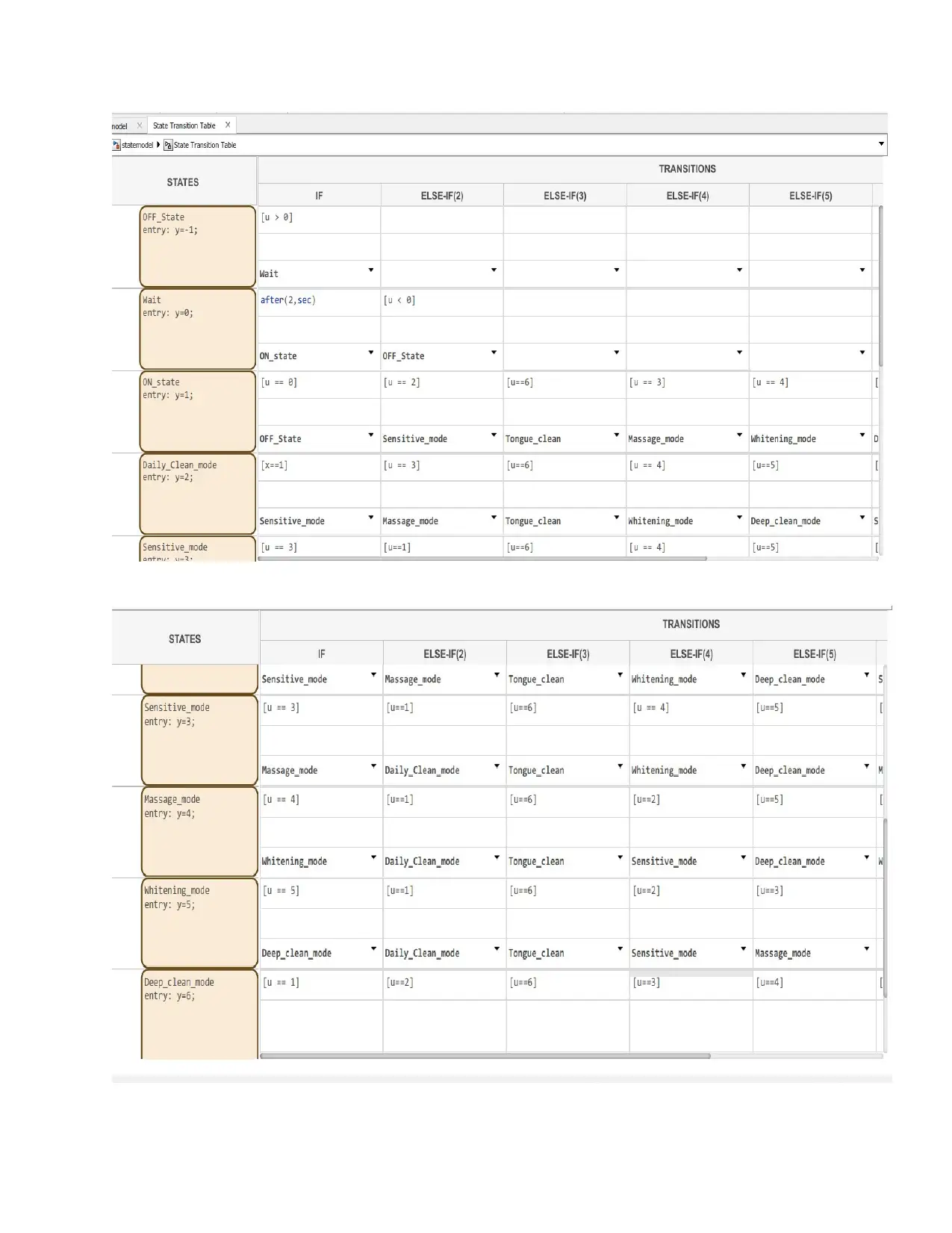
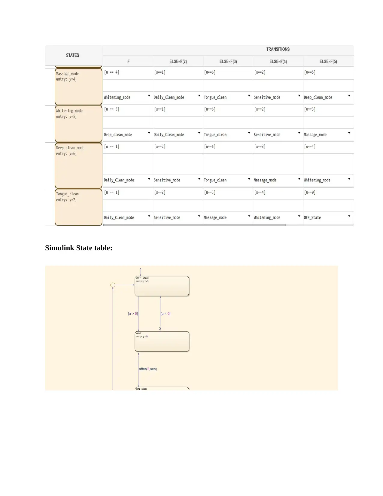
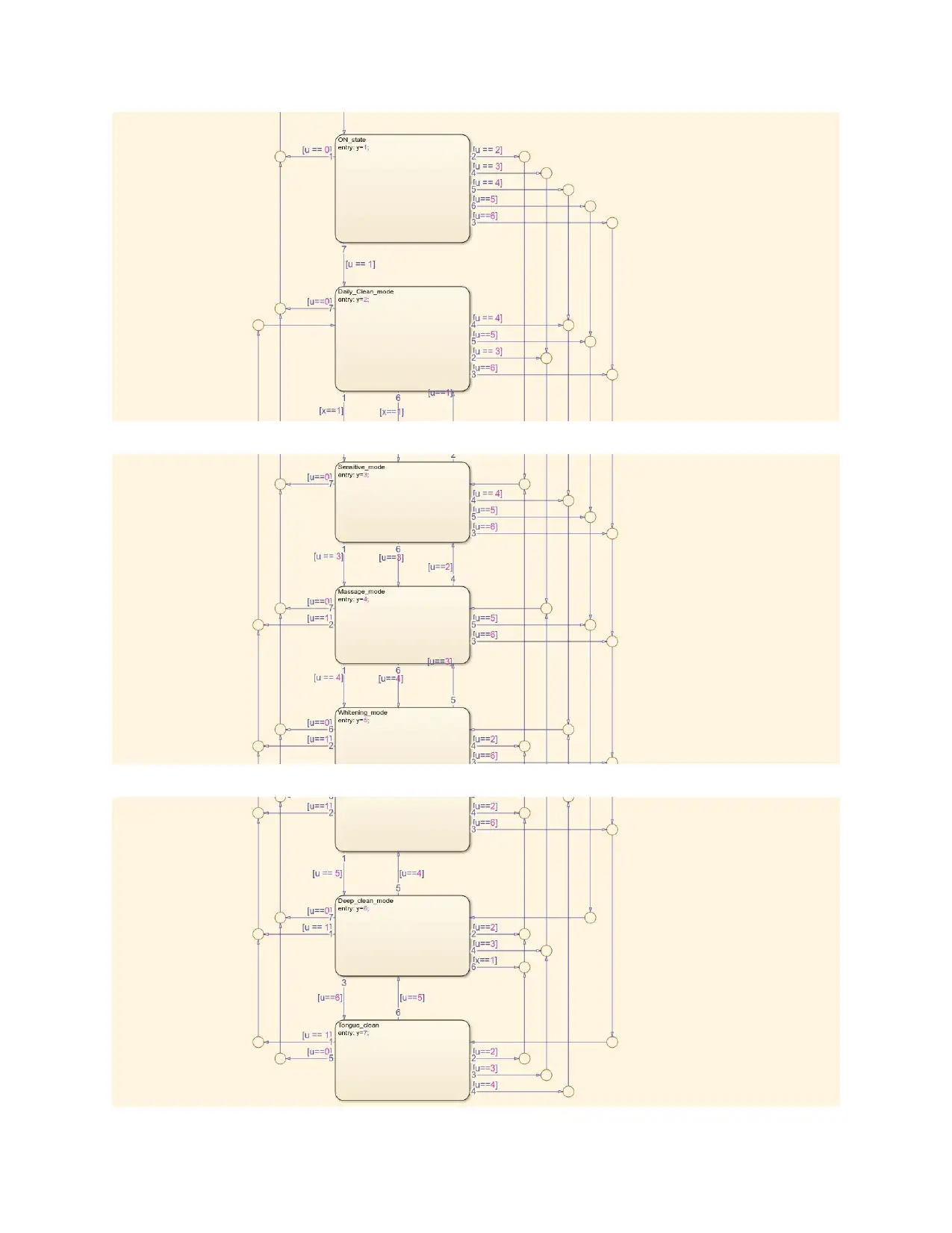
This assignment presents a state transition diagram for an Oral B electric toothbrush, modeling its various brushing modes (daily clean, deep clean, etc.) as states. The project utilizes MATLAB/Simulink to create a visual representation of these states and their transitions, triggered by user inputs and pressure sensor data. The student defines states, transition signals, and uses a Simulink state transition matrix to simulate the toothbrush's behavior, including the impact of over-pressure conditions. The testing procedure involves random user inputs and pressure signals, demonstrating how the system transitions between states based on these inputs. The assignment successfully models the logical operations of the toothbrush, showcasing the effectiveness of state transition diagrams in analyzing system behavior and highlighting the potential for expanding the model to include additional features like timer modes. The student provides detailed explanations of the Simulink model, testing procedures, and conclusions.

Name of the Student
Assignment 1
State transition diagram
Name of the Instructor
Date
Assignment 1
State transition diagram
Name of the Instructor
Date
Paraphrase This Document
Need a fresh take? Get an instant paraphrase of this document with our AI Paraphraser

Introduction:
State transition diagram is a diagrammatic representation of the states of machine
between which transitions occurs corresponding to specific conditions or inputs to the machine.
The states of machine are the stages in which the machine is operated. In this particular
experiment the state transition diagram is developed for the oral B Braun electric toothbrush. The
major functionalities (or typically the different brushing modes) of the electric toothbrush is
assumed as states of the machine and the transition between the states occur due to user input
signals which is converted into certain specific values functional signal by the SmartGuide
system (Yang et al. 2016). Now, for creating the state transition diagram MATLAB/Simulink is
used due to its ability to create attractive visualization of graphs and ability to do enormous
computations within small amount of time. In addition to this the Simulink model is created in
MATLAB as state transition matrix as an inbuilt model is available as a Simulink block (Rumpe
et al. 2015). Inside the Simulink block the different states of the toothbrush is defined and their
transition signals specified by hypothetical values. The different functionalities of the toothbrush
is defined below.
Various Functionality of the toothbrush 5000 & SmartGuide Interface:
The mostly important functionalities of the oral B Braun electric toothbrush is given below.
The toothbrush’s power supply is the rechargeable battery which keeps the charge for a
long time of typically 1-2 days with normal brushing frequency of 2 times in a week. The
charging of the toothbrush is very simple and easy to use as it only requires to plug in the
plug of the toothbrush in any 3-pin outlet.

The two timer modes that are offered inside oral B Braun electric toothbrush are the
professional timer mode and 2-minuite timer mode. In the professional timer mode each
of the brushing mode is operated for a time interval of 30 seconds except for the daily
clean and deep clean mode which are operated for about 45 seconds in default. The user
can change the time interval for each brushing modes in professional mode. Additionally,
a green light flashes with a shuttering sound after each mode is over. This is common for
2-minute timer mode also. Instead, the user does not have the option to change the
timings of each of the mode.
The live brushing experience can be viewed from any machine (mac / linux or windows)
by the user as the live feedback while brushing can be sent to the machine by the
Bluetooth pairing of the toothbrush with machine. However, the SmartGuide software
need to be installed in the viewing machine to oversee the live feedback.
The brushing modes which are modelled as states of machine are daily clean mode, deep
clean mode, whitening mode, massage mode, tongue cleaning mode and sensitive mode
respectively.
Inside the toothbrush there is a pressure sensor built-in in the toothbrush. The function of
the pressure sensor is to obtain the pressure applied by the user at the time of brushing
and then the mechanical pressure is converted to electric signals by piezoelectric
transducers and SmartGuide software increases magnitude of the signal according to the
applied pressure (Zou et al. 2015). Now, when the pressure is over the specified limit
then the toothbrush is changed to sensitive mode when the operating mode is daily clean
or deep clean mode. The over-pressure is displayed in the SmartScreen and indicated in
the toothbrush with warning sound and red light.
⊘ This is a preview!⊘
Do you want full access?
Subscribe today to unlock all pages.

Trusted by 1+ million students worldwide

Description of the state transition diagram:
The primary delay given to toothbrush for switching from OFF state to ON state in 2
seconds and this function is added to electrically activate each and every components inside the
electric toothbrush. When the toothbrush goes to ON state then the user can selectively take any
state or can choose any timer mode.
Now, the primary brushing modes of the machine are the states of the machine as considered in
this assignment. Additionally, the ON, OFF and Wait time are also considered as extra states of
the machine. Each of the states are represented as a signal y in MATLAB for testing the system.
Also, the input signals converted into specified valued signals by SmartGuide software and this
is represented using the signal u with specific values responsible for state transition (Tanaka et
al. 2017). There is another signal which is the pressure signal x which assumes the value 1 when
the pressure is over the specified limit in daily clean mode or deep clean mode and assumes the
value 0 when the pressure is low (Bartocci et al. 2018). All values of the signal are assumed to be
discrete values. If the power supply from the rechargeable battery fall below minimum excitation
limit for staying in toothbrush circuit in excited stage, the toothbrush switches to OFF state and
this is represented here as value of user input signal u<=0. The description of states and their
transition conditions are represented in following table.
State Name State transition signal Signal indicating state of
the machine
Whitening mode u=4 y=5
Paraphrase This Document
Need a fresh take? Get an instant paraphrase of this document with our AI Paraphraser

ON state u>0 y= 1
Massage mode u=3 y=4
Tongue Clean mode u=6 y=7
Wait u>0 (2 secs of duration) y= 0
Sensitive mode u=2, x=1 y=3
OFF State u<= 0 y= -1
Deep clean mode u=5 y=6
Daily clean mode u=1 y=2
Simulink State model:
Simulink State transition diagram:
The states are defined and the values of y are given inside Simulink which are given in following
screenshots.

⊘ This is a preview!⊘
Do you want full access?
Subscribe today to unlock all pages.

Trusted by 1+ million students worldwide

Simulink State table:
Paraphrase This Document
Need a fresh take? Get an instant paraphrase of this document with our AI Paraphraser


Testing procedure:
Now, the most important part of the assignment is done where the state transition matrix
in Simulink is initiated with randomized (extracted from uniform probability distribution) user
input signal u within the specified range as given in the state table. The pressure applied by the
user is random and thus the pressure signal is modelled using the random integer taken from
Gaussian distribution in the range [0,1]. The testing of the machine are given below.
Signal x generation:
x=randi([0,1],1)
x =
1
Input signal u=6 and pressure signal x = 1:
The pressure applied by the user is over the limit and use chooses the tongue cleaning mode for
all the time.
⊘ This is a preview!⊘
Do you want full access?
Subscribe today to unlock all pages.

Trusted by 1+ million students worldwide

Figure 1
From the above diagram it is clearly seen that the ON state transition from the OFF state is
obtained after slightly more than 2 seconds. This extra delay in milliseconds is constant as
specified in MATLAB and known as the delay of state transition. After getting in ON state the
system goes directly into y=7 or the tongue cleaning mode.
x=randi([0,1],1)
x =
1
Input signal u=5 and pressure signal x = 1:
Now, the user chosen for the deep clean mode and the applied pressure is always greater than the
limit.
Paraphrase This Document
Need a fresh take? Get an instant paraphrase of this document with our AI Paraphraser

Figure 2
Now, an interesting graph can be observed. In this graph an oscillatory behavior between the
states y=6 and y=3 is observed. This happen because as per the state table condition when the
pressure is over the limit then the toothbrush automatically moves to sensitive mode when it is
operating in deep clean mode. However, as the user constantly opts for the deep clean mode with
pressure signal high the system every time switches to sensitive mode and the oscillatory
behavior is produced.

Conclusion:
Conclusively it can be said that the objectives of the assignment is successfully implemented as
the machine states are appropriately assumed and the state transitions occurred based on the
different transition conditions. Additionally, by employing more stages more of the states like
the professional and 2 minute timer modes, a bigger state transition diagram can be developed
and can be tested with different input signals. The actual state transitions within the toothbrush is
different and depends on the internal circuitry of the toothbrush, however, the logical operation
of states are same as provided in this assignment.
⊘ This is a preview!⊘
Do you want full access?
Subscribe today to unlock all pages.

Trusted by 1+ million students worldwide
1 out of 14
Related Documents

Your All-in-One AI-Powered Toolkit for Academic Success.
+13062052269
info@desklib.com
Available 24*7 on WhatsApp / Email
Unlock your academic potential
Copyright © 2020–2025 A2Z Services. All Rights Reserved. Developed and managed by ZUCOL.