Static Engineering System Task 1: Electrical Circuit and Beam Analysis

Verified

Added on  2019/12/18

|32
|3416
|392
Homework Assignment
AI Summary
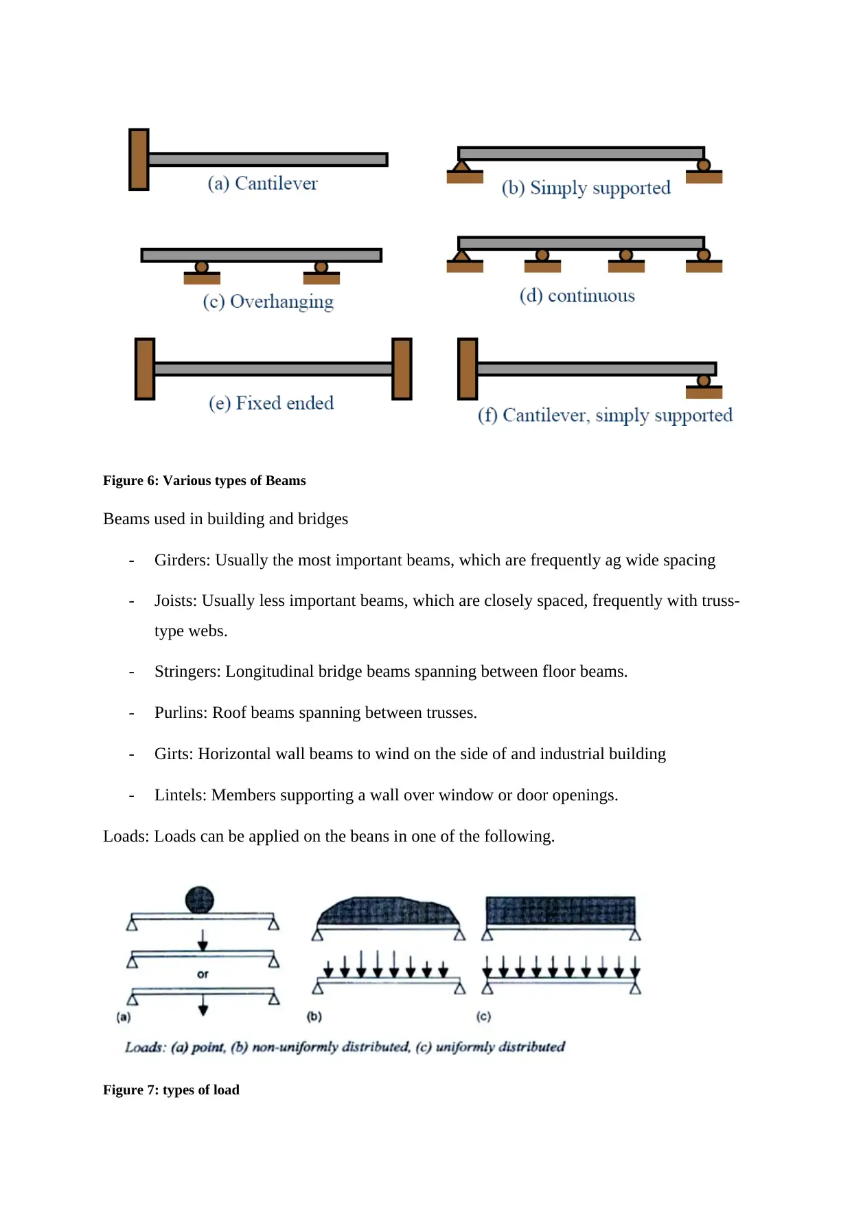
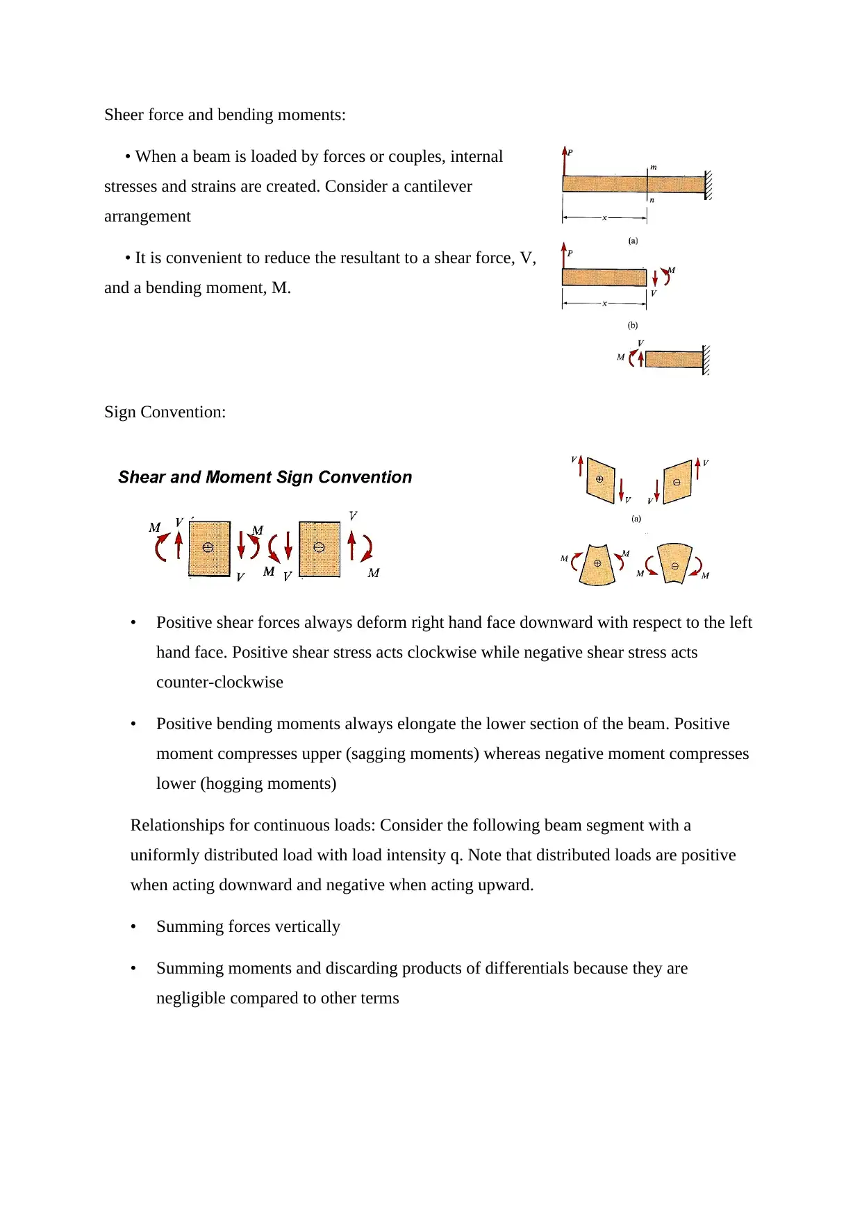
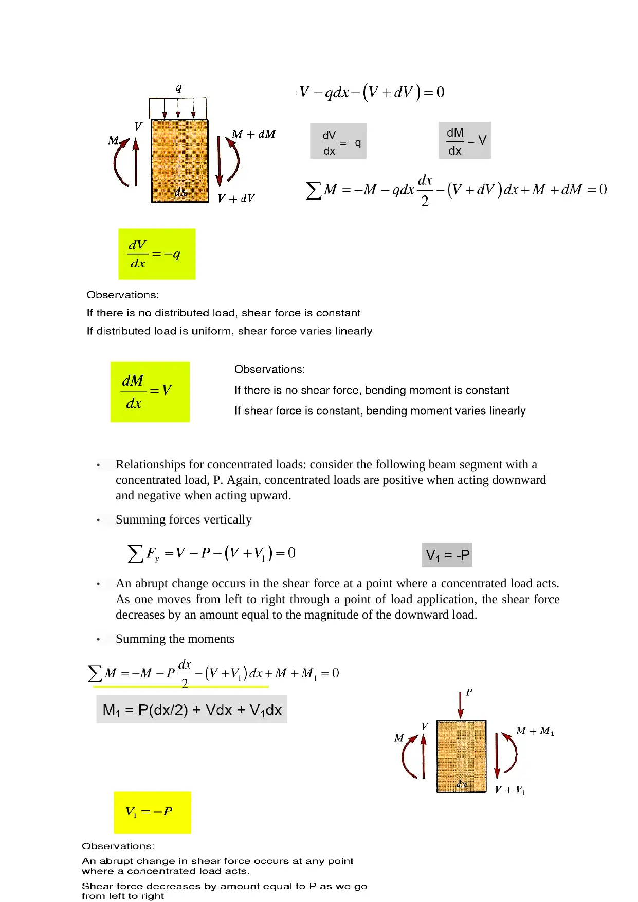
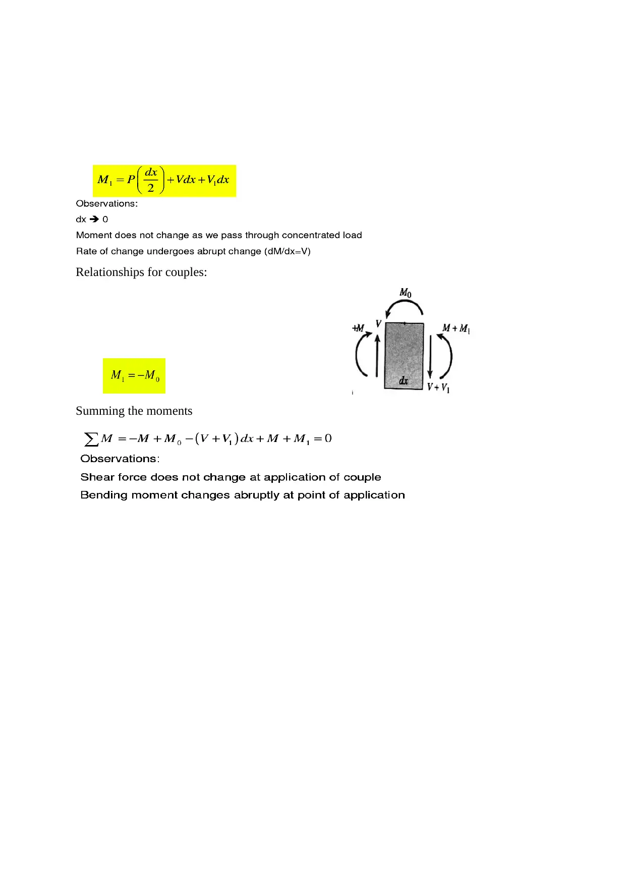
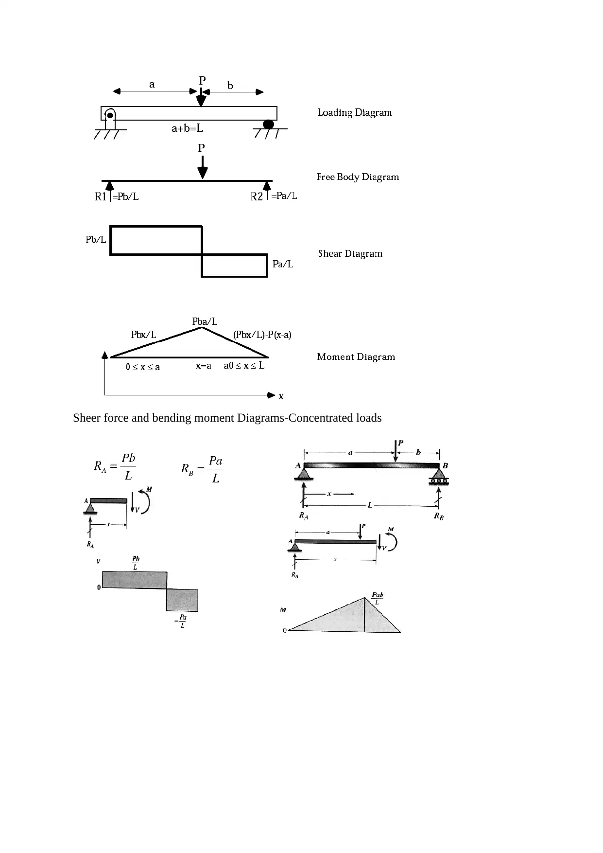
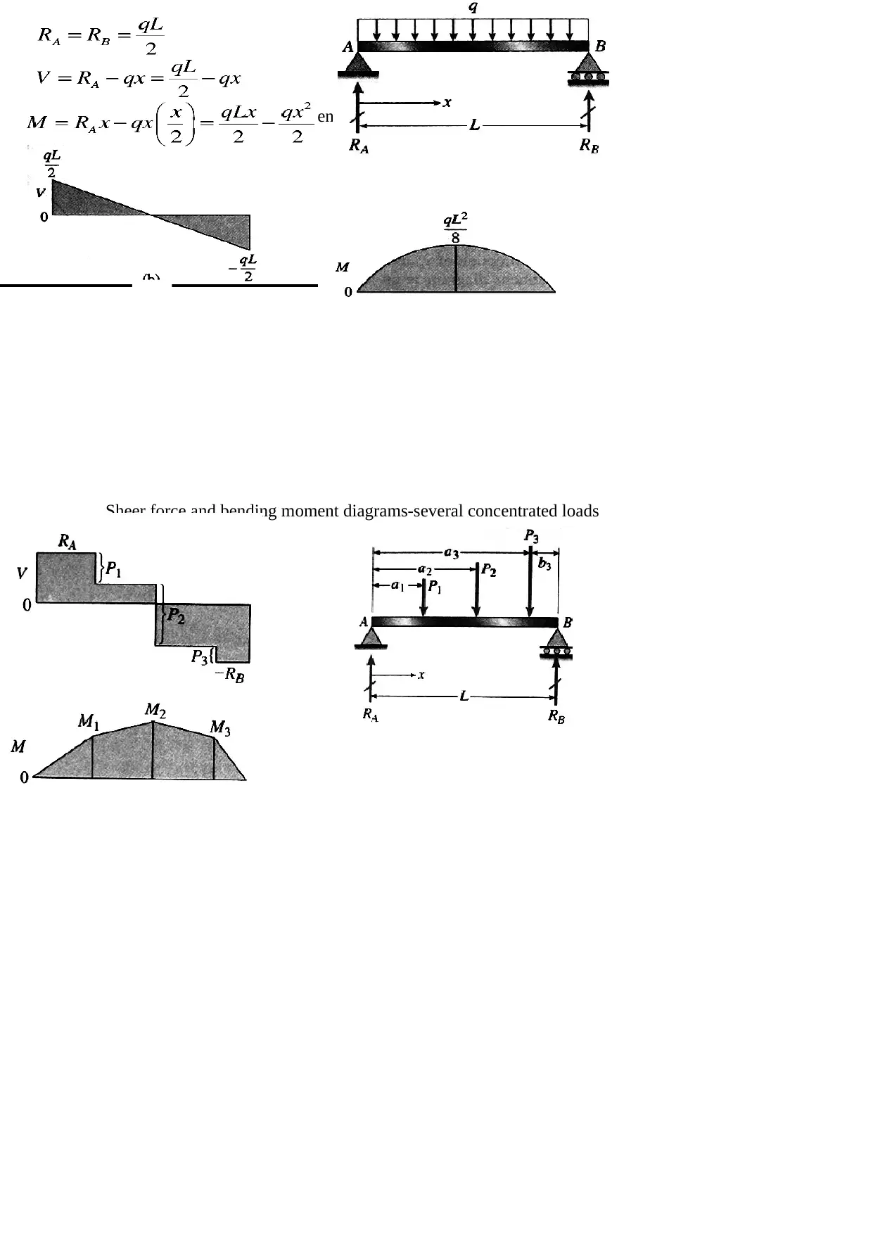
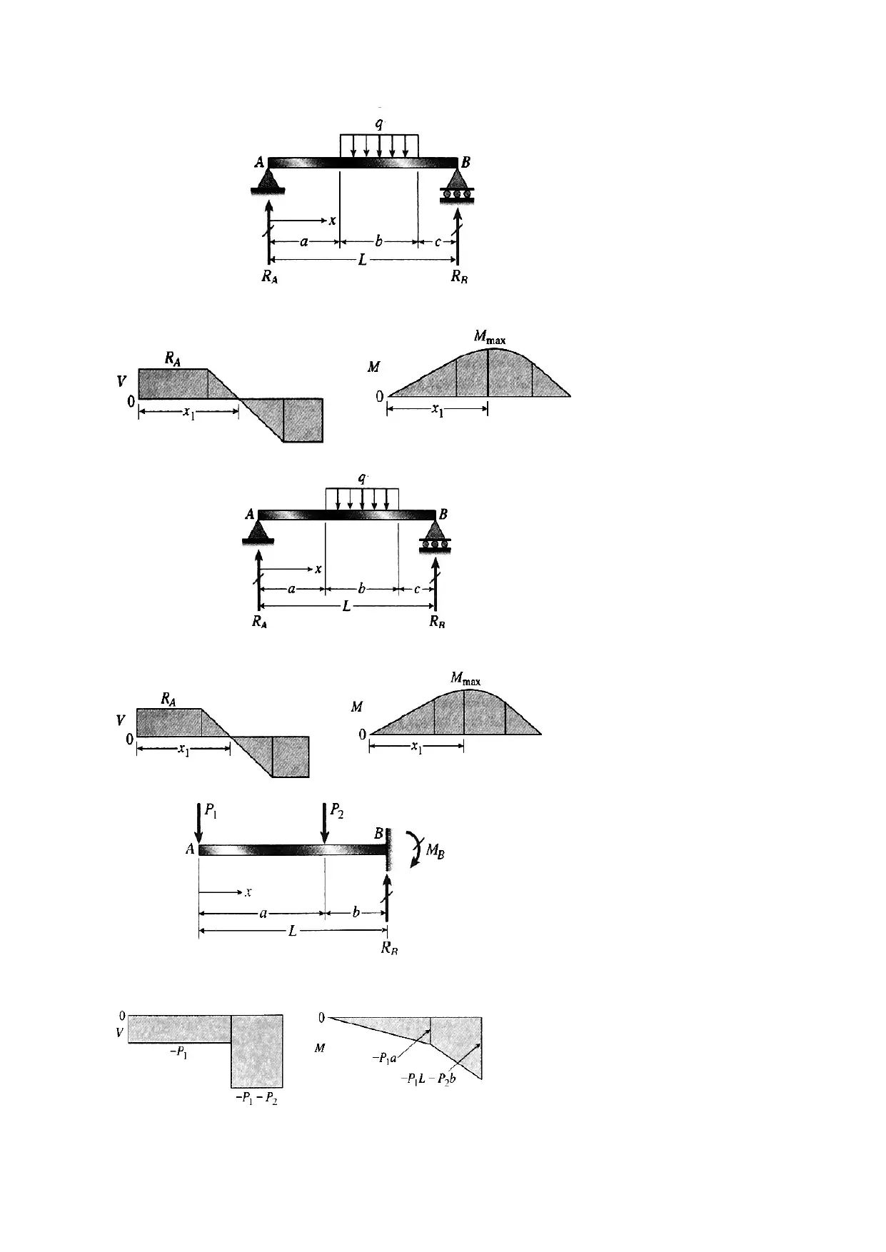
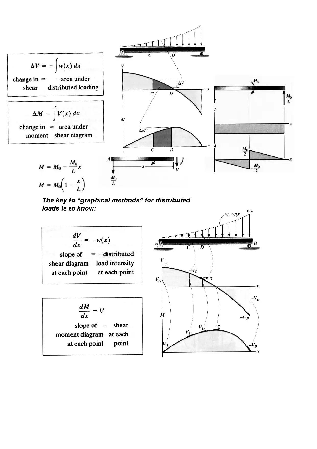
This document presents an analysis of static engineering systems, focusing on two primary areas: the mechanics of beams and the principles of electrical circuits. The beam analysis section explores different types of loading (axial, bending, torsional) and beam classifications based on support methods. It delves into concepts such as direct stress, direct strain, Hooke's law, and Poisson's ratio, with detailed explanations of shear force and bending moment diagrams for various load types. The electrical circuits section introduces fundamental concepts like voltage, current, and Kirchhoff's laws, alongside AC and DC circuit analysis. It describes circuit elements like resistors, inductors, and capacitors, with equations for their behavior. Furthermore, it touches on complex numbers in AC analysis and phasor diagrams. The document provides a comprehensive overview of the principles and analysis techniques for both structural and electrical engineering systems.
Document Page
STATIC
ENGINEERING
SYSTEM
tabler-icon-diamond-filled.svg

Paraphrase This Document

Need a fresh take? Get an instant paraphrase of this document with our AI Paraphraser
Document Page
TASK 1
Simple supported beams: Load bearing structure can be of any forms. They are mainly of
three types like axial loading, bending and torsional loading which are being discussed.
Axial loading: this occurs when an object is loaded so that the force is normal t the axis that
is fixed. Considering statics, equal force should be there at wall and applied part.
Figure 1: Bar (a) in tension (b) in compression
The part which is in the tension is known as the tie and the part which is in compression is
strut.
Direct stress: Direct stress are the stress which act normal to the plane on which they act.
These can be either tensile if the applied force is in the direction as the elongate the bar or it
can be compressive stress if the bar is compressed. It is defined as the A where A is
the cross sectional area. Its unit is force per unit area or N/m2 or Pascal.
Direct strain: the axial loaded bar undergoes a change in length, increasing in length when in
tension and decreasing in length when in compression it is termed as the Direct strain Ɛ.
Ɛ= e/L. its dimension less number and are very small in numbers.
Figure 2: (a) Unstratched (b) stratched bar
Document Page
Hooke’s Law: strain proportional to stress producing it. The ratio of the
direct stress produced is called the modulus of elasticity E:
It has no unit and strain unit is in giga-pascal.
Axially loaded members: considering the parallel and series combination
Members of Parallel: For parallel it is considered as the compound bars.
Figure 3: Example of a compound bar.
For compound the load F is shared by two members. Total force is
FA + FB = F.
Hence total force can be written as
Thus Hooke’s law where EA and EB are the modulus of
elasticity.
Document Page
Members of Series: suppose two materials of different material and cross-section. It will be in
Equilibrium condition and the force of stretching the A and B are same to C.
Figure 4: Members of series.
Poisson’s ratio: when material is longitudinal stretched it contracts in a transverse direction.
The ration of the transverse strain to the longitudinal strain is called Poisson’s ratio.
Figure 5 transverse contraction as a result of longitudinal stretching
the negative sign as one strains
is tensile and other is compressive. For most engineering metal its
value is 0.3.
Types of columns: Depending on the mode of failure, columns can be categorised in the
following ways
(a) a short column: a column which will fail in true compression
(b) a long column: a column which buckles before full compressive strength is reached
Types of beams: Beams can be classified according to the manner in which they supported
tabler-icon-diamond-filled.svg

Paraphrase This Document

Need a fresh take? Get an instant paraphrase of this document with our AI Paraphraser
Document Page
Figure 6: Various types of Beams
Beams used in building and bridges
- Girders: Usually the most important beams, which are frequently ag wide spacing
- Joists: Usually less important beams, which are closely spaced, frequently with truss-
type webs.
- Stringers: Longitudinal bridge beams spanning between floor beams.
- Purlins: Roof beams spanning between trusses.
- Girts: Horizontal wall beams to wind on the side of and industrial building
- Lintels: Members supporting a wall over window or door openings.
Loads: Loads can be applied on the beans in one of the following.
Figure 7: types of load
Document Page
Sheer force and bending moments:
When a beam is loaded by forces or couples, internal
stresses and strains are created. Consider a cantilever
arrangement
It is convenient to reduce the resultant to a shear force, V,
and a bending moment, M.
Sign Convention:
Positive shear forces always deform right hand face downward with respect to the left
hand face. Positive shear stress acts clockwise while negative shear stress acts
counter-clockwise
Positive bending moments always elongate the lower section of the beam. Positive
moment compresses upper (sagging moments) whereas negative moment compresses
lower (hogging moments)
Relationships for continuous loads: Consider the following beam segment with a
uniformly distributed load with load intensity q. Note that distributed loads are positive
when acting downward and negative when acting upward.
Summing forces vertically
Summing moments and discarding products of differentials because they are
negligible compared to other terms
Document Page
Relationships for concentrated loads: consider the following beam segment with a
concentrated load, P. Again, concentrated loads are positive when acting downward
and negative when acting upward.
Summing forces vertically
An abrupt change occurs in the shear force at a point where a concentrated load acts.
As one moves from left to right through a point of load application, the shear force
decreases by an amount equal to the magnitude of the downward load.
Summing the moments
tabler-icon-diamond-filled.svg

Paraphrase This Document

Need a fresh take? Get an instant paraphrase of this document with our AI Paraphraser
Document Page
Relationships for couples:
Summing the moments
Document Page
Sheer force and bending moment Diagrams-Concentrated loads
Document Page
Sheer force and bending moment diagrams-Uniform loads
Sheer force and bending moment diagrams-several concentrated loads
tabler-icon-diamond-filled.svg

Paraphrase This Document

Need a fresh take? Get an instant paraphrase of this document with our AI Paraphraser
Document Page
Document Page
chevron_up_icon
1 out of 32
circle_padding
hide_on_mobile
zoom_out_icon
[object Object]