Series RL and RLC Circuit Simulation and Analysis Report

Verified

Added on  2022/10/01

|11
|666
|20
Practical Assignment
AI Summary
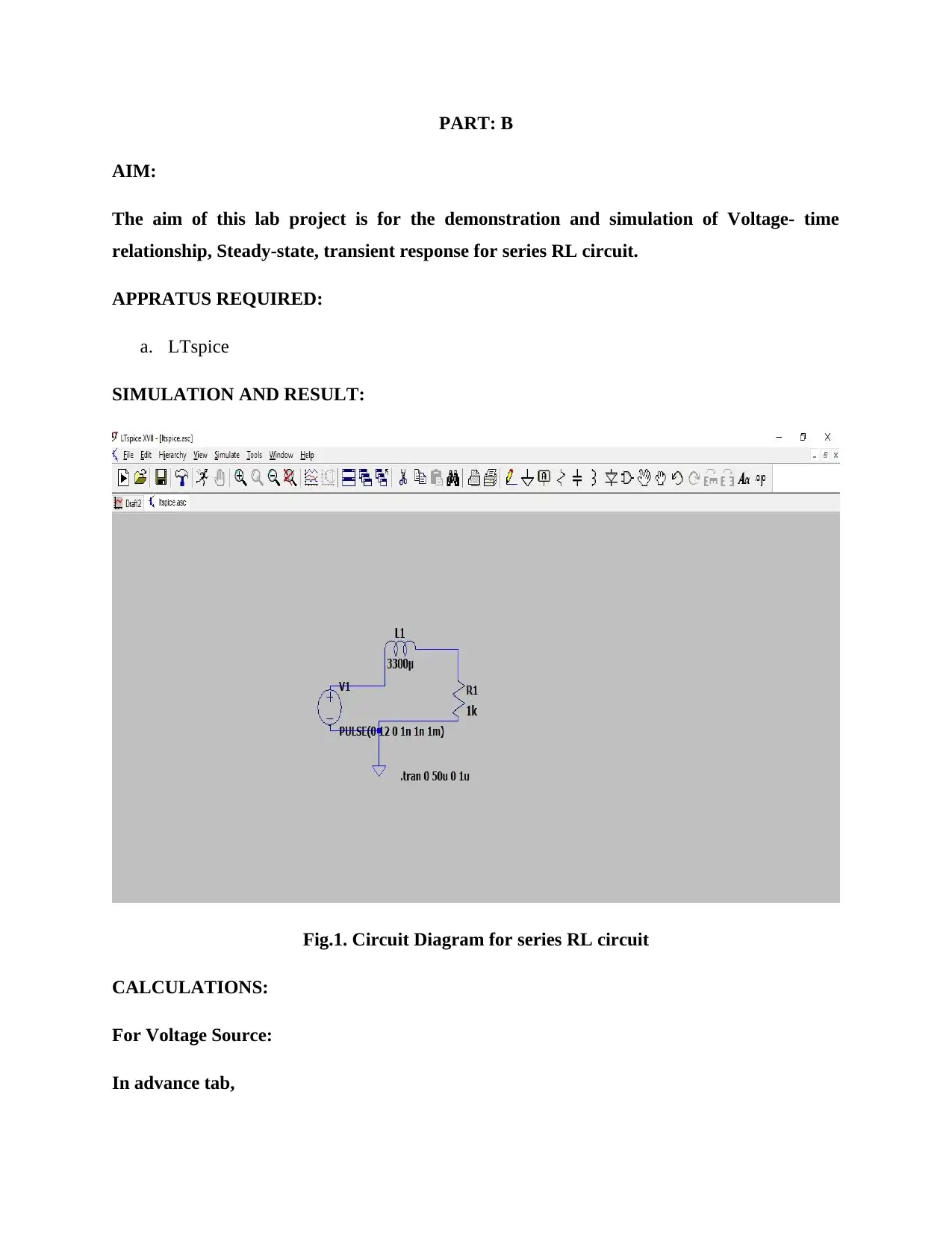
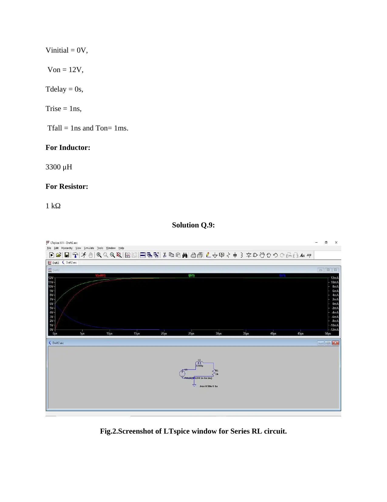
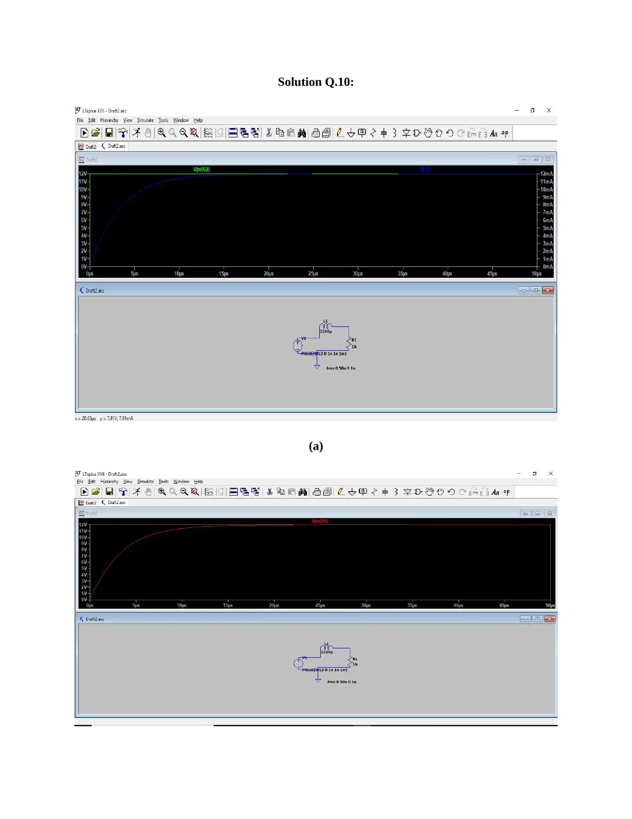
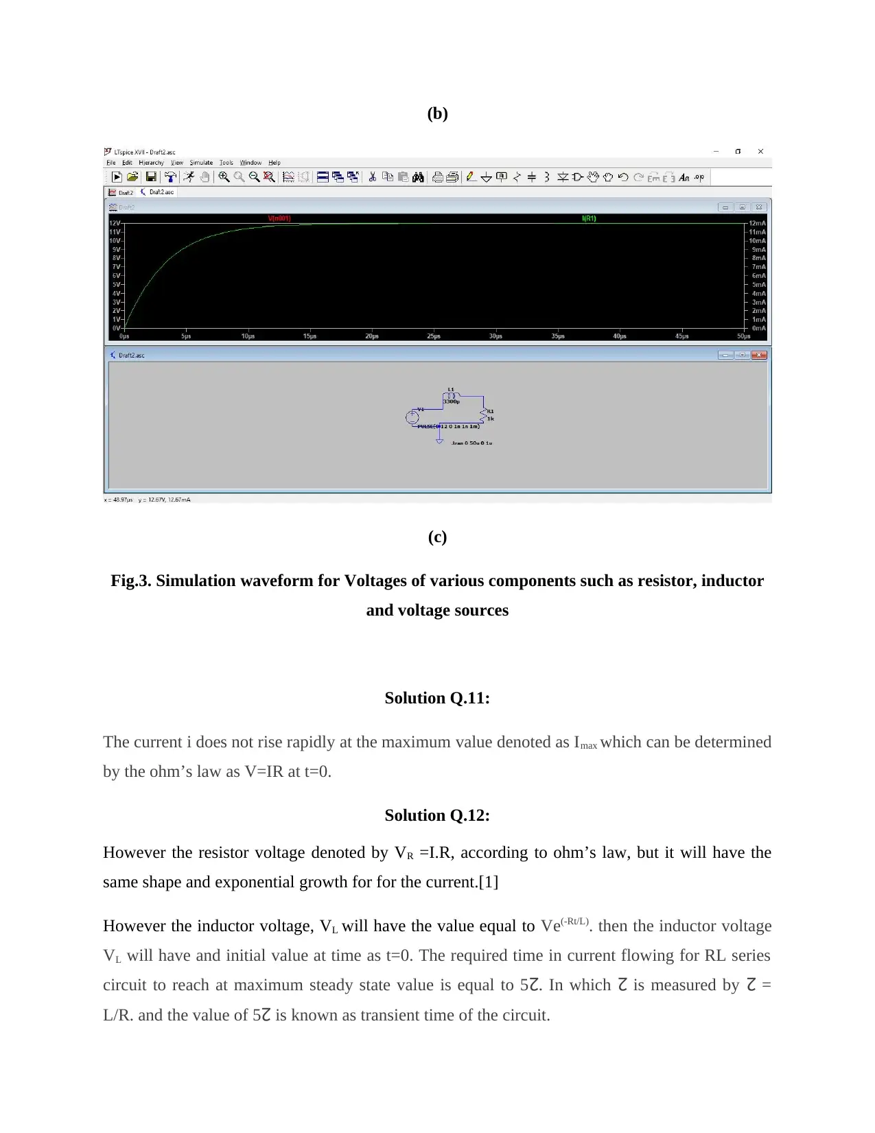
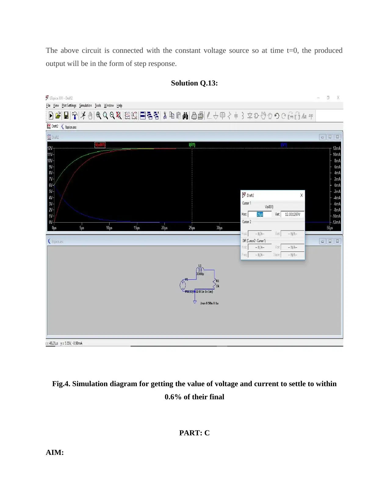
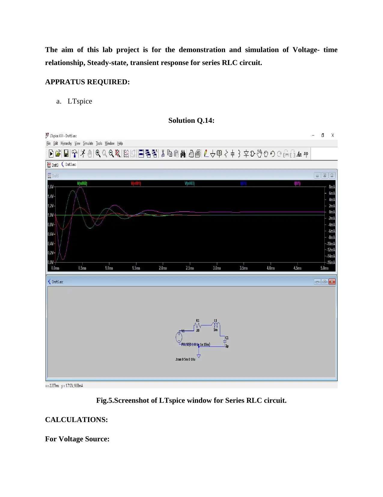
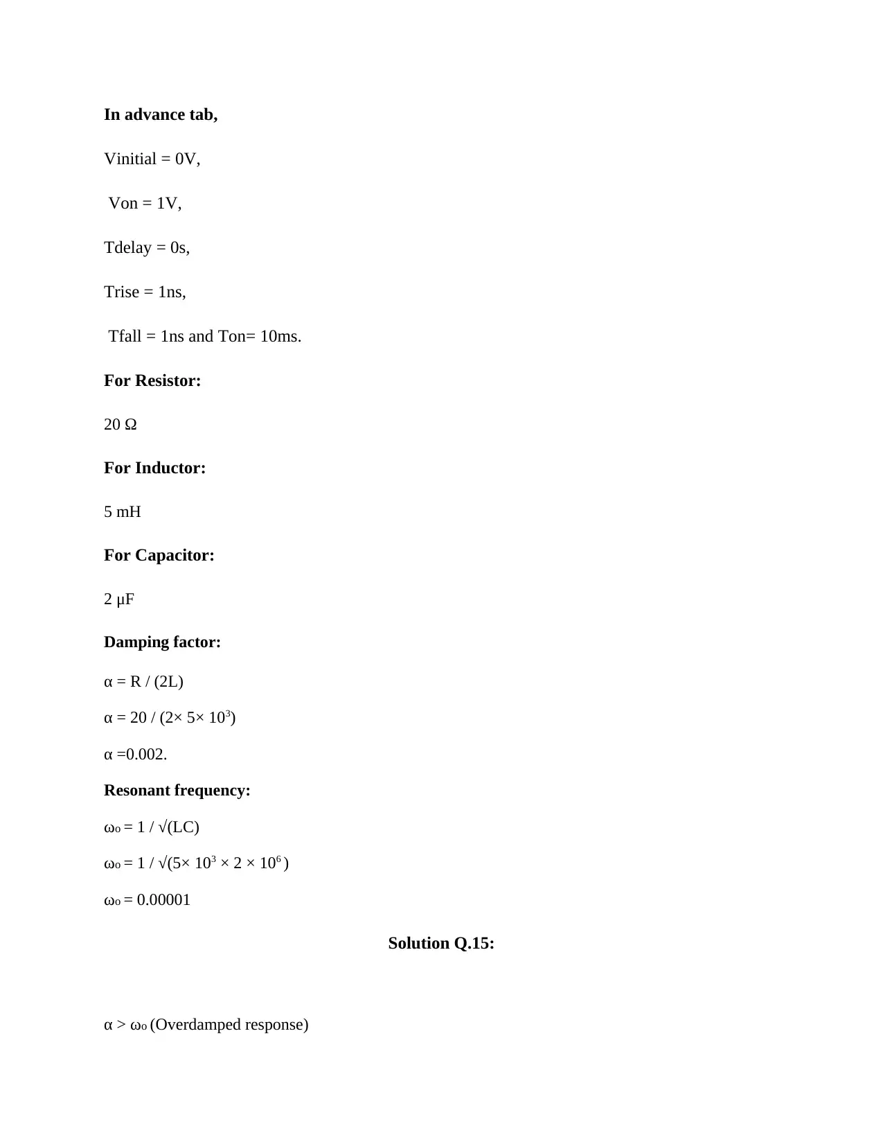
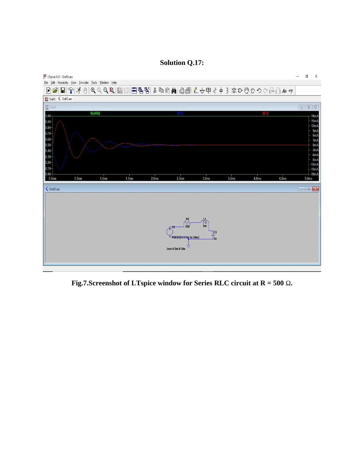
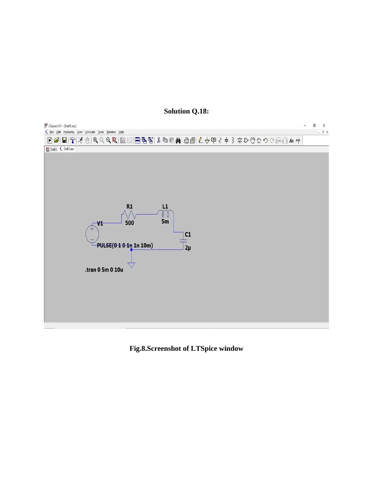
This assignment report details the simulation and analysis of series RL and RLC circuits using LTspice. Part B focuses on demonstrating the voltage-time relationship, steady-state, and transient response of an RL circuit, including calculations and waveform analysis for voltage sources, resistors, and inductors. Part C extends this to RLC circuits, examining the impact of damping factors and resonant frequencies on the circuit's response. The report includes screenshots of the LTspice simulations, calculations, and discussions on the behavior of current and voltage in these circuits, with references to relevant literature. The assignment covers overdamped and critically damped responses and the determination of transient time.
Document Page
PART: B
AIM:
The aim of this lab project is for the demonstration and simulation of Voltage- time
relationship, Steady-state, transient response for series RL circuit.
APPRATUS REQUIRED:
a. LTspice
SIMULATION AND RESULT:
Fig.1. Circuit Diagram for series RL circuit
CALCULATIONS:
For Voltage Source:
In advance tab,
tabler-icon-diamond-filled.svg

Paraphrase This Document

Need a fresh take? Get an instant paraphrase of this document with our AI Paraphraser
Document Page
Vinitial = 0V,
Von = 12V,
Tdelay = 0s,
Trise = 1ns,
Tfall = 1ns and Ton= 1ms.
For Inductor:
3300 μH
For Resistor:
1 kΩ
Solution Q.9:
Fig.2.Screenshot of LTspice window for Series RL circuit.
Document Page
Solution Q.10:
(a)
Document Page
(b)
(c)
Fig.3. Simulation waveform for Voltages of various components such as resistor, inductor
and voltage sources
Solution Q.11:
The current i does not rise rapidly at the maximum value denoted as Imax which can be determined
by the ohm’s law as V=IR at t=0.
Solution Q.12:
However the resistor voltage denoted by VR =I.R, according to ohm’s law, but it will have the
same shape and exponential growth for for the current.[1]
However the inductor voltage, VL will have the value equal to Ve(-Rt/L). then the inductor voltage
VL will have and initial value at time as t=0. The required time in current flowing for RL series
circuit to reach at maximum steady state value is equal to 5 . In which is measured by =
L/R. and the value of 5 is known as transient time of the circuit.
tabler-icon-diamond-filled.svg

Paraphrase This Document

Need a fresh take? Get an instant paraphrase of this document with our AI Paraphraser
Document Page
The above circuit is connected with the constant voltage source so at time t=0, the produced
output will be in the form of step response.
Solution Q.13:
Fig.4. Simulation diagram for getting the value of voltage and current to settle to within
0.6% of their final
PART: C
AIM:
Document Page
The aim of this lab project is for the demonstration and simulation of Voltage- time
relationship, Steady-state, transient response for series RLC circuit.
APPRATUS REQUIRED:
a. LTspice
Solution Q.14:
Fig.5.Screenshot of LTspice window for Series RLC circuit.
CALCULATIONS:
For Voltage Source:
Document Page
In advance tab,
Vinitial = 0V,
Von = 1V,
Tdelay = 0s,
Trise = 1ns,
Tfall = 1ns and Ton= 10ms.
For Resistor:
20 Ω
For Inductor:
5 mH
For Capacitor:
2 μF
Damping factor:
α = R / (2L)
α = 20 / (2× 5× 103)
α =0.002.
Resonant frequency:
ωo = 1 / √(LC)
ωo = 1 / √(5× 103 × 2 × 106 )
ωo = 0.00001
Solution Q.15:
α > ωo (Overdamped response)
tabler-icon-diamond-filled.svg

Paraphrase This Document

Need a fresh take? Get an instant paraphrase of this document with our AI Paraphraser
Document Page
Hence it is an overdamped response.
Solution Q.16:
Fig.6.Screenshot of LTspice window for Series RLC circuit at R = 100 Ω.
At the value of R= 100 Ω.
The response can be described as critically damped.
In the condition at:
α = ωo (Critically damped response)
Document Page
Solution Q.17:
Fig.7.Screenshot of LTspice window for Series RLC circuit at R = 500 Ω.
Document Page
Solution Q.18:
Fig.8.Screenshot of LTSpice window
tabler-icon-diamond-filled.svg

Paraphrase This Document

Need a fresh take? Get an instant paraphrase of this document with our AI Paraphraser
Document Page
REFERENCES
[1] J.F.G. Aguilar, A. Atangana, V. F. M. Delgado.( 2017, April). “Electrical circuits RC, LC,
and RL described by Atangana–Baleanu fractional derivatives.” International journal of circuit
theory and applications [Online]. Available:
https://onlinelibrary.wiley.com/doi/full/10.1002/cta.2348
[2] A. G. RADWAN. (2012, July).” STABILITY ANALYSIS OF THE FRACTIONAL-ORDER
RLβCα CIRCUIT.” Journal of Fractional Calculus and Applications [Online]. Vol. 3, Issue no. 1,
pp. 1–15. Available:
https://www.researchgate.net/publication/267368978_Stability_analysis_of_the_fractional
order_RLC_circuit/link/546688360cf2f5eb180170c6/download
chevron_up_icon
1 out of 11
circle_padding
hide_on_mobile
zoom_out_icon
[object Object]