Electrical Engineering: Circuit Analysis, Waveforms, and Inductors

Verified

Added on  2023/01/19

|8
|423
|46
Homework Assignment
AI Summary
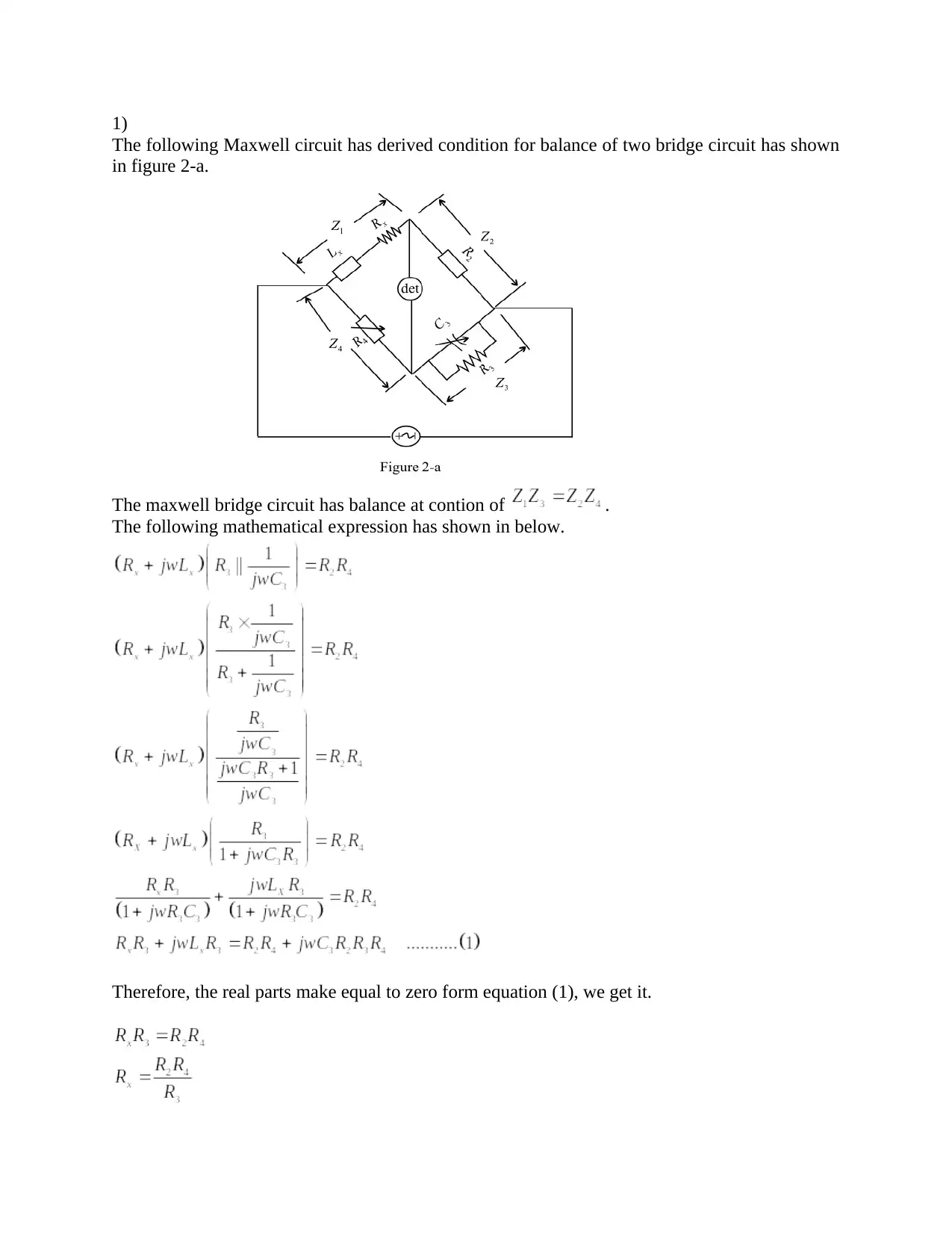
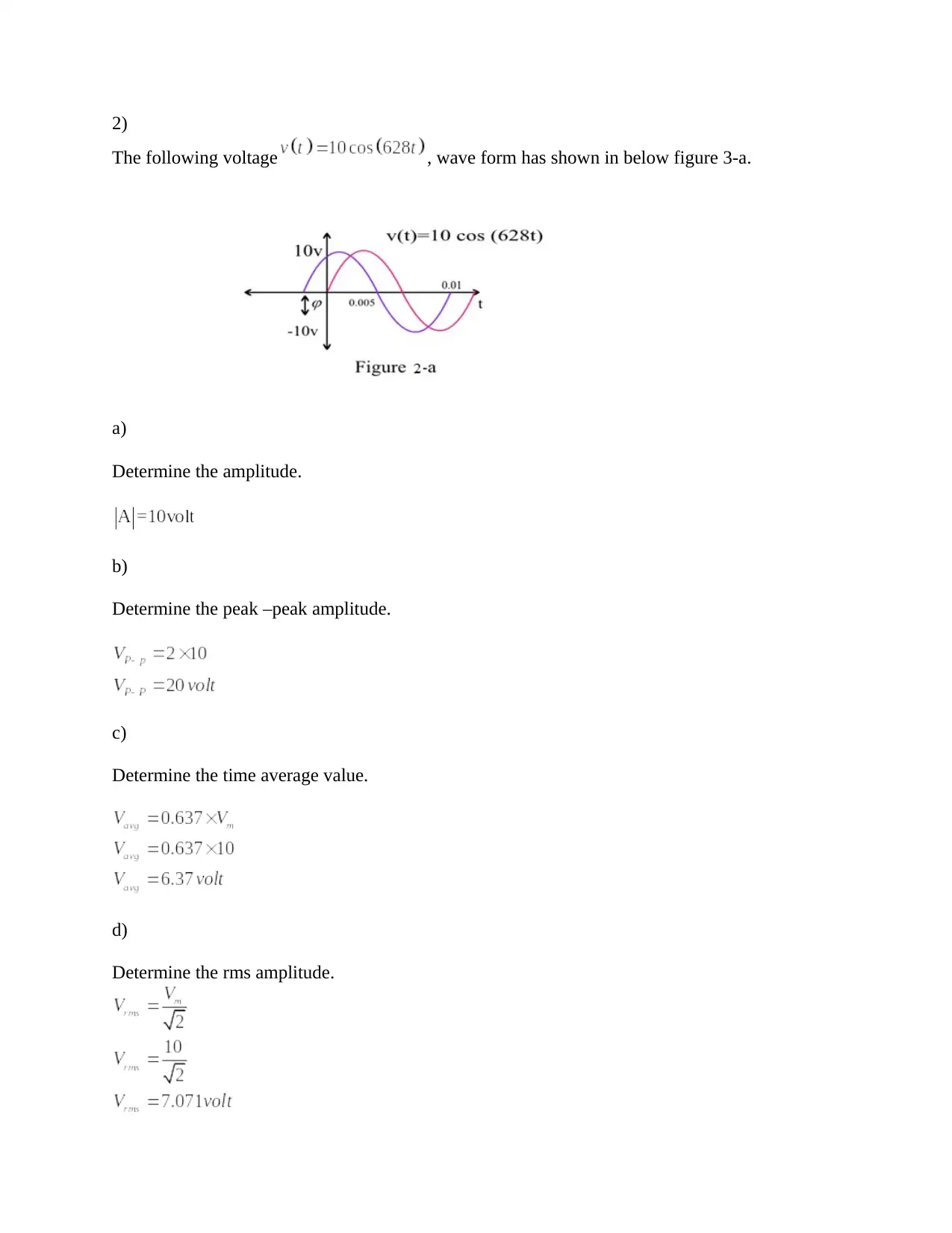
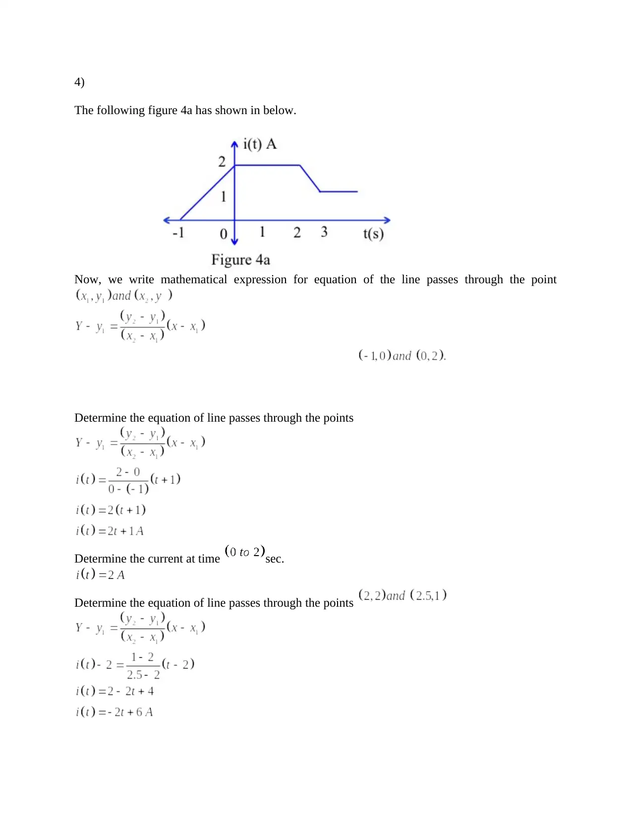
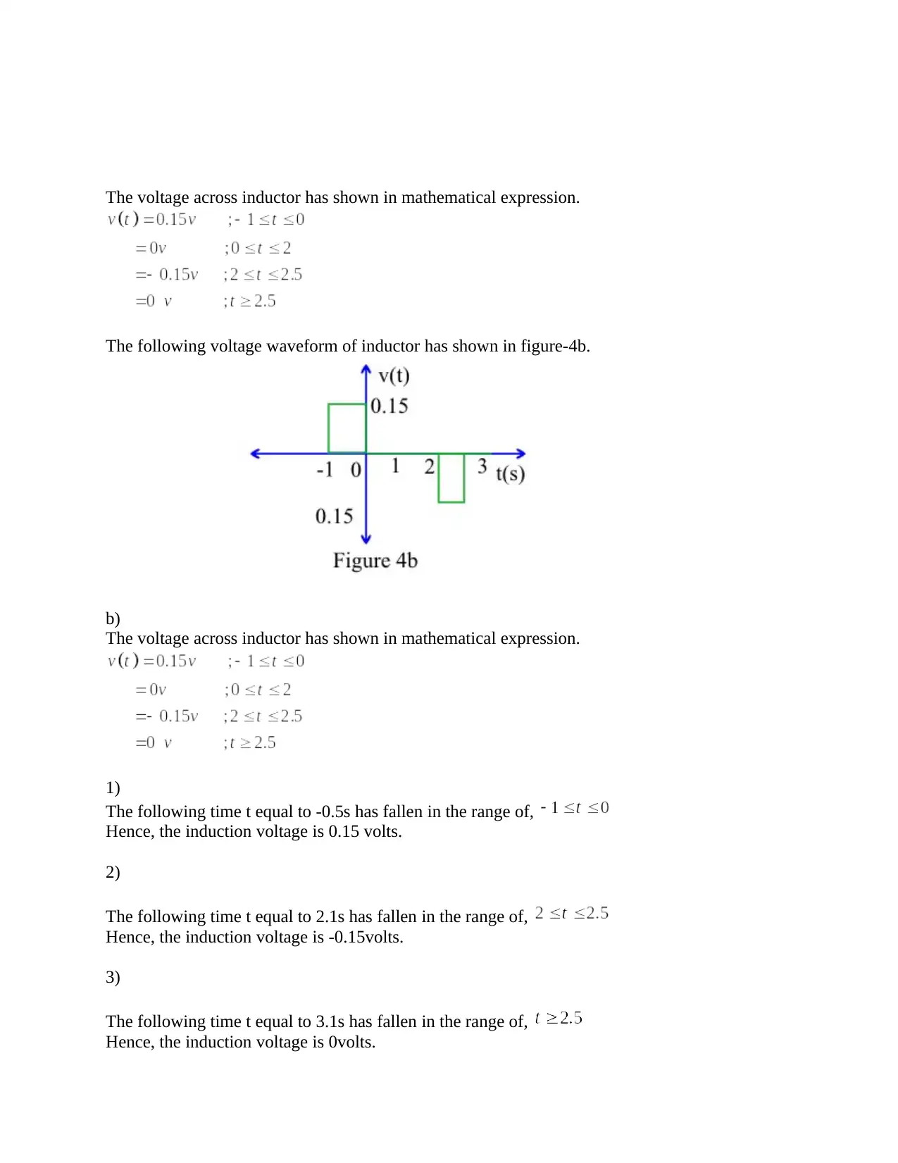
This document presents a detailed solution to an electrical engineering assignment. The assignment covers the analysis of Maxwell and Wien bridge circuits, including the derivation of balance conditions. It also includes the analysis of a voltage waveform, determining its amplitude, peak-to-peak amplitude, time average value, RMS amplitude, frequency, and angular frequency. Furthermore, the assignment involves calculating the current through a capacitor and determining the equation of a line passing through given points. Finally, the solution addresses the calculation of voltage across an inductor at different time intervals based on a provided waveform, along with the corresponding mathematical expressions and calculations for inductor voltage at specific time points.
Document Page
1)
The following Maxwell circuit has derived condition for balance of two bridge circuit has shown
in figure 2-a.
The maxwell bridge circuit has balance at contion of .
The following mathematical expression has shown in below.
Therefore, the real parts make equal to zero form equation (1), we get it.
tabler-icon-diamond-filled.svg

Paraphrase This Document

Need a fresh take? Get an instant paraphrase of this document with our AI Paraphraser
Document Page
Therefore, the imaginary parts make equal to zero form equation (1), we get it.
The following Wien series circuit has derived condition for balance of two bridge circuit has
shown in figure 2-b.
The Wien series bridge circuit has balance at contion of .
The following mathematical expression has shown in below.
Therefore, the real parts make equal to zero form equation (1), we get it.
Therefore, the imaginary parts make equal to zero form equation (1), we get it.
Document Page
2)
The following voltage , wave form has shown in below figure 3-a.
a)
Determine the amplitude.
b)
Determine the peak –peak amplitude.
c)
Determine the time average value.
d)
Determine the rms amplitude.
Document Page
e)
Determine the frequency.
f)
Determine the angular frequency.
3)
Determine the current following through a 220 nF if its voltage .
tabler-icon-diamond-filled.svg

Paraphrase This Document

Need a fresh take? Get an instant paraphrase of this document with our AI Paraphraser
Document Page
4)
The following figure 4a has shown in below.
Now, we write mathematical expression for equation of the line passes through the point
Determine the equation of line passes through the points
Determine the current at time sec.
Determine the equation of line passes through the points
Document Page
Now, we write mathematical expression for the above equation
Determine the voltage across inductor at time .
Determine the voltage across inductor at time
Document Page
The voltage across inductor has shown in mathematical expression.
The following voltage waveform of inductor has shown in figure-4b.
b)
The voltage across inductor has shown in mathematical expression.
1)
The following time t equal to -0.5s has fallen in the range of,
Hence, the induction voltage is 0.15 volts.
2)
The following time t equal to 2.1s has fallen in the range of,
Hence, the induction voltage is -0.15volts.
3)
The following time t equal to 3.1s has fallen in the range of,
Hence, the induction voltage is 0volts.
tabler-icon-diamond-filled.svg

Paraphrase This Document

Need a fresh take? Get an instant paraphrase of this document with our AI Paraphraser
Document Page
chevron_up_icon
1 out of 8
circle_padding
hide_on_mobile
zoom_out_icon
[object Object]