Comprehensive Analysis: Electrical Drawings, Standards, and Practices
VerifiedAdded on 2024/06/10
|27
|5525
|351
Homework Assignment
AI Summary
This assignment comprehensively covers various aspects of electrical drawings and standards used in the electro-technology industry. It begins by detailing the information included in site plans and floor plans, emphasizing the importance of standard symbols, scales, and dimensions. The discussion extends to electrical drawings, differentiating between block diagrams, circuit diagrams, wiring diagrams, and ladder diagrams, while also highlighting Australian standard symbols. Furthermore, it addresses cable schedules, their purpose, and the information they contain, including cable types, sizes, and lengths. The assignment also elaborates on the purpose of circuit and wiring diagrams, the conventions used, and the steps involved in creating switching charts. Finally, it explores different building types and considerations for electrical work within them, such as metal frame, double brick, and brick veneer constructions. This document is available on Desklib, where students can access a wide range of solved assignments and past papers.

Assessment
Paraphrase This Document
Need a fresh take? Get an instant paraphrase of this document with our AI Paraphraser
WRITTEN ACTIVITY
Task 1 - Architectural drawings
1. What information should be included in a site plan?
Site plan should include the standard format and scale which is developed from the standard
symbols and signs. It includes the size of total area of the building and land associated to the site.
It also includes the distance calculated between the property boundaries and structures. It also
includes the contours that are present on the land at site. It also includes the land features,
amenities, structures, scale, symbols and drawings.
2. What information should be included on a floor plan?
Floor plans are the scale drawings of the floor of the building which are structured and
standardized to develop design. It contains the dimensions of wall on the basis of external and
internal size. It also provides the details of the windows, doors, appliances, electrical fittings and
all conventions.
3. When using an architectural floor plan in order to determine the location and requirements
for the power and lighting or communications / audio/ video layouts required in a domestic
installation, what will you need to take into consideration?
The important requirements of the architectural plan includesome of the major requirements for
the determination of the location and other requirements. They are: symbols which are from
standard convections, scale of the area, floor plan details, and details of the wire and circuit
connections.
4. Discuss the following in regards to site plans:
Service point: This point is responsible for the detection of the accurate location of
the meeting point of the provider of electrical wholesale and electrical wiring
systems of consumers.
Consumer mains: This is the important connection which is the point of mains
supply and it is supplied to the particular customer drawn from the service point.
Main switchboard: It contains the elements of the consumer mains and also related
to the electrical cables associated to the full the building. It mainly contains the main
fuses, electrical connection of the mainline and backline of building, power
connection, measuring devices of the power consumed, safety switches and much
more
.
Distribution boards: It is one of the important part of the house wiring system and
has the responsibility of keep separating the individual circuit from the main supply.
Its location is same as where the main switchboard is placed.
1
Builder’s supplies: At the building in some cases, there is the requirement of the
electricity supply so that it can be utilized for the purpose of the construction before
the process of the wiring at the located property.
5. What is the most common scale used for floor plans? What does it represent?
There are some standard forms which can be used for the floor plans. And with this, the
commonly used scaling is 1: 100. It can be considered as the standard format and can be very
helpful for the measurement of different items. Here, 1 denotes the one centimetre and the 100
denotes the 1 meter. To understand this, let’s take an example of 5 m room where it will be
represented as 5cm on the floor plan. The correct scale should be defined prior to the
development of the floor plan where it can be ensured that details should be provided initially so
that planning and calculation can be done with accuracy.
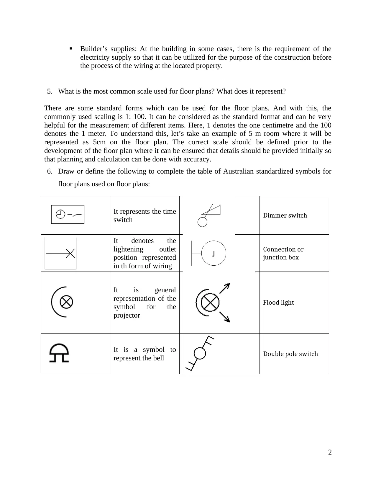
6. Draw or define the following to complete the table of Australian standardized symbols for
floor plans used on floor plans:
It represents the time
switch Dimmer switch
It denotes the
lightening outlet
position represented
in th form of wiring
Connection or
junction box
It is general
representation of the
symbol for the
projector
Flood light
It is a symbol to
represent the bell Double pole switch
2
electricity supply so that it can be utilized for the purpose of the construction before
the process of the wiring at the located property.
5. What is the most common scale used for floor plans? What does it represent?
There are some standard forms which can be used for the floor plans. And with this, the
commonly used scaling is 1: 100. It can be considered as the standard format and can be very
helpful for the measurement of different items. Here, 1 denotes the one centimetre and the 100
denotes the 1 meter. To understand this, let’s take an example of 5 m room where it will be
represented as 5cm on the floor plan. The correct scale should be defined prior to the
development of the floor plan where it can be ensured that details should be provided initially so
that planning and calculation can be done with accuracy.
6. Draw or define the following to complete the table of Australian standardized symbols for
floor plans used on floor plans:
It represents the time
switch Dimmer switch
It denotes the
lightening outlet
position represented
in th form of wiring
Connection or
junction box
It is general
representation of the
symbol for the
projector
Flood light
It is a symbol to
represent the bell Double pole switch
2
⊘ This is a preview!⊘
Do you want full access?
Subscribe today to unlock all pages.
Trusted by 1+ million students worldwide
Task 2 - Electrical drawings
1. Describe the purpose of each of the following types of electrical drawings:
a. Block diagrams: This diagram includes a series of blocks which is used to denote the
different electrical components for the project of installation and its designing. They can
be developed in details including the basic and smallest detail of the components
required. It is responsible for demonstrating the main component overview with
systematic diagram of circuit.
b. Circuit diagrams: These diagrams are the pictorial representation of the circuit which is
going to be established. It also contains the design which is developed from the standard
formatsto show the layout of all the components of the electrical circuits. This diagram
can be used for the installation and design diagram.
c. Wiring diagrams: These type of diagrams uses the standard symbol and line to
representpossible wiring connection and associated components. It is going to be used
for the wiring with building planning and installation of the electrical project in detailed
or simple form.
d. Ladder diagrams: This diagram is represented in the form of the ladder. Here the two
vertical poles denote the source of power. The current carrying conductor is represented
by the left rail and the grounding is represented by the right side. Voltage connection
and entire circuit is represented by the horizontal rungs. It is used for representing the
diagrams of the maintenance and troubleshooting.
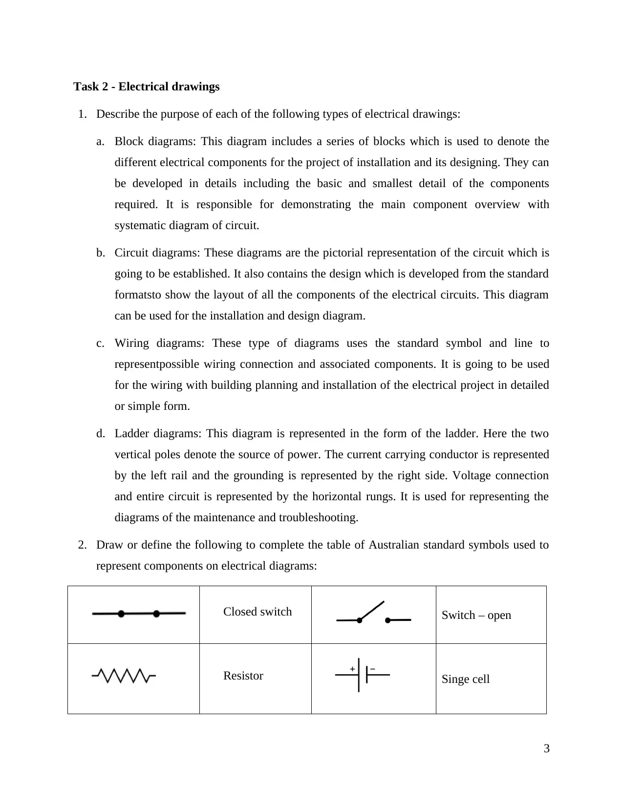
2. Draw or define the following to complete the table of Australian standard symbols used to
represent components on electrical diagrams:
Closed switch Switch – open
Resistor Singe cell
3
1. Describe the purpose of each of the following types of electrical drawings:
a. Block diagrams: This diagram includes a series of blocks which is used to denote the
different electrical components for the project of installation and its designing. They can
be developed in details including the basic and smallest detail of the components
required. It is responsible for demonstrating the main component overview with
systematic diagram of circuit.
b. Circuit diagrams: These diagrams are the pictorial representation of the circuit which is
going to be established. It also contains the design which is developed from the standard
formatsto show the layout of all the components of the electrical circuits. This diagram
can be used for the installation and design diagram.
c. Wiring diagrams: These type of diagrams uses the standard symbol and line to
representpossible wiring connection and associated components. It is going to be used
for the wiring with building planning and installation of the electrical project in detailed
or simple form.
d. Ladder diagrams: This diagram is represented in the form of the ladder. Here the two
vertical poles denote the source of power. The current carrying conductor is represented
by the left rail and the grounding is represented by the right side. Voltage connection
and entire circuit is represented by the horizontal rungs. It is used for representing the
diagrams of the maintenance and troubleshooting.
2. Draw or define the following to complete the table of Australian standard symbols used to
represent components on electrical diagrams:
Closed switch Switch – open
Resistor Singe cell
3
Paraphrase This Document
Need a fresh take? Get an instant paraphrase of this document with our AI Paraphraser
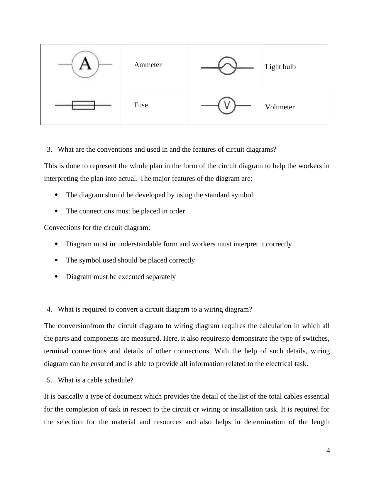
Ammeter Light bulb
Fuse Voltmeter
3. What are the conventions and used in and the features of circuit diagrams?
This is done to represent the whole plan in the form of the circuit diagram to help the workers in
interpreting the plan into actual. The major features of the diagram are:
The diagram should be developed by using the standard symbol
The connections must be placed in order
Convections for the circuit diagram:
Diagram must in understandable form and workers must interpret it correctly
The symbol used should be placed correctly
Diagram must be executed separately
4. What is required to convert a circuit diagram to a wiring diagram?
The conversionfrom the circuit diagram to wiring diagram requires the calculation in which all
the parts and components are measured. Here, it also requiresto demonstrate the type of switches,
terminal connections and details of other connections. With the help of such details, wiring
diagram can be ensured and is able to provide all information related to the electrical task.
5. What is a cable schedule?
It is basically a type of document which provides the detail of the list of the total cables essential
for the completion of task in respect to the circuit or wiring or installation task. It is required for
the selection for the material and resources and also helps in determination of the length
4
required. Also helps in planning and developing the procedure required for the installation
procedure.
6. What information will be listed on the cable schedule regarding each of the cables included?
The information in the cable schedule includes thedetails of the cable required for the
development of the electrical task. It majorly includes thenumber of cables required in addition
to details of their types. It also provides the details of the size and length of each cable in
addition to gland type and their size.
7. What steps are involved in developing a cable schedule for a given installation?
There are some of the steps required for the cable schedule and can be used for the installation of
electrical task. Those steps are:
The possible cable routes and access points must be determined
For the every connection, identify the required cable
Find the points where the connection is required
Identify all the types of cable
Specify the cable features
Finally develop a table including the information described above
5
⊘ This is a preview!⊘
Do you want full access?
Subscribe today to unlock all pages.
Trusted by 1+ million students worldwide
Task 3 - Circuit diagrams
1. What is the purpose of circuit diagrams in the electro technology industry?
The purpose of the circuit diagram is to provide help to the electrical workers to provide support
in understanding the electrical task at the electro technology industry. It demonstrates the basic
component of the circuit and the set up order of the components.
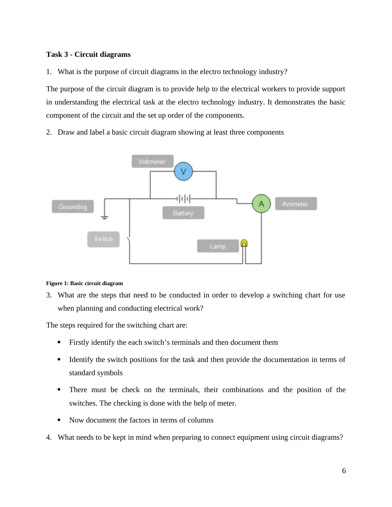
2. Draw and label a basic circuit diagram showing at least three components
Figure 1: Basic circuit diagram
3. What are the steps that need to be conducted in order to develop a switching chart for use
when planning and conducting electrical work?
The steps required for the switching chart are:
Firstly identify the each switch’s terminals and then document them
Identify the switch positions for the task and then provide the documentation in terms of
standard symbols
There must be check on the terminals, their combinations and the position of the
switches. The checking is done with the help of meter.
Now document the factors in terms of columns
4. What needs to be kept in mind when preparing to connect equipment using circuit diagrams?
6
1. What is the purpose of circuit diagrams in the electro technology industry?
The purpose of the circuit diagram is to provide help to the electrical workers to provide support
in understanding the electrical task at the electro technology industry. It demonstrates the basic
component of the circuit and the set up order of the components.
2. Draw and label a basic circuit diagram showing at least three components
Figure 1: Basic circuit diagram
3. What are the steps that need to be conducted in order to develop a switching chart for use
when planning and conducting electrical work?
The steps required for the switching chart are:
Firstly identify the each switch’s terminals and then document them
Identify the switch positions for the task and then provide the documentation in terms of
standard symbols
There must be check on the terminals, their combinations and the position of the
switches. The checking is done with the help of meter.
Now document the factors in terms of columns
4. What needs to be kept in mind when preparing to connect equipment using circuit diagrams?
6
Paraphrase This Document
Need a fresh take? Get an instant paraphrase of this document with our AI Paraphraser
The things that to be kept in mind while connecting equipment with the help of circuitr diagrams
are:
Wide range of information of equipment must be consulted while connecting them
Some required tests and calculations must be performed before implementation
Requirements of the approved circuit diagrams must met
Task 4 - Wiring diagrams
1. What is the purpose of wiring diagrams in the electro technology industry?
Wiring diagram is one of the important diagrams which is used to depict the pictorial form of the
whole circuit or either the electrical installation wiring plan. It is generally used for the
applications of the house wiring plans, lighting plans and so on.
2. What conventions are used in wiring diagrams?
The basic conventions of the wiring diagrams are:
The components must be symbolized with standard symbols
The energy must be conserved within a circuit
Keep safe while implementing diagram
Test the circuit under supervision only
Current must be measured in ampere, voltage in volt and power in watts
3. What are the features of wiring diagrams?
The basic features of the wiring diagrams are:
All the connections must be made up of standard symbols
Connections made between the various components must follow the energy law
Terminal connection must be carefully
7
While implementing the wiring plan, the approved structure must be considered
4. What can sketching basic wiring assist with?
It has ability to assist the troubleshooting and the planning in addition to the development of the
wiring systems.
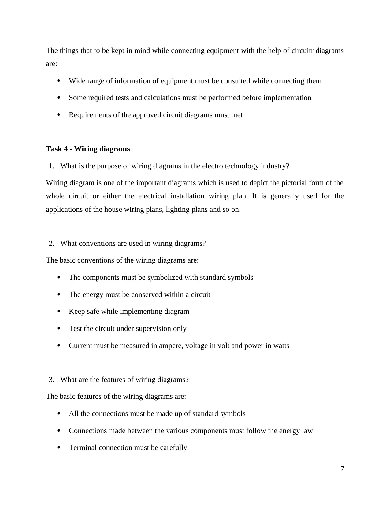
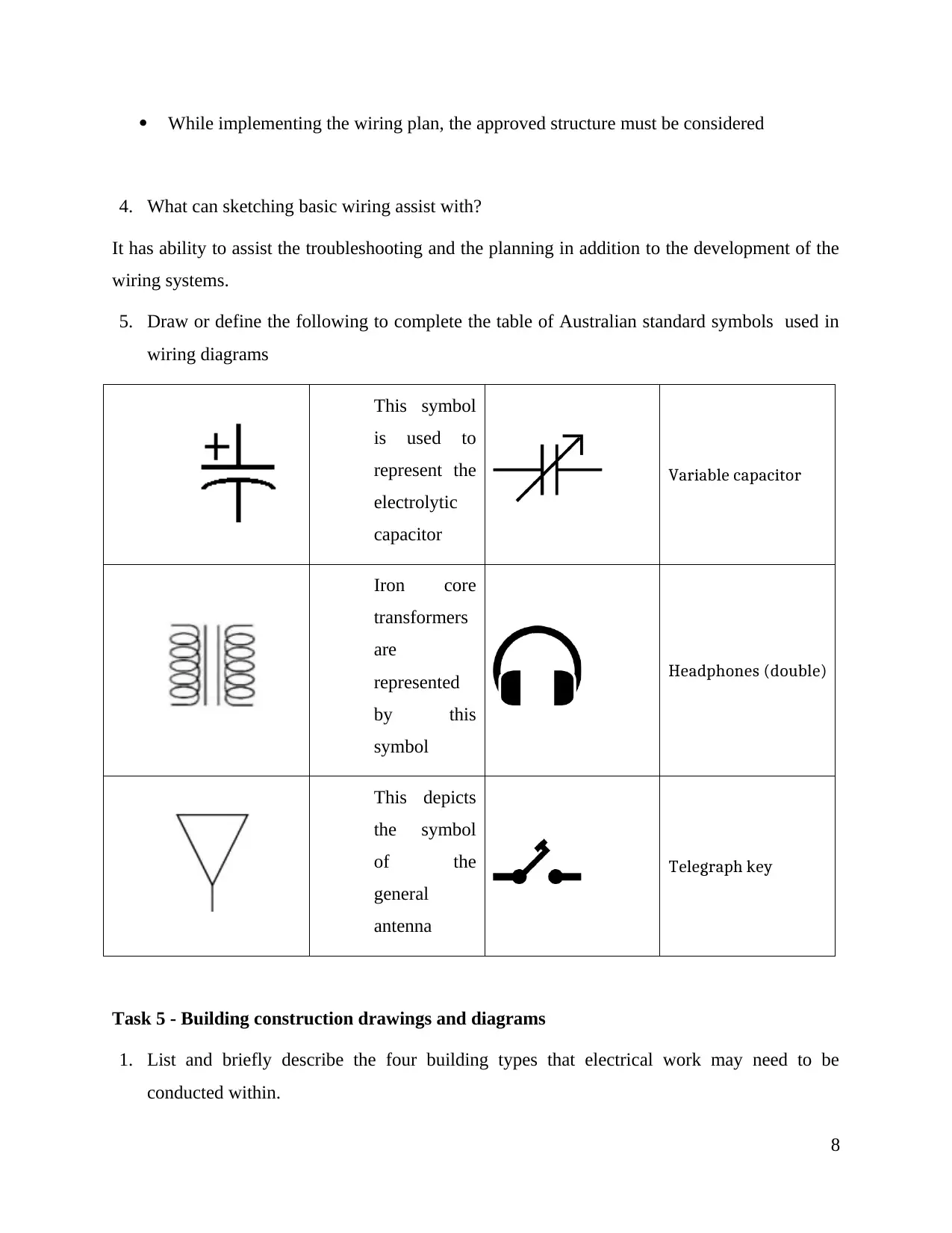
5. Draw or define the following to complete the table of Australian standard symbols used in
wiring diagrams
This symbol
is used to
represent the
electrolytic
capacitor
Variable capacitor
Iron core
transformers
are
represented
by this
symbol
Headphones (double)
This depicts
the symbol
of the
general
antenna
Telegraph key
Task 5 - Building construction drawings and diagrams
1. List and briefly describe the four building types that electrical work may need to be
conducted within.
8
4. What can sketching basic wiring assist with?
It has ability to assist the troubleshooting and the planning in addition to the development of the
wiring systems.
5. Draw or define the following to complete the table of Australian standard symbols used in
wiring diagrams
This symbol
is used to
represent the
electrolytic
capacitor
Variable capacitor
Iron core
transformers
are
represented
by this
symbol
Headphones (double)
This depicts
the symbol
of the
general
antenna
Telegraph key
Task 5 - Building construction drawings and diagrams
1. List and briefly describe the four building types that electrical work may need to be
conducted within.
8
⊘ This is a preview!⊘
Do you want full access?
Subscribe today to unlock all pages.
Trusted by 1+ million students worldwide
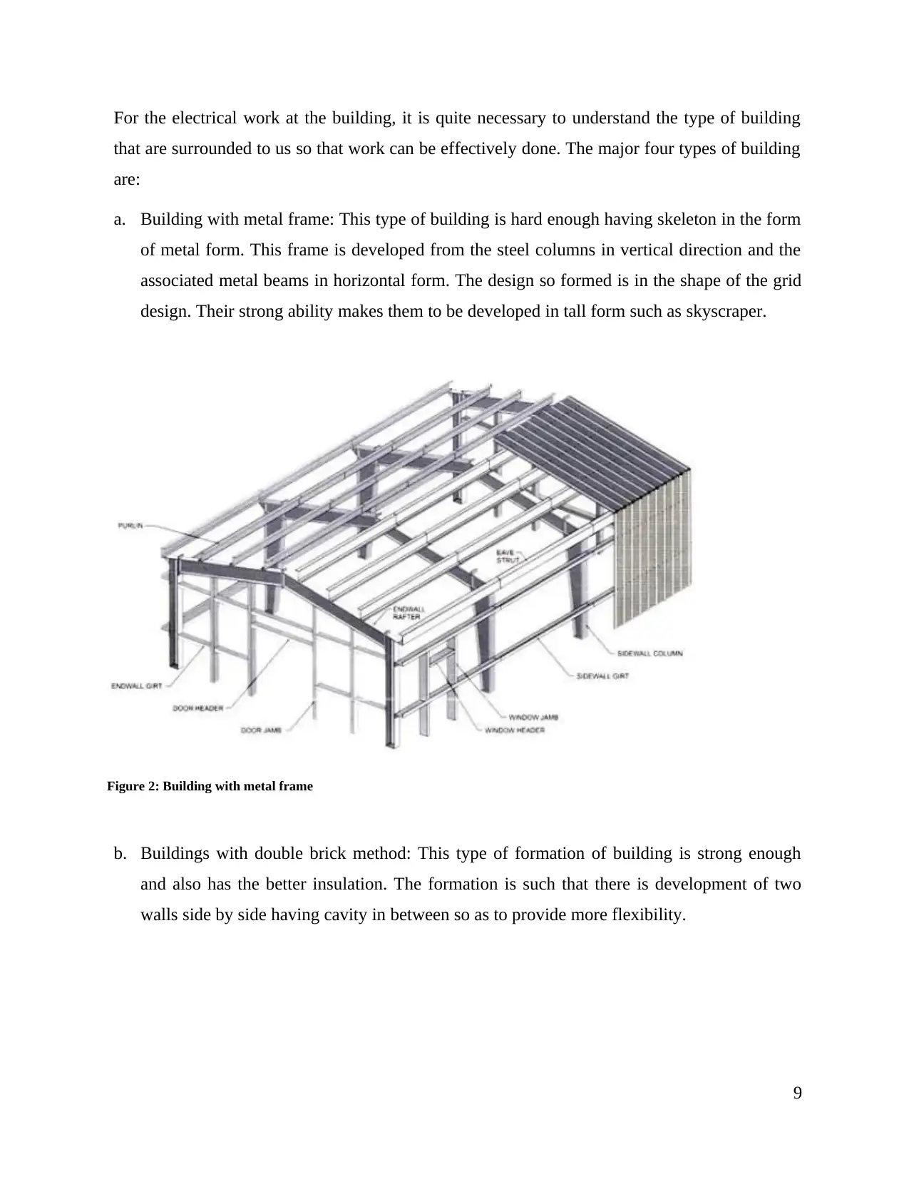
For the electrical work at the building, it is quite necessary to understand the type of building
that are surrounded to us so that work can be effectively done. The major four types of building
are:
a. Building with metal frame: This type of building is hard enough having skeleton in the form
of metal form. This frame is developed from the steel columns in vertical direction and the
associated metal beams in horizontal form. The design so formed is in the shape of the grid
design. Their strong ability makes them to be developed in tall form such as skyscraper.
Figure 2: Building with metal frame
b. Buildings with double brick method: This type of formation of building is strong enough
and also has the better insulation. The formation is such that there is development of two
walls side by side having cavity in between so as to provide more flexibility.
9
Paraphrase This Document
Need a fresh take? Get an instant paraphrase of this document with our AI Paraphraser
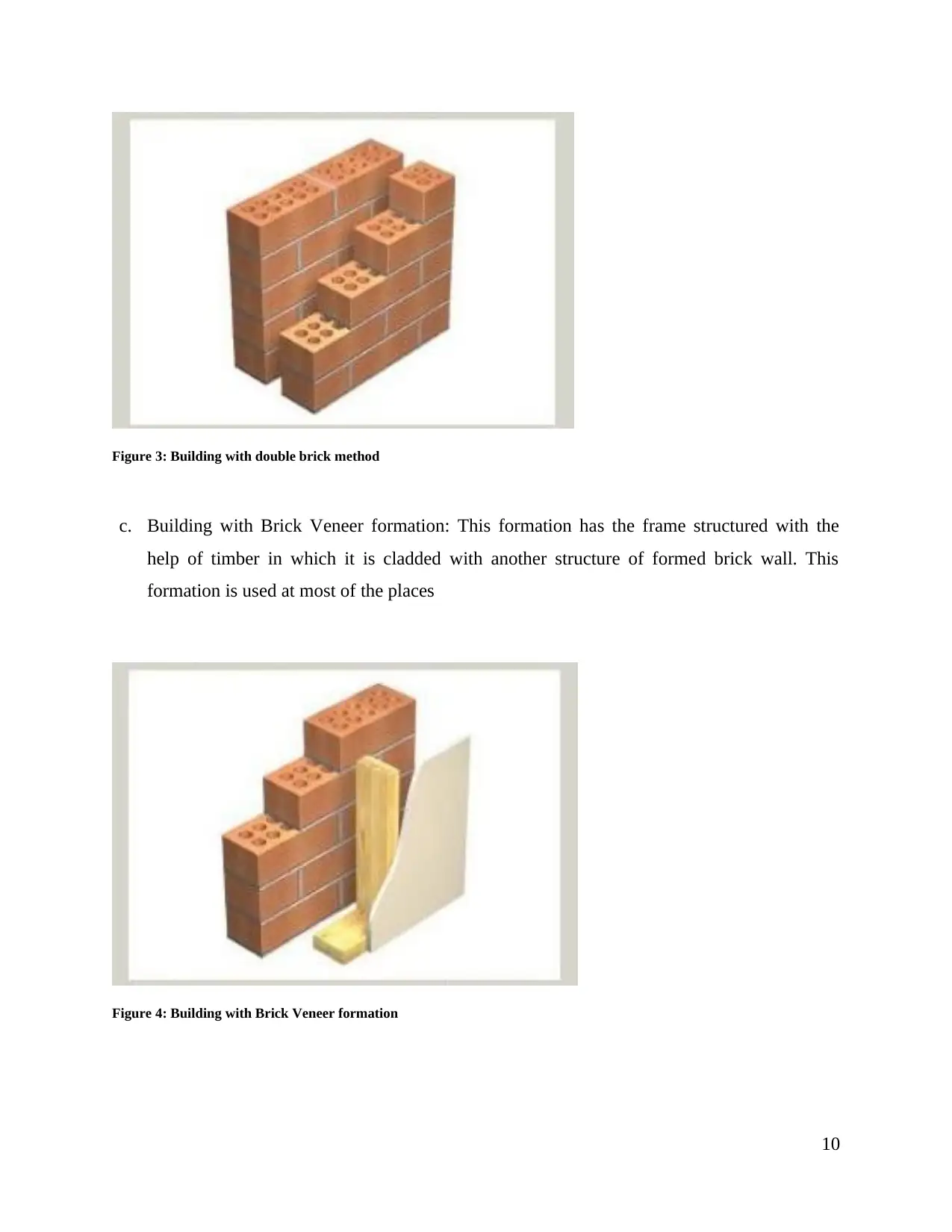
Figure 3: Building with double brick method
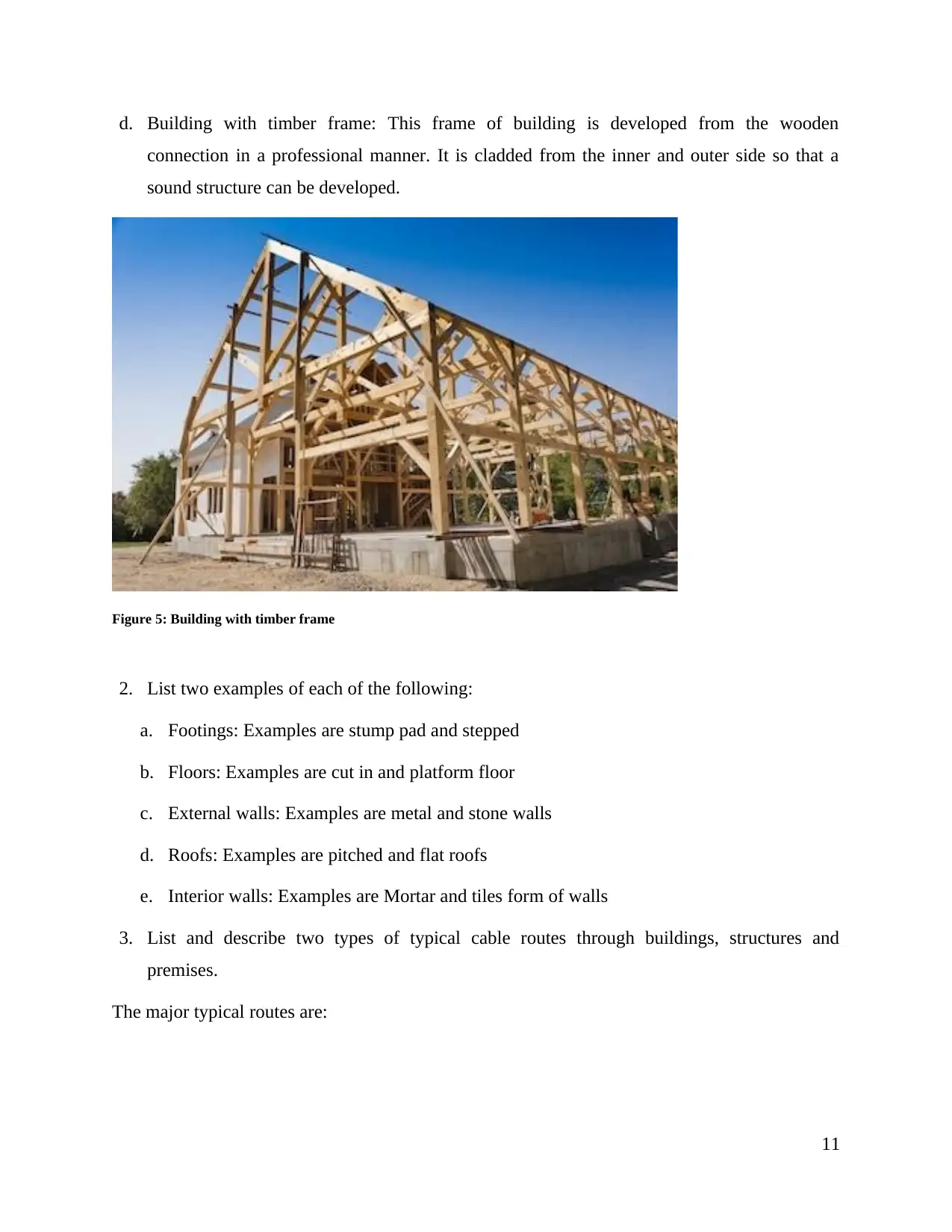
c. Building with Brick Veneer formation: This formation has the frame structured with the
help of timber in which it is cladded with another structure of formed brick wall. This
formation is used at most of the places
Figure 4: Building with Brick Veneer formation
10
c. Building with Brick Veneer formation: This formation has the frame structured with the
help of timber in which it is cladded with another structure of formed brick wall. This
formation is used at most of the places
Figure 4: Building with Brick Veneer formation
10
d. Building with timber frame: This frame of building is developed from the wooden
connection in a professional manner. It is cladded from the inner and outer side so that a
sound structure can be developed.
Figure 5: Building with timber frame
2. List two examples of each of the following:
a. Footings: Examples are stump pad and stepped
b. Floors: Examples are cut in and platform floor
c. External walls: Examples are metal and stone walls
d. Roofs: Examples are pitched and flat roofs
e. Interior walls: Examples are Mortar and tiles form of walls
3. List and describe two types of typical cable routes through buildings, structures and
premises.
The major typical routes are:
11
⊘ This is a preview!⊘
Do you want full access?
Subscribe today to unlock all pages.
Trusted by 1+ million students worldwide
1 out of 27
Related Documents


Your All-in-One AI-Powered Toolkit for Academic Success.
+13062052269
info@desklib.com
Available 24*7 on WhatsApp / Email
![[object Object]](/_next/static/media/star-bottom.7253800d.svg)
Unlock your academic potential
Copyright © 2020–2025 A2Z Services. All Rights Reserved. Developed and managed by ZUCOL.