Electrical and Electronic Control Assignment - Solution and Analysis
VerifiedAdded on 2020/02/19
|16
|978
|166
Homework Assignment
AI Summary
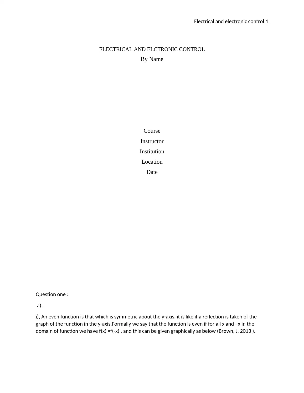
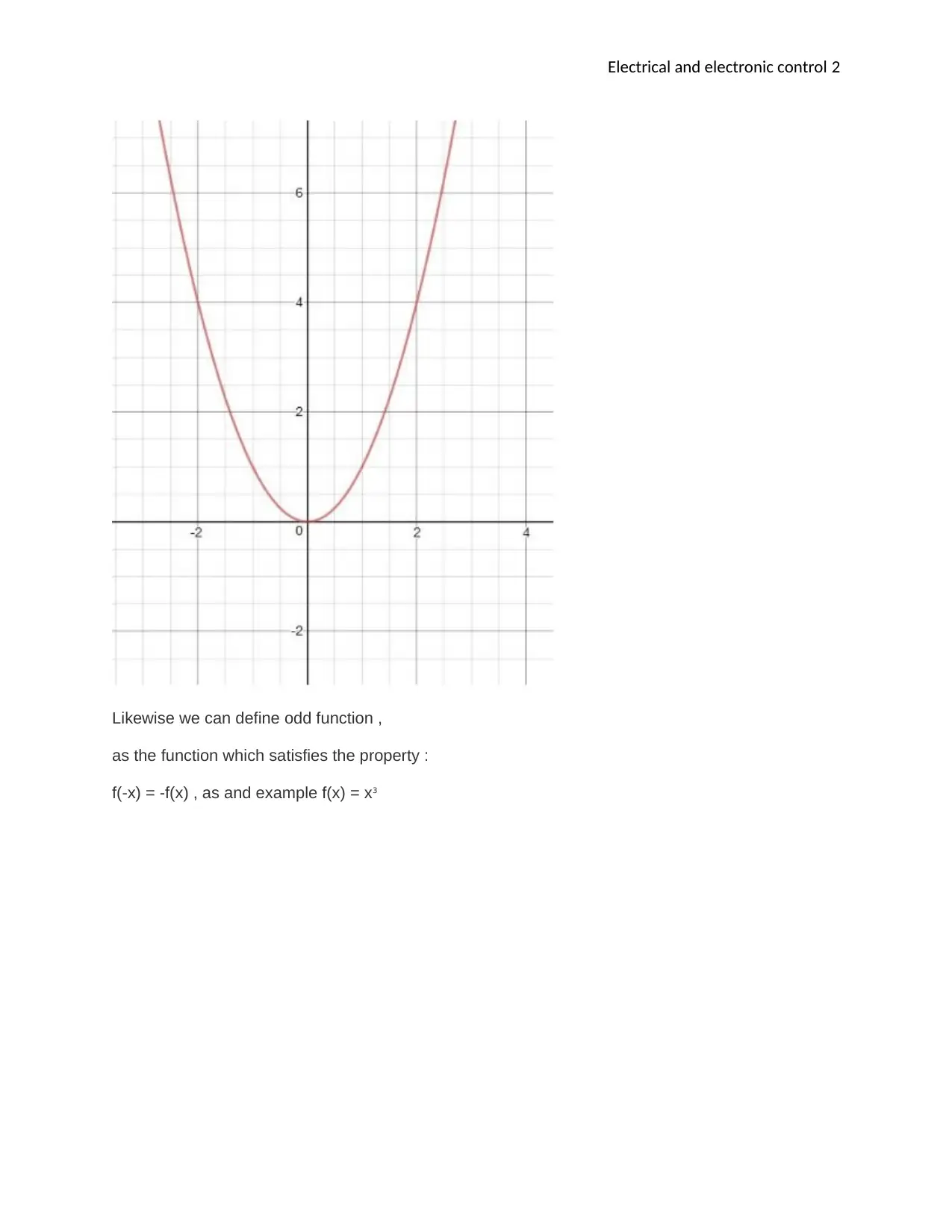
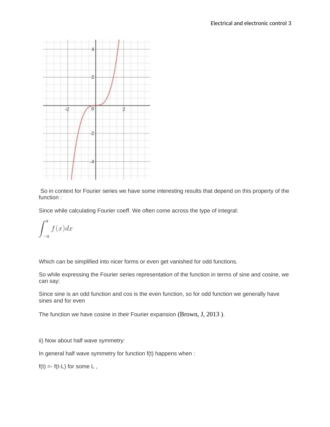
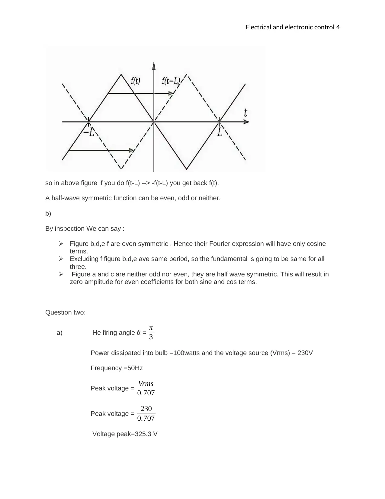
This document provides a comprehensive solution to an Electrical and Electronic Control assignment. The solution addresses several key concepts, including even and odd functions, half-wave symmetry, and their implications in Fourier series analysis. It delves into calculations of firing angles, power dissipation in electrical circuits, and the effects of asymmetrical waveforms, including harmonic analysis. The solution further explores Fourier transform analysis, identifying principal frequencies and calculating Total Harmonic Distortion (THD). The assignment also covers second-order system analysis, including the determination of damping ratios, natural frequencies, and phase angles. The document references key textbooks and resources to support the analysis and calculations, providing a complete and detailed solution to the assignment.

Electrical and electronic control 1
ELECTRICAL AND ELCTRONIC CONTROL
By Name
Course
Instructor
Institution
Location
Date
Question one :
a).
i), An even function is that which is symmetric about the y-axis, it is like if a reflection is taken of the
graph of the function in the y-axis.Formally we say that the function is even if for all x and –x in the
domain of function we have f(x) =f(-x) . and this can be given graphically as below (Brown, J, 2013 ).
Paraphrase This Document
Need a fresh take? Get an instant paraphrase of this document with our AI Paraphraser

Electrical and electronic control 2
Likewise we can define odd function ,
as the function which satisfies the property :
f(-x) = -f(x) , as and example f(x) = x3
Likewise we can define odd function ,
as the function which satisfies the property :
f(-x) = -f(x) , as and example f(x) = x3

Electrical and electronic control 3
So in context for Fourier series we have some interesting results that depend on this property of the
function :
Since while calculating Fourier coeff. We often come across the type of integral:
Which can be simplified into nicer forms or even get vanished for odd functions.
So while expressing the Fourier series representation of the function in terms of sine and cosine, we
can say:
Since sine is an odd function and cos is the even function, so for odd function we generally have
sines and for even
The function we have cosine in their Fourier expansion (Brown, J, 2013 ).
ii) Now about half wave symmetry:
In general half wave symmetry for function f(t) happens when :
f(t) =- f(t-L) for some L ,
⊘ This is a preview!⊘
Do you want full access?
Subscribe today to unlock all pages.

Trusted by 1+ million students worldwide

Electrical and electronic control 4
so in above figure if you do f(t-L) --> -f(t-L) you get back f(t).
A half-wave symmetric function can be even, odd or neither.
b)
By inspection We can say :
Figure b,d,e,f are even symmetric . Hence their Fourier expression will have only cosine
terms.
Excluding f figure b,d,e ave same period, so the fundamental is going to be same for all
three.
Figure a and c are neither odd nor even, they are half wave symmetric. This will result in
zero amplitude for even coefficients for both sine and cos terms.
Question two:
a) He firing angle ά = π
3
Power dissipated into bulb =100watts and the voltage source (Vrms) = 230V
Frequency =50Hz
Peak voltage = Vrms
0.707
Peak voltage = 230
0.707
Voltage peak=325.3 V
Paraphrase This Document
Need a fresh take? Get an instant paraphrase of this document with our AI Paraphraser

Electrical and electronic control 5
In order to obtain the power dissipated estimation in the bulb, we use the following
equations
VLoad = 325 ×
√ 2 π −( 2 π
3 )+
sin ( 2 π
3 )
4 π
Vload =206 V
100W = 230 × I
But I = 100/230 I = 0.43A
Power dissipated = 206 × 0.43
Power dissipated= 88.6 Watts
b)
The above figure illustrates that an asymmetrical waveform of the controlled sanctification of some,
from the above figure waveform we can clearly say that in asymmetrical waveform because the
waveform in the positive cycle and negative cycles are not the same (Brown, J, 2013 ). This is
because of firing triggering pulse switching to conduct the SCR we have to give some triggering
pulse in switching of the cycle I.e it is continuous for every cycle of positive and negative. Due to the
asymmetrical waveform, the circuit contains harmonics. These harmonics are shown in the figure
below.

Electrical and electronic control 6
c) For the below equations
we can draw the waveform as given below;
Explanation;
From the Fourier series, we can easily say that there is no conduction during the period of 0 to
π
2
π
2 π: There is nothing but waveform coil conduction from the Fourier series and we know
that the conduction starts from π
2 and ends at π.
From π 3 π
2 Again there is no conduction at this period because as the Fourier series
there is 0 for π wt 3 π
2 and that is the only reason why there is no co9nduction at
those points.
3 π
2 2π The Vm sin w(t) is reset so there is no conduction during the period of 3 π
2 to the
period of 2π.
Question 3:
i). Using the values given in the spreadsheet, we can obtain a graph which expires with the increase in
frequency. This clearly shows the Fourier transform analysis (John, R).
⊘ This is a preview!⊘
Do you want full access?
Subscribe today to unlock all pages.

Trusted by 1+ million students worldwide

Electrical and electronic control 7
ii. From the above diagram, we can clearly identify the principle frequency to be about 250 Hz. The
principle frequency is obtained from the above full wave by ( 0+500)/ 2 = 250 Hz
iii). For I1 rms I have
= √15.8+6.25+8.77 = 5.55A
by using this formula we can find,
Through employing the spreadsheet, it is possible to obtain the summation of the (In)2 by using the
mathematical formulas as in the spreadsheet, and the result of the summation is shown below
(John, R, 2012);
Paraphrase This Document
Need a fresh take? Get an instant paraphrase of this document with our AI Paraphraser

Electrical and electronic control 8
The summation is obtained as 826 693.1147
THD = 1
5.551 √ 826693.1147 × 100
THD= 0.1801×909.22×100
THD = 16.375 %
iv.
The summation is obtained as 826 693.1147
THD = 1
5.551 √ 826693.1147 × 100
THD= 0.1801×909.22×100
THD = 16.375 %
iv.

Electrical and electronic control 9
Question 4:
From the standard second order form of Characteristic equation (Brown, J, 2013 ).
a).
ƹ= ½ , w0=103 rad/sec
cos Փ= ƹ= ½
= 60Փ 0
- ½ × 103 + j √ 1− 1
4
-500 + j √3 × 500
Question 4:
From the standard second order form of Characteristic equation (Brown, J, 2013 ).
a).
ƹ= ½ , w0=103 rad/sec
cos Փ= ƹ= ½
= 60Փ 0
- ½ × 103 + j √ 1− 1
4
-500 + j √3 × 500
⊘ This is a preview!⊘
Do you want full access?
Subscribe today to unlock all pages.

Trusted by 1+ million students worldwide

Electrical and electronic control 10
b) ƹ=0.2, Wo=2×10³ rad/sec
-0.2×2×103 + j2×103 √ 1−0.2 ⌃2
-400 + j1959.59
= 78.46Փ 0
c).
ƹ= 2, Wo=2×10³ rad/sec
b) ƹ=0.2, Wo=2×10³ rad/sec
-0.2×2×103 + j2×103 √ 1−0.2 ⌃2
-400 + j1959.59
= 78.46Փ 0
c).
ƹ= 2, Wo=2×10³ rad/sec
Paraphrase This Document
Need a fresh take? Get an instant paraphrase of this document with our AI Paraphraser

Electrical and electronic control 11
Question 5:
Question 5:

Electrical and electronic control 12
Question 6:
Question 6:
⊘ This is a preview!⊘
Do you want full access?
Subscribe today to unlock all pages.

Trusted by 1+ million students worldwide
1 out of 16
Related Documents

Your All-in-One AI-Powered Toolkit for Academic Success.
+13062052269
info@desklib.com
Available 24*7 on WhatsApp / Email
Unlock your academic potential
Copyright © 2020–2025 A2Z Services. All Rights Reserved. Developed and managed by ZUCOL.