Electrical Energy Assignment Solution: ELEC3105, T2 2019
VerifiedAdded on 2022/10/12
|12
|1717
|373
Homework Assignment
AI Summary
This assignment solution for ELEC3105, Electrical Energy, delves into the analysis of AC machines and their magnetic circuits. It begins with an exploration of ferromagnetic materials and their B-H curves, emphasizing the importance of selecting an appropriate field current for synchronous machine design. The solution calculates operating points, flux density, and relative permeability. The assignment further investigates the magnetic circuit's reluctance, MMF, and the calculation of air gap flux density. It extends to the analysis of magnetic energy stored in the air gap, deriving equations for torque and inductance. Finally, the solution concludes with a detailed examination of energy stored in the air gap, inductance, and torque equations for the AC machine. The assignment covers key concepts like MMF, flux density, B-H curves, and the energy stored in the air gap, supported by derivations and graphical analysis.
Assignment, T2, 2019 ELEC 3105
ELEC 3105: Electrical Energy
ASSIGNMENT: T2, 2019
Solution to Question 1
Following inputs are provided,
Air gap length lg =2.5 mm
Number of Poles P = 2
Cross sectional area of the air gap Ag=500 c m2
Effective diameter of the rotor Dr =20 cm
Axial length h=60 cm
Mean length of stator flux path per pole lc ,stator =100 cm
Cross-sectional area seen by the flux in the core ¿ 450 c m2
Effective number of turns of the field coils Nf =500
Section (a)
Electrical machines are made of ferromagnetic materials. Ferromagnetic materials have nonlinear
material characteristics. Hence it is crucial to design the synchronous machine with appropriate field
current. The magnetic characteristic of the ferromagnetic material is represented in figure 1, which is a
plot of flux density versus field intensity.
The B-H curve has three regions, the first region can be categorized as linear region as the flux density
increases linearly with the flux intensity. The last part of the curve can be categorized as saturation region
as even large increase in the magnetic field does not cause any considerable increase in flux density. This
tells us that the relative permeability of the ferromagnetic material is not linear and changes with the
excitation current. The middle portion where the curve starts to bend can be described as knee point of the
curve.
The machine with great flux density can be designed by selecting the operating point very close to Knee
Point of the magnetizing curve.
The machines are operated at knee point considering the fact that at this point flux density of the
ferromagnetic material is more, thus resulting in lesser cross section of the material for construction of
machine.
1
Paraphrase This Document
Need a fresh take? Get an instant paraphrase of this document with our AI Paraphraser
Assignment, T2, 2019 ELEC 3105
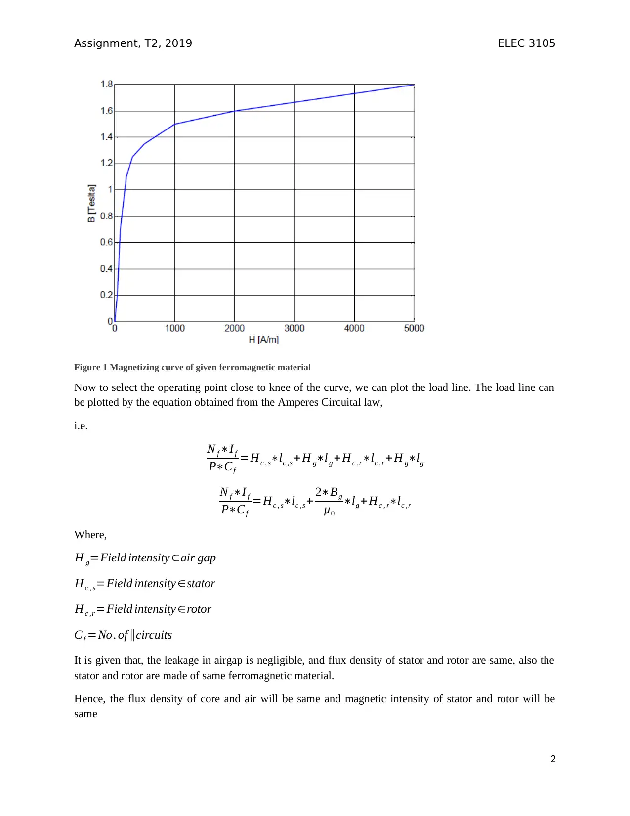
Figure 1 Magnetizing curve of given ferromagnetic material
Now to select the operating point close to knee of the curve, we can plot the load line. The load line can
be plotted by the equation obtained from the Amperes Circuital law,
i.e.
N f ∗I f
P∗Cf
=Hc , s∗lc ,s + H g∗lg +Hc ,r∗lc ,r +H g∗lg
N f ∗I f
P∗Cf
=Hc , s∗lc ,s + 2∗Bg
μ0
∗lg + Hc , r∗lc ,r
Where,
H g=Field intensity ∈air gap
Hc , s=Field intensity ∈stator
Hc ,r =Field intensity ∈rotor
Cf =No. of ∥circuits
It is given that, the leakage in airgap is negligible, and flux density of stator and rotor are same, also the
stator and rotor are made of same ferromagnetic material.
Hence, the flux density of core and air will be same and magnetic intensity of stator and rotor will be
same
2
Assignment, T2, 2019 ELEC 3105
N f ∗I f
P∗Cf
=Hc∗( lc, s +lc ,r ) + 2∗Bc
μ0
∗lg
Bc= μ0
2lg [ Nf ∗I f
P∗Cf
−Hc∗( lc, s +lc ,r ) ]
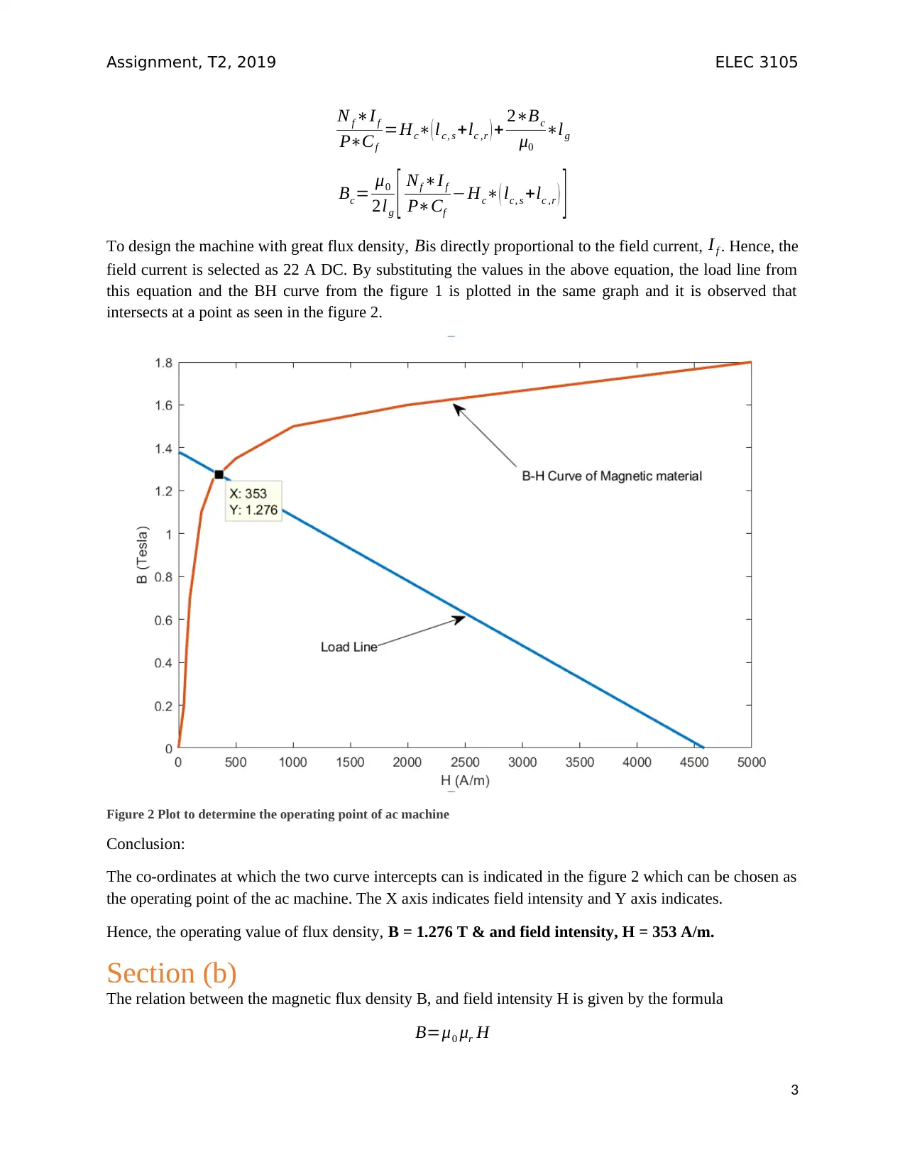
To design the machine with great flux density, Bis directly proportional to the field current, I f . Hence, the
field current is selected as 22 A DC. By substituting the values in the above equation, the load line from
this equation and the BH curve from the figure 1 is plotted in the same graph and it is observed that
intersects at a point as seen in the figure 2.
Figure 2 Plot to determine the operating point of ac machine
Conclusion:
The co-ordinates at which the two curve intercepts can is indicated in the figure 2 which can be chosen as
the operating point of the ac machine. The X axis indicates field intensity and Y axis indicates.
Hence, the operating value of flux density, B = 1.276 T & and field intensity, H = 353 A/m.
Section (b)
The relation between the magnetic flux density B, and field intensity H is given by the formula
B=μ0 μr H
3
N f ∗I f
P∗Cf
=Hc∗( lc, s +lc ,r ) + 2∗Bc
μ0
∗lg
Bc= μ0
2lg [ Nf ∗I f
P∗Cf
−Hc∗( lc, s +lc ,r ) ]
To design the machine with great flux density, Bis directly proportional to the field current, I f . Hence, the
field current is selected as 22 A DC. By substituting the values in the above equation, the load line from
this equation and the BH curve from the figure 1 is plotted in the same graph and it is observed that
intersects at a point as seen in the figure 2.
Figure 2 Plot to determine the operating point of ac machine
Conclusion:
The co-ordinates at which the two curve intercepts can is indicated in the figure 2 which can be chosen as
the operating point of the ac machine. The X axis indicates field intensity and Y axis indicates.
Hence, the operating value of flux density, B = 1.276 T & and field intensity, H = 353 A/m.
Section (b)
The relation between the magnetic flux density B, and field intensity H is given by the formula
B=μ0 μr H
3
⊘ This is a preview!⊘
Do you want full access?
Subscribe today to unlock all pages.
Trusted by 1+ million students worldwide
Assignment, T2, 2019 ELEC 3105
For the operating point selected in section (a),
B = 1.276 T; H = 353 A/m; μ0 =4 π∗10−7
Hence relative permeability can be calculated as
μr = 1.276
353∗4 π∗10−7 =2876.5
Section (c)
The magnetic circuit can be analyzed from the flux path of the ac machine.
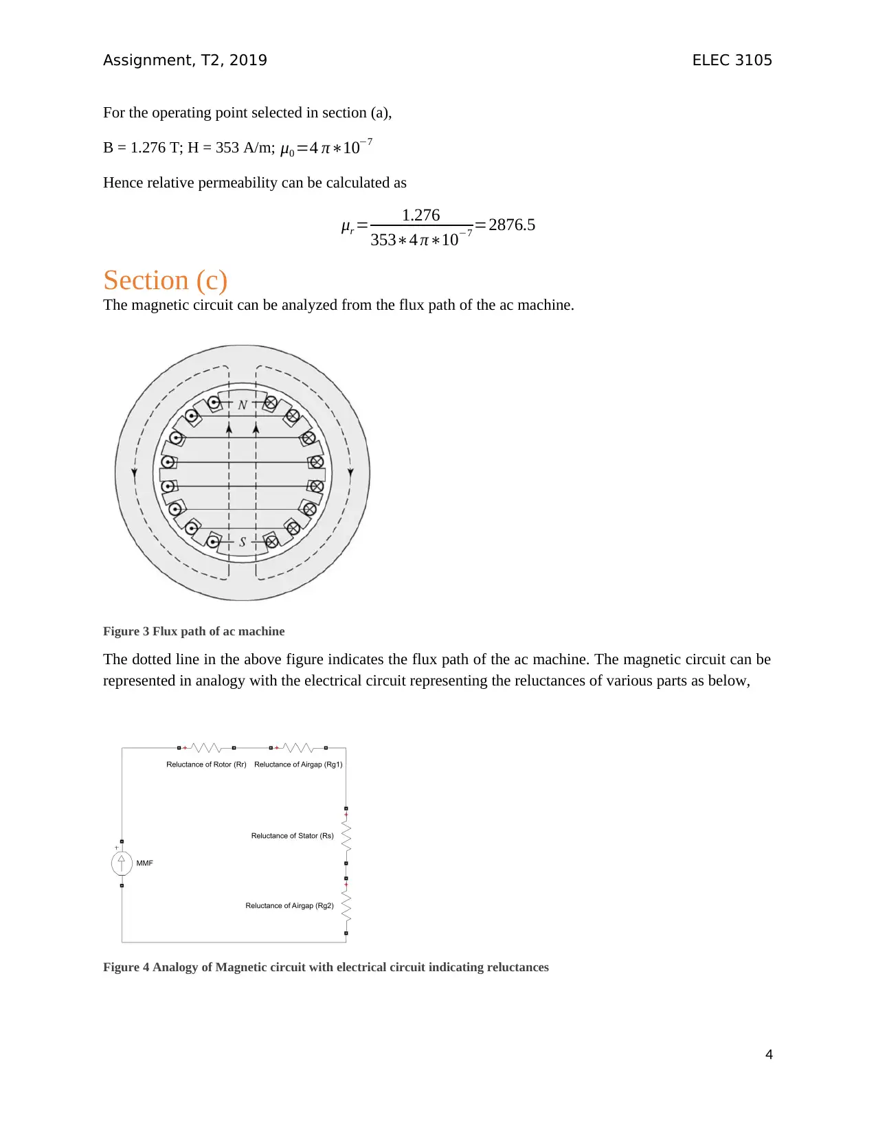
Figure 3 Flux path of ac machine
The dotted line in the above figure indicates the flux path of the ac machine. The magnetic circuit can be
represented in analogy with the electrical circuit representing the reluctances of various parts as below,
Figure 4 Analogy of Magnetic circuit with electrical circuit indicating reluctances
4
For the operating point selected in section (a),
B = 1.276 T; H = 353 A/m; μ0 =4 π∗10−7
Hence relative permeability can be calculated as
μr = 1.276
353∗4 π∗10−7 =2876.5
Section (c)
The magnetic circuit can be analyzed from the flux path of the ac machine.
Figure 3 Flux path of ac machine
The dotted line in the above figure indicates the flux path of the ac machine. The magnetic circuit can be
represented in analogy with the electrical circuit representing the reluctances of various parts as below,
Figure 4 Analogy of Magnetic circuit with electrical circuit indicating reluctances
4
Paraphrase This Document
Need a fresh take? Get an instant paraphrase of this document with our AI Paraphraser
Assignment, T2, 2019 ELEC 3105
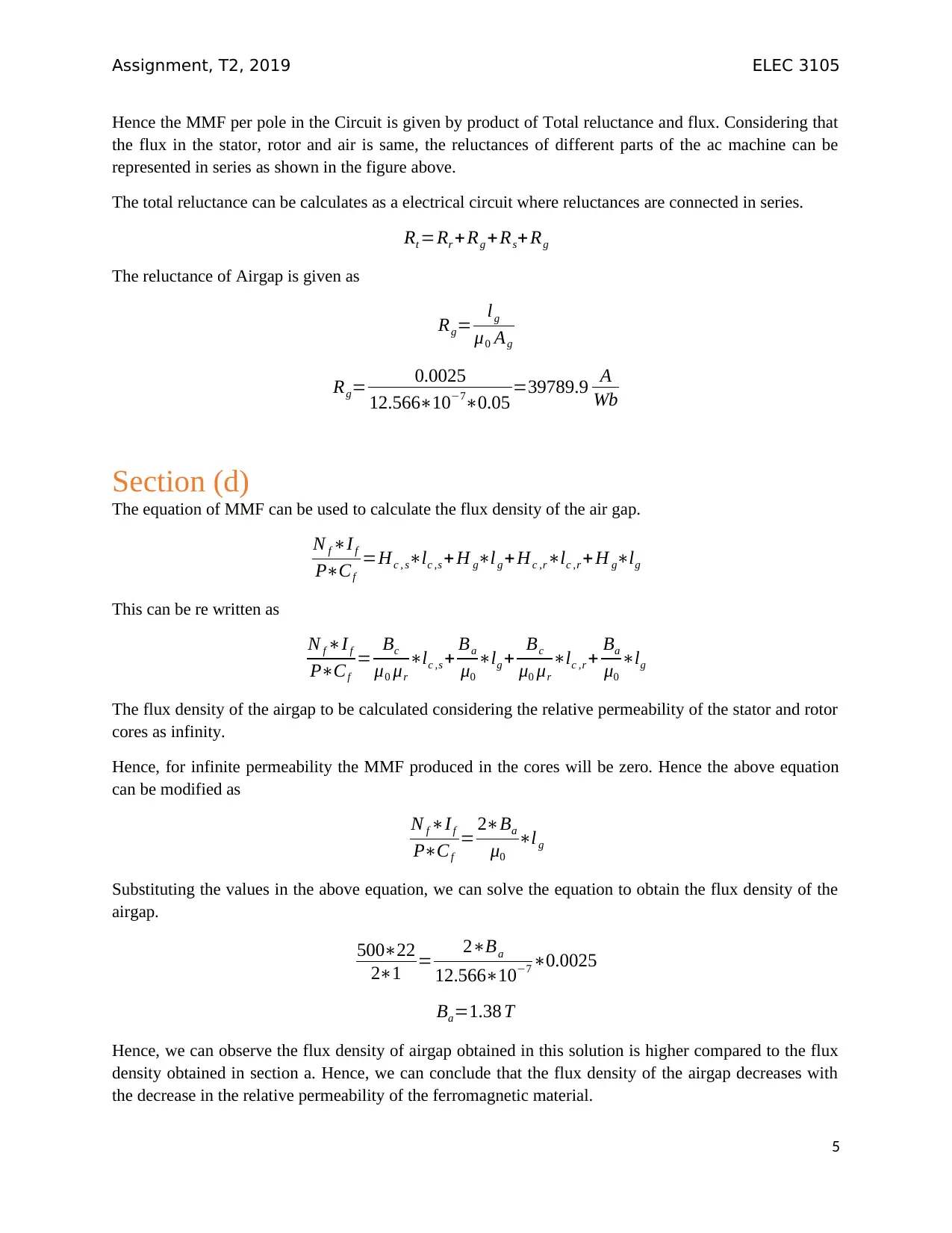
Hence the MMF per pole in the Circuit is given by product of Total reluctance and flux. Considering that
the flux in the stator, rotor and air is same, the reluctances of different parts of the ac machine can be
represented in series as shown in the figure above.
The total reluctance can be calculates as a electrical circuit where reluctances are connected in series.
Rt =Rr +Rg + Rs+ Rg
The reluctance of Airgap is given as
Rg= lg
μ0 Ag
Rg= 0.0025
12.566∗10−7∗0.05 =39789.9 A
Wb
Section (d)
The equation of MMF can be used to calculate the flux density of the air gap.
N f ∗I f
P∗Cf
=Hc , s∗lc ,s + H g∗lg +Hc ,r∗lc ,r +H g∗lg
This can be re written as
N f ∗If
P∗Cf
= Bc
μ0 μr
∗lc ,s + Ba
μ0
∗lg + Bc
μ0 μr
∗lc ,r + Ba
μ0
∗lg
The flux density of the airgap to be calculated considering the relative permeability of the stator and rotor
cores as infinity.
Hence, for infinite permeability the MMF produced in the cores will be zero. Hence the above equation
can be modified as
N f ∗If
P∗Cf
= 2∗Ba
μ0
∗l g
Substituting the values in the above equation, we can solve the equation to obtain the flux density of the
airgap.
500∗22
2∗1 = 2∗Ba
12.566∗10−7 ∗0.0025
Ba=1.38 T
Hence, we can observe the flux density of airgap obtained in this solution is higher compared to the flux
density obtained in section a. Hence, we can conclude that the flux density of the airgap decreases with
the decrease in the relative permeability of the ferromagnetic material.
5
Assignment, T2, 2019 ELEC 3105
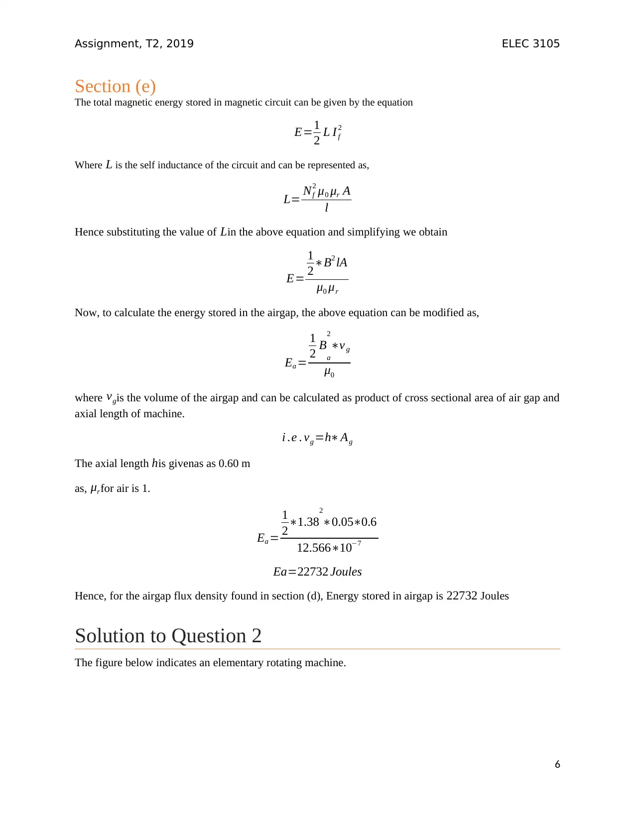
Section (e)
The total magnetic energy stored in magnetic circuit can be given by the equation
E=1
2 L I f
2
Where L is the self inductance of the circuit and can be represented as,
L= Nf
2 μ0 μr A
l
Hence substituting the value of Lin the above equation and simplifying we obtain
E=
1
2∗B2 lA
μ0 μr
Now, to calculate the energy stored in the airgap, the above equation can be modified as,
Ea =
1
2 Ba
2
∗v g
μ0
where vgis the volume of the airgap and can be calculated as product of cross sectional area of air gap and
axial length of machine.
i .e . vg =h∗Ag
The axial length his givenas as 0.60 m
as, μrfor air is 1.
Ea =
1
2∗1.38
2
∗0.05∗0.6
12.566∗10−7
Ea=22732 Joules
Hence, for the airgap flux density found in section (d), Energy stored in airgap is 22732 Joules
Solution to Question 2
The figure below indicates an elementary rotating machine.
6
⊘ This is a preview!⊘
Do you want full access?
Subscribe today to unlock all pages.
Trusted by 1+ million students worldwide
Assignment, T2, 2019 ELEC 3105
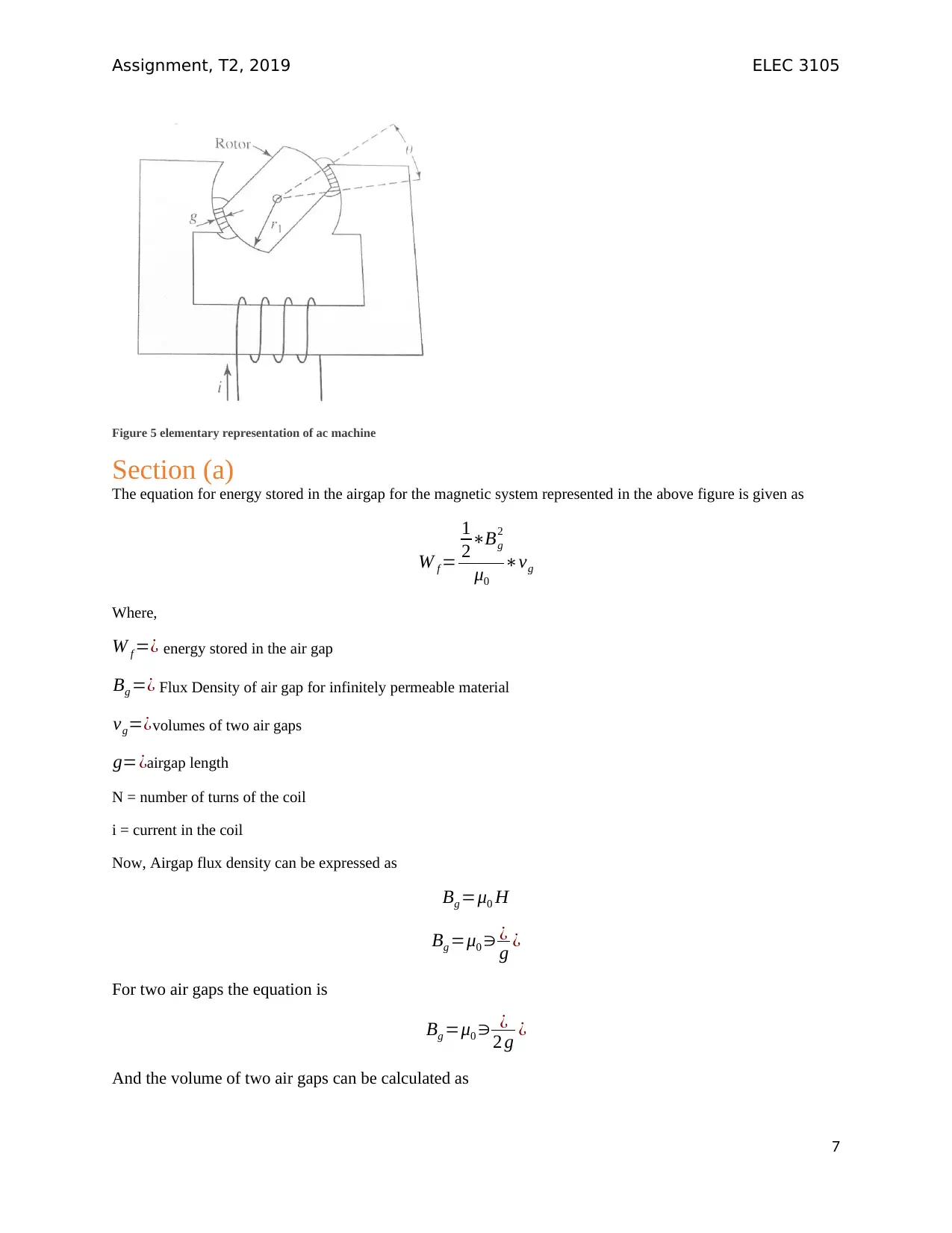
Figure 5 elementary representation of ac machine
Section (a)
The equation for energy stored in the airgap for the magnetic system represented in the above figure is given as
W f =
1
2∗Bg
2
μ0
∗vg
Where,
W f =¿ energy stored in the air gap
Bg =¿ Flux Density of air gap for infinitely permeable material
vg=¿volumes of two air gaps
g=¿airgap length
N = number of turns of the coil
i = current in the coil
Now, Airgap flux density can be expressed as
Bg =μ0 H
Bg =μ0 ∋ ¿
g ¿
For two air gaps the equation is
Bg =μ0 ∋ ¿
2 g ¿
And the volume of two air gaps can be calculated as
7
Paraphrase This Document
Need a fresh take? Get an instant paraphrase of this document with our AI Paraphraser
Assignment, T2, 2019 ELEC 3105
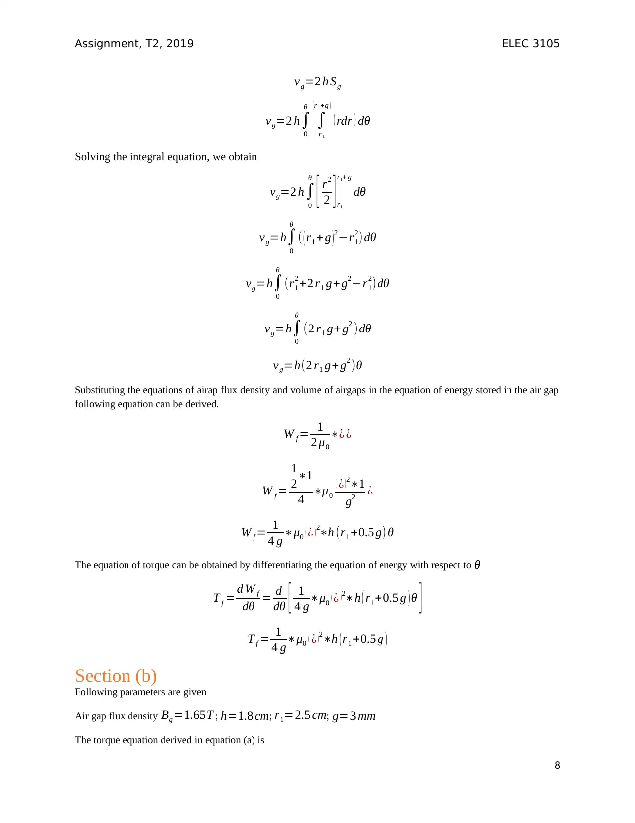
vg=2 h Sg
vg=2 h∫
0
θ
∫
r 1
( r 1+g )
( rdr ) dθ
Solving the integral equation, we obtain
vg=2 h∫
0
θ
[ r2
2 ] r1
r1+ g
dθ
vg=h∫
0
θ
( ( r1 + g )2−r1
2) dθ
vg=h∫
0
θ
(r1
2 +2 r1 g+g2−r1
2)dθ
vg=h∫
0
θ
(2 r1 g+ g2 )dθ
vg=h(2 r1 g+ g2 )θ
Substituting the equations of airap flux density and volume of airgaps in the equation of energy stored in the air gap
following equation can be derived.
W f = 1
2 μ0
∗¿ ¿
W f =
1
2∗1
4 ∗μ0
( ¿ )2∗1
g2 ¿
W f = 1
4 g ∗μ0 ( ¿ ) 2∗h (r1 +0.5 g) θ
The equation of torque can be obtained by differentiating the equation of energy with respect to θ
T f = d W f
dθ = d
dθ [ 1
4 g∗μ0 ( ¿ ) 2∗h ( r1+ 0.5 g ) θ ]
T f = 1
4 g∗μ0 ( ¿ )2∗h ( r1 +0.5 g )
Section (b)
Following parameters are given
Air gap flux density Bg =1.65T ; h=1.8 cm; r1=2.5 cm; g=3 mm
The torque equation derived in equation (a) is
8
Assignment, T2, 2019 ELEC 3105
T f = 1
4 g∗μ0 ( ¿ )2∗h ( r1 +0.5 g )
From the equation of flux density, we have
Bg =μ0 ∋ ¿
2 g ¿
i.e.
¿=2 Bg∗g
μ0
Substituting value of ¿in the torque equation we obtain,
T f = 1
4 g∗μ0 ( 2 Bg∗g
μ0 )
2
∗h ( r 1+0.5 g )
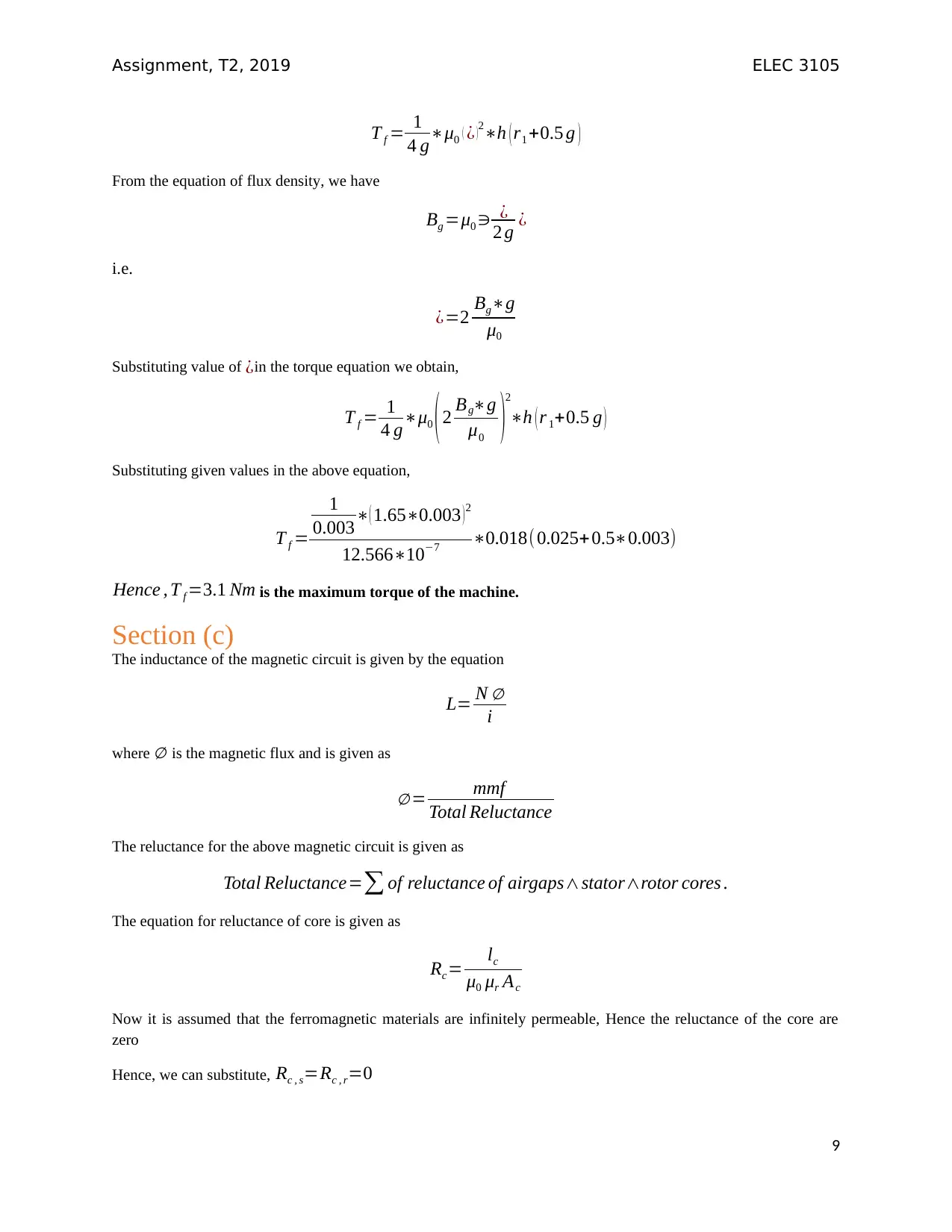
Substituting given values in the above equation,
T f =
1
0.003∗( 1.65∗0.003 ) 2
12.566∗10−7 ∗0.018( 0.025+0.5∗0.003)
Hence , T f =3.1 Nm is the maximum torque of the machine.
Section (c)
The inductance of the magnetic circuit is given by the equation
L= N ∅
i
where ∅ is the magnetic flux and is given as
∅ = mmf
Total Reluctance
The reluctance for the above magnetic circuit is given as
Total Reluctance=∑ of reluctance of airgaps∧stator∧rotor cores .
The equation for reluctance of core is given as
Rc= lc
μ0 μr Ac
Now it is assumed that the ferromagnetic materials are infinitely permeable, Hence the reluctance of the core are
zero
Hence, we can substitute, Rc , s=Rc , r=0
9
T f = 1
4 g∗μ0 ( ¿ )2∗h ( r1 +0.5 g )
From the equation of flux density, we have
Bg =μ0 ∋ ¿
2 g ¿
i.e.
¿=2 Bg∗g
μ0
Substituting value of ¿in the torque equation we obtain,
T f = 1
4 g∗μ0 ( 2 Bg∗g
μ0 )
2
∗h ( r 1+0.5 g )
Substituting given values in the above equation,
T f =
1
0.003∗( 1.65∗0.003 ) 2
12.566∗10−7 ∗0.018( 0.025+0.5∗0.003)
Hence , T f =3.1 Nm is the maximum torque of the machine.
Section (c)
The inductance of the magnetic circuit is given by the equation
L= N ∅
i
where ∅ is the magnetic flux and is given as
∅ = mmf
Total Reluctance
The reluctance for the above magnetic circuit is given as
Total Reluctance=∑ of reluctance of airgaps∧stator∧rotor cores .
The equation for reluctance of core is given as
Rc= lc
μ0 μr Ac
Now it is assumed that the ferromagnetic materials are infinitely permeable, Hence the reluctance of the core are
zero
Hence, we can substitute, Rc , s=Rc , r=0
9
⊘ This is a preview!⊘
Do you want full access?
Subscribe today to unlock all pages.
Trusted by 1+ million students worldwide
Assignment, T2, 2019 ELEC 3105
Hence Total reluctance for two air gaps = 2 Rg
The Reluctance of the air gap is given by the equation
Rg= g
μ0 Ag
The MMF is given by the equation
mmf =¿
Substituting these equations in the equation of flux per pole,
∅ = ( ¿ )
2 g
μ0 Ag
∅ = ¿
2∗g μ0 Ag
Substituting this in the equation of inductance
L=
N
i ∗¿
2∗g μ0 Ag
L=μ0
N2
2 ∗Ag
g
By multiplying numerator and denominator by 2*g,
L=μ0
N2
2 ∗2∗g∗Ag
2∗g2
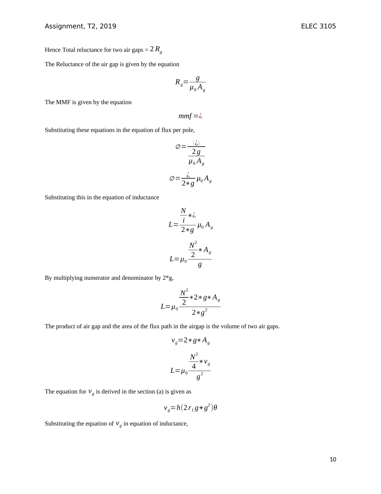
The product of air gap and the area of the flux path in the airgap is the volume of two air gaps.
vg=2∗g∗Ag
L=μ0
N2
4 ∗vg
g2
The equation for vg is derived in the section (a) is given as
vg=h(2 r1 g+ g2 )θ
Substituting the equation of vg in equation of inductance,
10
Hence Total reluctance for two air gaps = 2 Rg
The Reluctance of the air gap is given by the equation
Rg= g
μ0 Ag
The MMF is given by the equation
mmf =¿
Substituting these equations in the equation of flux per pole,
∅ = ( ¿ )
2 g
μ0 Ag
∅ = ¿
2∗g μ0 Ag
Substituting this in the equation of inductance
L=
N
i ∗¿
2∗g μ0 Ag
L=μ0
N2
2 ∗Ag
g
By multiplying numerator and denominator by 2*g,
L=μ0
N2
2 ∗2∗g∗Ag
2∗g2
The product of air gap and the area of the flux path in the airgap is the volume of two air gaps.
vg=2∗g∗Ag
L=μ0
N2
4 ∗vg
g2
The equation for vg is derived in the section (a) is given as
vg=h(2 r1 g+ g2 )θ
Substituting the equation of vg in equation of inductance,
10
Paraphrase This Document
Need a fresh take? Get an instant paraphrase of this document with our AI Paraphraser
Assignment, T2, 2019 ELEC 3105
L=μ0
N2
4 g2 h ( 2 r1 g+g2 ) θ
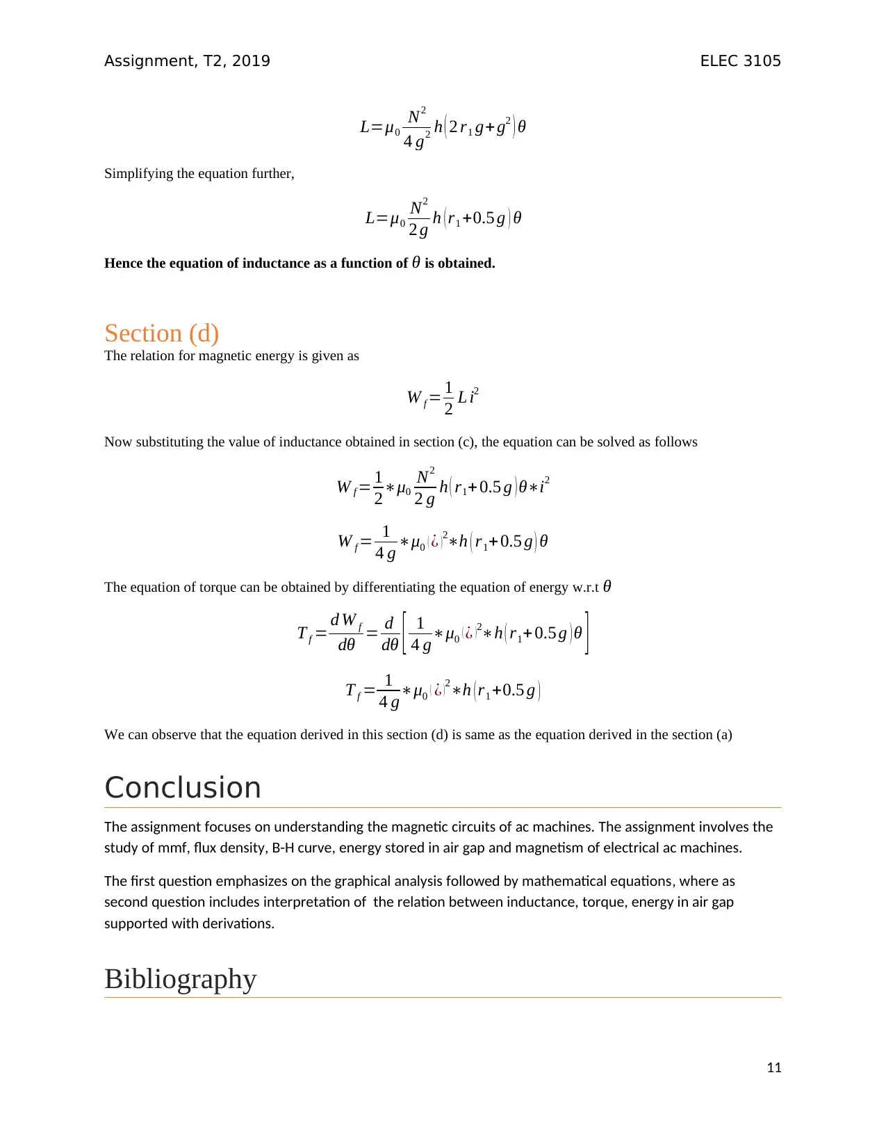
Simplifying the equation further,
L=μ0
N2
2 g h ( r1 +0.5 g ) θ
Hence the equation of inductance as a function of θ is obtained.
Section (d)
The relation for magnetic energy is given as
W f = 1
2 L i2
Now substituting the value of inductance obtained in section (c), the equation can be solved as follows
W f = 1
2∗μ0
N2
2 g h ( r1+ 0.5 g ) θ∗i2
W f = 1
4 g ∗μ0 ( ¿ )2∗h ( r1+0.5 g ) θ
The equation of torque can be obtained by differentiating the equation of energy w.r.t θ
T f = d W f
dθ = d
dθ [ 1
4 g∗μ0 ( ¿ ) 2∗h ( r1+ 0.5 g ) θ ]
T f = 1
4 g∗μ0 ( ¿ )2∗h ( r1 +0.5 g )
We can observe that the equation derived in this section (d) is same as the equation derived in the section (a)
Conclusion
The assignment focuses on understanding the magnetic circuits of ac machines. The assignment involves the
study of mmf, flux density, B-H curve, energy stored in air gap and magnetism of electrical ac machines.
The first question emphasizes on the graphical analysis followed by mathematical equations, where as
second question includes interpretation of the relation between inductance, torque, energy in air gap
supported with derivations.
Bibliography
11
L=μ0
N2
4 g2 h ( 2 r1 g+g2 ) θ
Simplifying the equation further,
L=μ0
N2
2 g h ( r1 +0.5 g ) θ
Hence the equation of inductance as a function of θ is obtained.
Section (d)
The relation for magnetic energy is given as
W f = 1
2 L i2
Now substituting the value of inductance obtained in section (c), the equation can be solved as follows
W f = 1
2∗μ0
N2
2 g h ( r1+ 0.5 g ) θ∗i2
W f = 1
4 g ∗μ0 ( ¿ )2∗h ( r1+0.5 g ) θ
The equation of torque can be obtained by differentiating the equation of energy w.r.t θ
T f = d W f
dθ = d
dθ [ 1
4 g∗μ0 ( ¿ ) 2∗h ( r1+ 0.5 g ) θ ]
T f = 1
4 g∗μ0 ( ¿ )2∗h ( r1 +0.5 g )
We can observe that the equation derived in this section (d) is same as the equation derived in the section (a)
Conclusion
The assignment focuses on understanding the magnetic circuits of ac machines. The assignment involves the
study of mmf, flux density, B-H curve, energy stored in air gap and magnetism of electrical ac machines.
The first question emphasizes on the graphical analysis followed by mathematical equations, where as
second question includes interpretation of the relation between inductance, torque, energy in air gap
supported with derivations.
Bibliography
11
Assignment, T2, 2019 ELEC 3105
[1] T. A. Lipo, “Electromagnetic Design of Synchronous Machines,” pp. 401–453, 2017.
[2] Z. Tian, C. Zhang, and S. Zhang, “Analytical Calculation of Magnetic Field Distribution and Stator Iron
Losses for Surface-Mounted Permanent Magnaduvula Konjam Pakkatha Kaanomnet Synchronous
Machines,” 2017.
[3] G. Heydt, S. Kalsi, and E. Kyriakides, “A Short Course on Synchronous Machines and Synchronous
Condensers,” 2003.
[4] T. A. Lipo, “The MMF and Field Distribution of an AC Winding,” pp. 51–77, 2017.
[5] A. K. Sawhney, “A course in Electrical Machine Design,” Chapter 4_118-177p.pdf. .
[6] A. K. Sawhney, “A course in Electrical Machine Design,” Chapter 12_722-803p.pdf. .
12
⊘ This is a preview!⊘
Do you want full access?
Subscribe today to unlock all pages.
Trusted by 1+ million students worldwide
1 out of 12

Your All-in-One AI-Powered Toolkit for Academic Success.
+13062052269
info@desklib.com
Available 24*7 on WhatsApp / Email
![[object Object]](/_next/static/media/star-bottom.7253800d.svg)
Unlock your academic potential
Copyright © 2020–2026 A2Z Services. All Rights Reserved. Developed and managed by ZUCOL.