Electrical Engineering - Antennas and Multiplexing Assignment 1
VerifiedAdded on 2020/03/04
|6
|1002
|233
Homework Assignment
AI Summary
This assignment solution delves into the realm of electrical engineering, specifically focusing on antennas and multiplexing techniques. The first section of the assignment examines different types of antennas, including directional antennas like Yagi and Horn antennas, as well as omnidirectional antennas. It discusses their characteristics, pros, cons, and potential future applications. The second section explores multiplexing techniques used in wireless networking, with a comparative analysis of Frequency Division Multiple Access (FDMA) and Code Division Multiple Access (CDMA). The assignment highlights the operational principles, advantages, and disadvantages of each technique, providing a comprehensive understanding of their roles in modern telecommunications. The solution references key sources to support the analysis.
Running head: ASSIGNMENT 1
Assignment
[Student Name Here]
[Institution’s Name Here]
[Professor’s Name Here]
[Date Here]
Assignment
[Student Name Here]
[Institution’s Name Here]
[Professor’s Name Here]
[Date Here]
Paraphrase This Document
Need a fresh take? Get an instant paraphrase of this document with our AI Paraphraser
ASSIGNMENT 1 2
Question 1
Antennas
Antennas are devices that transform radio frequency (RF) signals into electromagnetic waves.
These waves usually move through free space towards different conductors as facilitated by
their reciprocity characteristic i.e. they can be transmitted and received (Reckeweg, 2011).
Types of antennas
Antennas can be broadly categorised into three major groups: Omnidirectional, antennas that
propagate in all directions; semi-directional, antennas that are restricted or constricted in
certain fashions and therefore have specific operational angles and directional antennas which
propagate in one direction through the use of narrow beams.
Directional antenna: Yagi antennas – these antennas are mostly used in systems that require
high gains and directivity, for instance in television sets. Its design facilitates better levels of
signal to noise ratio (SNL) which focuses power in one region (Reckeweg, 2011).
Pros:
They have high gains which facilitate the transmission of low signals
Their high levels of directivity minimise signal interferences.
Simple and straightforward construction based on simple elements.
Finally, they are easy to use as their design is easy to mount.
Cons:
To accommodate high gain levels, the antennas must be long in size.
Yagi antennas are limited to small gains i.e. 20dB (radio-electronics, 2017).
ASSIGNMENT 1 3
Horn antenna – another common example of directional antennas, however, this antenna
consists of a flare-like aperture that focuses the beams in a given direction. Now, the energy
of the transferred beam is usually slowly transferred into a radiation which reduces the losses.
In the industry, this antenna is referred to as a ‘flared out wave guide’ as its design facilitates
higher directivity which reduces signal diffraction.
Pros:
Its propagation pattern consists of very few minor lobes (signal loss lobes).
It has a high impedance matching scheme.
Due to its shape and design, it has better directivity.
Moreover, it has narrower signal width.
Finally, it has minimal standing waves.
Cons:
Complex design (Reckeweg, 2011).
Cellular antennas – a good example of Omni-directional antennas which are commonly used
in mobile devices, from cell-phones to home appliances and even vehicles. They have the
benefit of receiving signals in all directions but with minimal signal strengths.
Pros:
They are easy to install.
Can amplify signals from multiple sources.
Good signal boosting capabilities.
Cons:
Minimal transmission distance.
Poor for low power signals (Carr, 2012)
⊘ This is a preview!⊘
Do you want full access?
Subscribe today to unlock all pages.

Trusted by 1+ million students worldwide
ASSIGNMENT 1 4
Future applications
Directional antennas such as Horn and Yagi will always have the transmission advantage to
their design that has better directivity properties. In fact, their application is only halted by
their size. On the other hand, omnidirectional antennas e.g. cellular antennas are limited in
terms of distance and directivity but are preferred in mobile systems due to their size. The
future will most defiantly combine the two resulting in smart antennas that will have the
flexibility of Omni-directional antennas but with the power of the directional antennas.
Question 2
Multiplexing techniques in wireless networking
To meet the demands made by customers, the telecommunication industry has tried to
develop efficient communication protocols that maximise the resources transferred. Now,
bandwidth as a communication resource has always been a major problem for
telecommunication which has led to the various variations highlighted below. In both
instances, multiplexing, a facility that enables the multiple access of signals is used.
Frequency Division Multiple Access (FDMA) a protocol that uses the frequency parameter to
assign channels for communication, through the same principle of multiple signal access. In
essence, a communication channel is defined by a frequency. Now, in wireless networking,
each communication channel is assigned a single user at any given time. On the other hand,
Code Division Multiple Access (CDMA), uses a unique pseudorandom number (binary
sequence) to regulate the transmission of multiple signals via a single carrier (channel).
Therefore, a unique encoding key is used for each signal and this key is used to separate the
signals at the destination (corps, 2000).
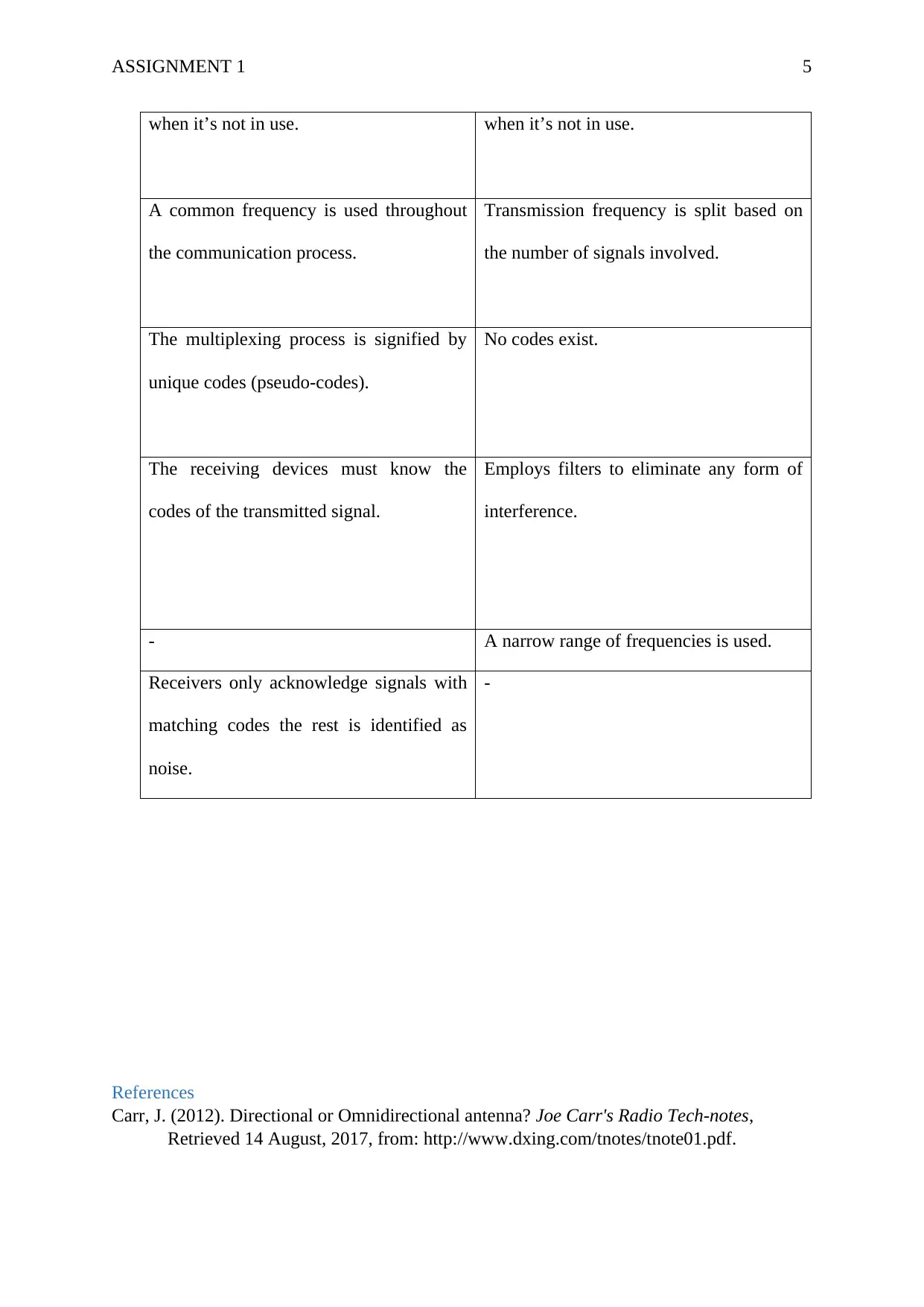
CDMA FDMA
The communication channel is closed The communication channel remains idle
Paraphrase This Document
Need a fresh take? Get an instant paraphrase of this document with our AI Paraphraser
ASSIGNMENT 1 5
when it’s not in use. when it’s not in use.
A common frequency is used throughout
the communication process.
Transmission frequency is split based on
the number of signals involved.
The multiplexing process is signified by
unique codes (pseudo-codes).
No codes exist.
The receiving devices must know the
codes of the transmitted signal.
Employs filters to eliminate any form of
interference.
- A narrow range of frequencies is used.
Receivers only acknowledge signals with
matching codes the rest is identified as
noise.
-
References
Carr, J. (2012). Directional or Omnidirectional antenna? Joe Carr's Radio Tech-notes,
Retrieved 14 August, 2017, from: http://www.dxing.com/tnotes/tnote01.pdf.

ASSIGNMENT 1 6
corps, W. a. (2000). FDMA vs. TDMA vs. CDMA. Connecting Wireless, Retrieved 14
August, 2017, from: http://wirelessapplications.com/pdf/lf/FD_TD_CDMA.pdf.
radio-electronics. (2017). Yagi Antenna / Yagi-Uda Antenna. Antennas and propagation,
Retrieved 14 August, 2017, from:
http://www.radio-electronics.com/info/antennas/yagi/yagi.php.
Reckeweg, M. (2011). Antenna basic. Rhode & Schwarz, Retrieved 14 August, 2017, from:
https://home.zhaw.ch/kunr/NTM1/literatur/Rhode_Schwarz_Antenna_Basics.pdf.
⊘ This is a preview!⊘
Do you want full access?
Subscribe today to unlock all pages.

Trusted by 1+ million students worldwide
1 out of 6
Related Documents
Your All-in-One AI-Powered Toolkit for Academic Success.
+13062052269
info@desklib.com
Available 24*7 on WhatsApp / Email
![[object Object]](/_next/static/media/star-bottom.7253800d.svg)
Unlock your academic potential
Copyright © 2020–2026 A2Z Services. All Rights Reserved. Developed and managed by ZUCOL.


