Electrical and Electronic Principles - BTEC DC Networks Assignment

Verified

Added on  2022/12/22

|12
|396
|49
Homework Assignment
AI Summary
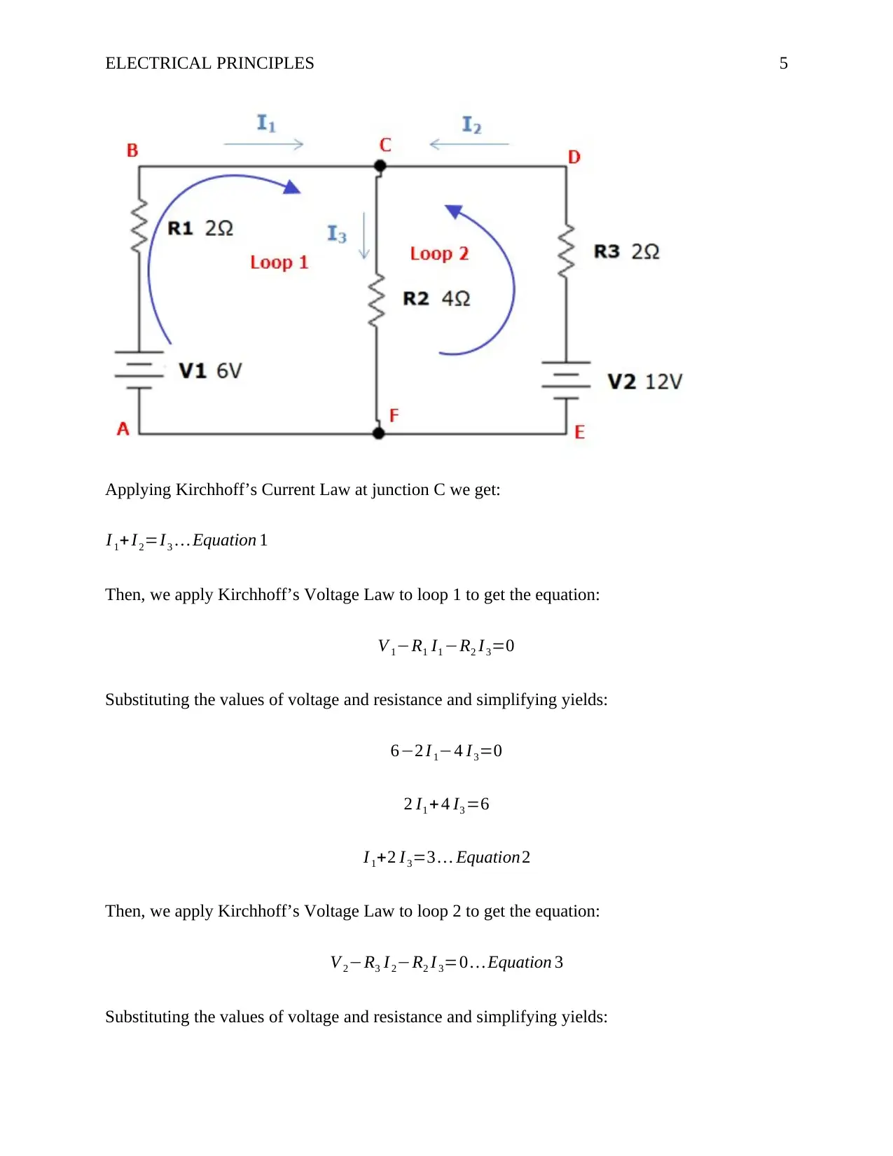
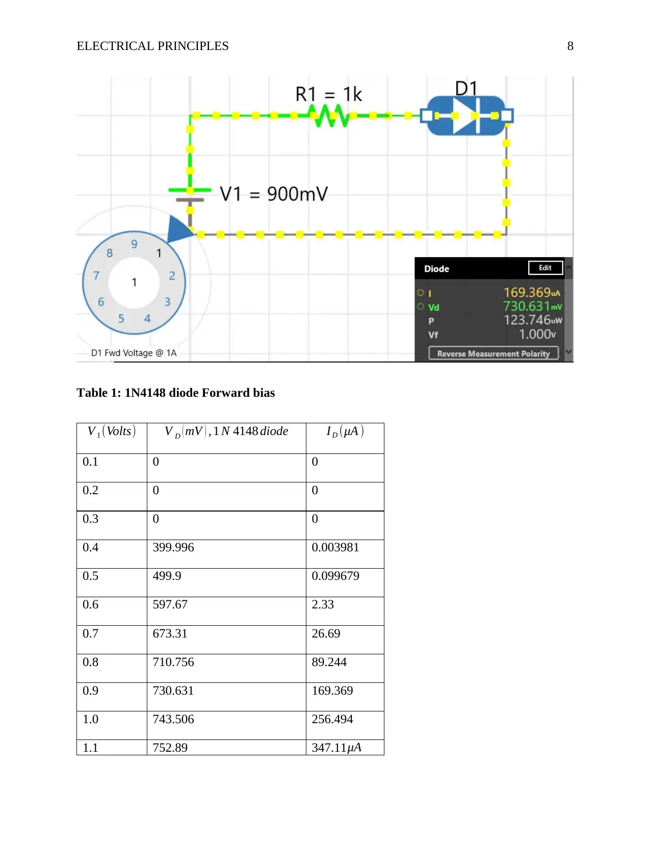
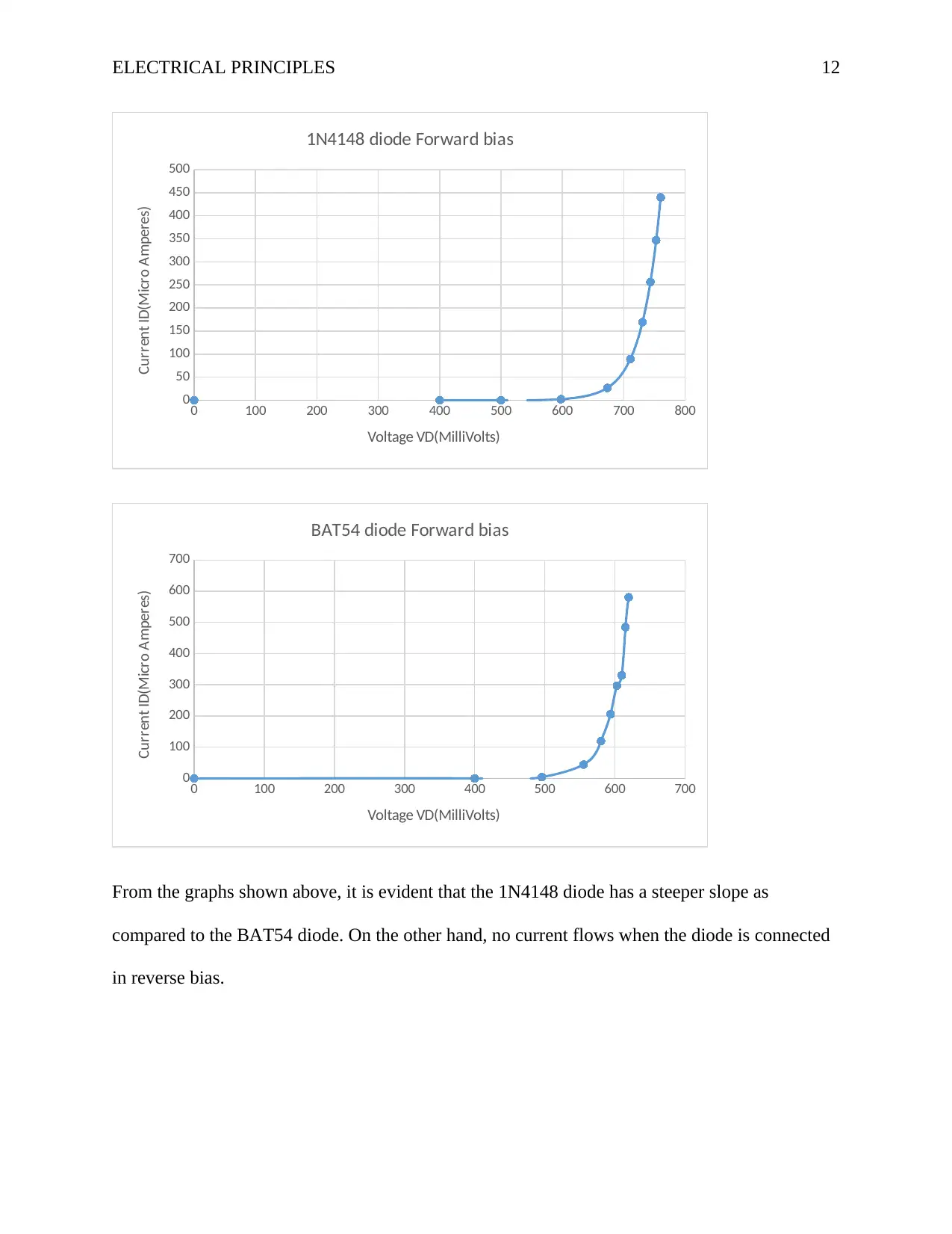
This document presents a comprehensive solution to an Electrical and Electronic Principles assignment, focusing on DC networks. The assignment covers various aspects of DC circuit theory, including calculating current, voltage, and resistance within DC networks. It demonstrates the application of Kirchhoff's laws to determine currents in a network with four nodes and the power dissipated in a load resistor containing two voltage sources. The solution also includes practical circuit measurements using a multimeter. Furthermore, the assignment analyzes and compares the forward and reverse characteristics of two different types of semiconductor diodes, specifically the 1N4148 and BAT54 diodes, through tabular data and graphical analysis. The document provides detailed calculations, circuit diagrams, and comparative analyses to provide a complete understanding of the concepts.
Document Page
Running head: ELECTRICAL PRINCIPLES 1
Electrical and Electronic Principles
Name
Institution
tabler-icon-diamond-filled.svg

Paraphrase This Document

Need a fresh take? Get an instant paraphrase of this document with our AI Paraphraser
Document Page
ELECTRICAL PRINCIPLES 2
Electrical and Electronic Principles
Task 1 Circuit A
Part (i)
R1=R2=100 Ω , R3 =550 Ω , R4=330 Ω , R5=200 Ω , supply voltage=12V
Total Resistance , R=R1|R2+R3+R4|R5
¿ R1 R2
R1+ R2
+ R3 + R4 R5
R4 + R5
R1 R2
R1+ R2
= 100 ×100
100+100 =50 Ω
R4 R5
R4 + R5
= 330 ×200
330+200 =120 Ω
Total Resistance , R=50+550+120=720 Ω
Part (ii)
Current drawn ¿ supply , I= Supply Voltage
Total Resistance
¿ 12
720 A= 1
60 A=0.016667 A=16.667 mA
Part (iii)
Voltage across V 1=I R1 R2
R1+ R2
=0.016667 A ×50 Ω=0.8333 V
Voltage across V 2 =I R3=0.016667 A ×550 Ω=9.1667 V
Document Page
ELECTRICAL PRINCIPLES 3
Voltage across V 3 =I R4 R5
R4 + R5
=0.016667 A ×120 Ω=2V
Part (iv)
Current through R4=I R5
R4 + R5
=0.016667 A × 200 Ω
(330+200)Ω
¿ 0.016667 A × 200
550 =0.00606 A=6.06 mA
Task 1 Circuit B
Part (i)
R1=20 Ω, R2=60 Ω, R3=10 Ω, R4 =60 Ω , R5=600 Ω , R6=2000 Ω supply voltage=3V
Total Resistance , R=R1¿ R2¿ R3+R4¿ R5+ R6
¿ R1 R2
R1+ R2
¿ R3+ R4 R5
R4+ R5
+ R6
R1 R2
R1+ R2
= 20 ×60
20+60 =15 Ω
R1 R2
R1+ R2
¿ R3= 15× 10
15+10 =6 Ω
R4 R5
R4 + R5
= 60 ×600
60+ 600 = 600
11 Ω
Total Resistance , R=6+ 600
11 +2000= 22 66 6
11 Ω=20 60.545 5 Ω
Part (ii)
Document Page
ELECTRICAL PRINCIPLES 4
Current drawn ¿ supply , I= Supply Voltage
Total Resistance
¿ 3V
2060.5455 Ω=1.4 55925× 103 A=1.455925 mA
Part (iii)
Voltage across V 1=I R1 R2
R1+ R2
¿ R3 =1.455925× 103 A × 6 Ω=0.008736 V
Voltage across V 2 =I R4 R5
R4 + R5
=1.455925 ×103 A × 600
11 Ω=0.0 79414 2V
Voltage across V 3 =I R6=1.455925 ×103 A × 2000 Ω=2.9 118503V
Part (iv)
Current through R5=I R4
R4 + R5
=1.455925 ×103 A × 60 Ω
(60+600) Ω
¿ 1.491456 ×103 A × 60
660 =0.00013 2356 A
Task 2
tabler-icon-diamond-filled.svg

Paraphrase This Document

Need a fresh take? Get an instant paraphrase of this document with our AI Paraphraser
Document Page
ELECTRICAL PRINCIPLES 5
Applying Kirchhoff’s Current Law at junction C we get:
I 1+I2=I3 Equation 1
Then, we apply Kirchhoff’s Voltage Law to loop 1 to get the equation:
V 1R1 I1 R2 I3=0
Substituting the values of voltage and resistance and simplifying yields:
62 I 14 I3=0
2 I1 +4 I3 =6
I 1+2 I3=3 Equation2
Then, we apply Kirchhoff’s Voltage Law to loop 2 to get the equation:
V 2R3 I2R2 I 3=0 Equation 3
Substituting the values of voltage and resistance and simplifying yields:
Document Page
ELECTRICAL PRINCIPLES 6
122 I 24 I3=0
2 I2 +4 I3 =12
I 2+ 2 I3=6 Equation3
Substituting the value of I 3 in equation 1 into equation 2 we get:
I 1+2 (I1 + I2)=3
I 1+2 I 1+2 I2=3
3 I1 +2 I 2=3 equation 4
Substituting the value of I 3 in equation 1 into equation 3 we get:
I 2+ 2(I1 + I2)=6
I 2+2 I 1+2 I2=6
2 I1 +3 I 2=6 equation 5
Then solve the simultaneous equations 4 and 5 as follows:
Multiply equation 4 with 2 and equation 5 with 3 to get:
2 ( 3 I1 +2 I2=3 ) equation 4 6 I1 +4 I 2=6
( 2 I1 +3 I2=6 ) 3 equation 5 6 I1 +9 I2=18
Then subtract the resulting equations from each other to get:
( 6 I1+ 9 I2 ) ( 6 I1 + 4 I 2 ) =186
5 I2 =12
Document Page
ELECTRICAL PRINCIPLES 7
I 2=12
5 =2.4 A
Substituting I2 =2.4 A into equation 4 yields
3 I1 +2 ( 2.4 )=3 equation 4
3 I1 =34.8=1.8
I 1=1.8
3 =0.6 A
Then from equation 1,
I 3=I 1+I2=0.6 +2.4=1.8 A
Therefore , I1=0.6 A , I 2=2.4 A ,I3=1.8 A
The power dissipated by R2=I 3
2 R2=1.82 ×4=12.96 W
Task 3 Circuit A: 1N4148 diode
tabler-icon-diamond-filled.svg

Paraphrase This Document

Need a fresh take? Get an instant paraphrase of this document with our AI Paraphraser
Document Page
ELECTRICAL PRINCIPLES 8
Table 1: 1N4148 diode Forward bias
V 1 (Volts) V D ( mV ) , 1 N 4148 diode I D (μA )
0.1 0 0
0.2 0 0
0.3 0 0
0.4 399.996 0.003981
0.5 499.9 0.099679
0.6 597.67 2.33
0.7 673.31 26.69
0.8 710.756 89.244
0.9 730.631 169.369
1.0 743.506 256.494
1.1 752.89 347.11 μA
Document Page
ELECTRICAL PRINCIPLES 9
1.2 760.23 439.77μA
Table 2: 1N4148 diode Reverse bias
V 1 (Volts) V D ( Volts ) ,1 N 4148 diode I D (mA )
2 0 0
4 0 0
6 0 0
8 0 0
10 0 0
12 0 0
Task 3 Circuit B (BAT54 diode)
Document Page
ELECTRICAL PRINCIPLES 10
Table 3: BAT54 diode Forward bias
V 1 (Volts) V D ( mV ) , BAT 54 diode I D (μA )
0.1 0 0
0.2 0 0
0.3 0 0
0.4 399.911 0.088547
0.5 495.885 4.115
0.6 555.439 44.561
0.7 580.169 119.831
0.8 593.745 206.255
0.9 602.871 297.129
1.0 609.691 330.309
tabler-icon-diamond-filled.svg

Paraphrase This Document

Need a fresh take? Get an instant paraphrase of this document with our AI Paraphraser
Document Page
ELECTRICAL PRINCIPLES 11
1.1 615.115 484.885
1.2 619.61 580.39
Table 4: BAT54 diode Reverse bias
Task 4
V 1 (Volts) V D ( Volts ) , BAT 54 diode I D (mA )
2 0 0
4 0 0
6 0 0
8 0 0
10 0 0
12 0 0
Document Page
ELECTRICAL PRINCIPLES 12
0 100 200 300 400 500 600 700 800
0
50
100
150
200
250
300
350
400
450
500
1N4148 diode Forward bias
Voltage VD(MilliVolts)
Current ID(Micro Amperes)
0 100 200 300 400 500 600 700
0
100
200
300
400
500
600
700
BAT54 diode Forward bias
Voltage VD(MilliVolts)
Current ID(Micro Amperes)
From the graphs shown above, it is evident that the 1N4148 diode has a steeper slope as
compared to the BAT54 diode. On the other hand, no current flows when the diode is connected
in reverse bias.
chevron_up_icon
1 out of 12
circle_padding
hide_on_mobile
zoom_out_icon
[object Object]