Electrical Engineering Assignment: Power Systems and Renewable Energy
VerifiedAdded on 2023/01/18
|25
|6586
|34
Homework Assignment
AI Summary
This electrical engineering assignment solution addresses three key problems in power systems and renewable energy. The first question examines the merits and demerits of intentional islanding in a microgrid, followed by calculations related to a wind farm connected to a large grid, including equivalent impedance, power output, and voltage iterations. The second question delves into a solar power system, calculating daily water discharge, battery capacity, and the number of PV modules required, considering efficiency and derating. The final question analyzes two wind farms connected to a utility grid, calculating full-load voltage at a bus and the actual power reaching the grid, incorporating transformer and line parameters.

Student
Instructor
Analogue and digital electronics
Date
Instructor
Analogue and digital electronics
Date
Paraphrase This Document
Need a fresh take? Get an instant paraphrase of this document with our AI Paraphraser
QUESTION 1
a) Describing merits and demerits of intentional islanding of a micro grid
Islanding is management procedure that entails configuring and implementation of the power system
at the distribution level to protect sensible and vulnerable loads from power outages. It guarantees
continuous supply of electric power even when the main utility collapses [1].
Disadvantage.
Islanding becomes dangerous when power utility company is not in charge on the control system.
This could cause high probably of equipment failure thereby compromising o the safety of the
personnel [2].
Islanding, whose source of interest is on renewable energy is not possible to satisfactory stand on its
own since renewable energy is always intermittent and the storage for enough supply compared to the
traditional method is not economically viable.
Advantages of islanding
Islanding technique truly increases reliability of power supply especially when the system is
configured with enough storage bank. Regardless of the behavior of the main utility supply,
customers’ equipment are not subjected to power outage [3].
b)
Data for part b)
From fig showing the schematic diagram of wind farm that connects a large 50 Hz grid via a
10MVA, 690/1100V transformer. The windfarm has 50Hz, 690V, twelve identical wind turbines
(induction) generators and each generator is rated at 747kVA. The table on the question paper
gave the parameters of the wind turbine generator referred to the stator side in Ω/phase. The
transformer has a leakage reactance of 0.061 pu. The real power loss of the transformer is
negligible. The slip of the induction generator is -0.01847.
i) Calculating full load power
V ¿=690 V ,V ∅ =398.4 V , Srated=747 kVA
Finding the equivalent impedance of a single generator.
R1=0.0048Ω , X1 = j 0.0680Ω , R2=0.0127Ω, X2 = j 0.0897 Ω , X m= j 2.8100 Ω
Slip , S=−0.01847
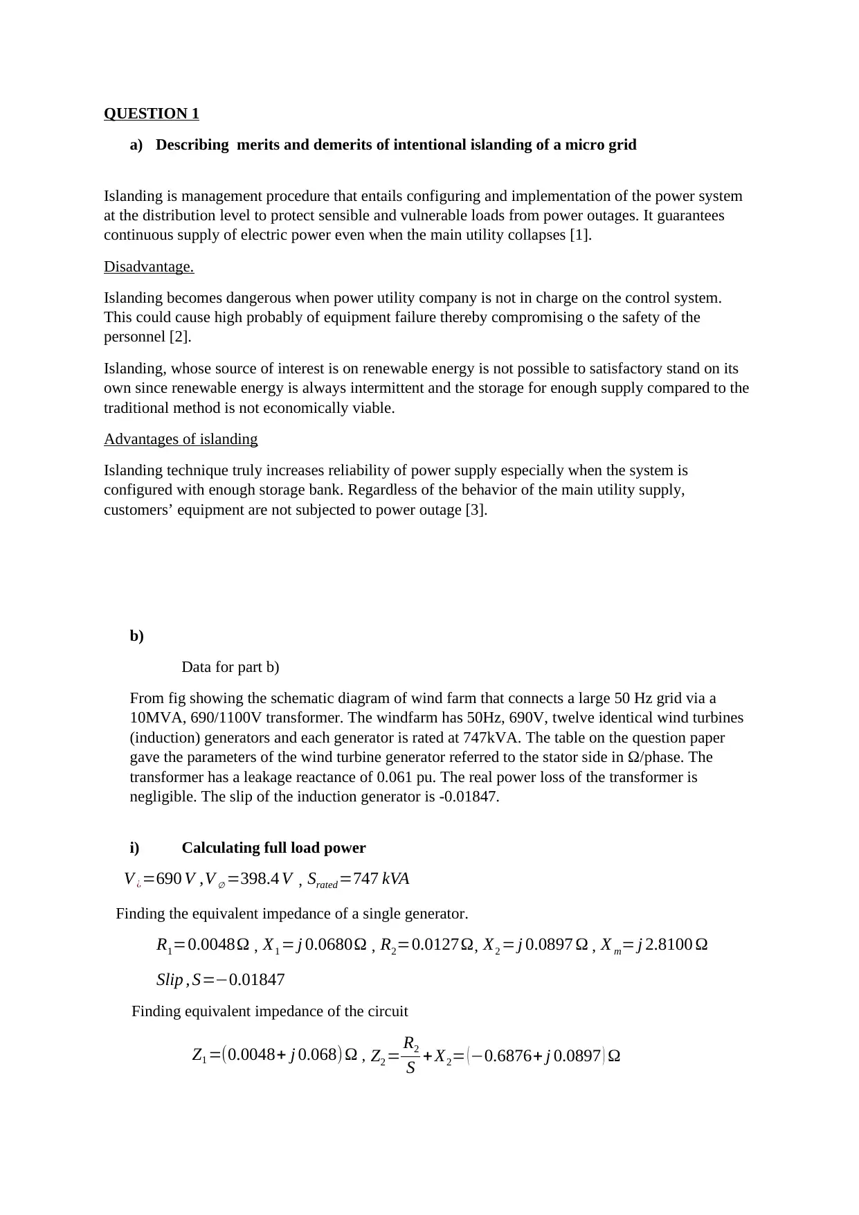
Finding equivalent impedance of the circuit
Z1 =(0.0048+ j 0.068) Ω , Z2 = R2
S + X2= ( −0.6876+ j 0.0897 ) Ω
a) Describing merits and demerits of intentional islanding of a micro grid
Islanding is management procedure that entails configuring and implementation of the power system
at the distribution level to protect sensible and vulnerable loads from power outages. It guarantees
continuous supply of electric power even when the main utility collapses [1].
Disadvantage.
Islanding becomes dangerous when power utility company is not in charge on the control system.
This could cause high probably of equipment failure thereby compromising o the safety of the
personnel [2].
Islanding, whose source of interest is on renewable energy is not possible to satisfactory stand on its
own since renewable energy is always intermittent and the storage for enough supply compared to the
traditional method is not economically viable.
Advantages of islanding
Islanding technique truly increases reliability of power supply especially when the system is
configured with enough storage bank. Regardless of the behavior of the main utility supply,
customers’ equipment are not subjected to power outage [3].
b)
Data for part b)
From fig showing the schematic diagram of wind farm that connects a large 50 Hz grid via a
10MVA, 690/1100V transformer. The windfarm has 50Hz, 690V, twelve identical wind turbines
(induction) generators and each generator is rated at 747kVA. The table on the question paper
gave the parameters of the wind turbine generator referred to the stator side in Ω/phase. The
transformer has a leakage reactance of 0.061 pu. The real power loss of the transformer is
negligible. The slip of the induction generator is -0.01847.
i) Calculating full load power
V ¿=690 V ,V ∅ =398.4 V , Srated=747 kVA
Finding the equivalent impedance of a single generator.
R1=0.0048Ω , X1 = j 0.0680Ω , R2=0.0127Ω, X2 = j 0.0897 Ω , X m= j 2.8100 Ω
Slip , S=−0.01847
Finding equivalent impedance of the circuit
Z1 =(0.0048+ j 0.068) Ω , Z2 = R2
S + X2= ( −0.6876+ j 0.0897 ) Ω
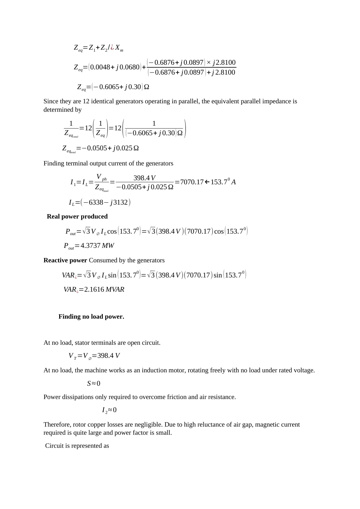
Zeq=Z1+ Z2 /¿ Xm
Zeq= ( 0.0048+ j 0.0680 ) + ( −0.6876+ j 0.0897 ) × j2.8100
( −0.6876+ j0.0897 ) + j 2.8100
Zeq= ( −0.6065+ j 0.30 ) Ω
Since they are 12 identical generators operating in parallel, the equivalent parallel impedance is
determined by
1
Zeqtotal
=12 ( 1
Zeq )=12 ( 1
(−0.6065+ j 0.30 ) Ω )
Zeqtotal
=−0.0505+ j0.025 Ω
Finding terminal output current of the generators
I 1=I L= V ph
Zeqtotal
= 398.4 V
−0.0505+ j 0.025 Ω =7070.17←153.70 A
I L=(−6338− j3132)
Real power produced
Pout= √ 3 V ∅ I L cos ( 153. 70 ) = √ 3(398.4 V )(7070.17) cos ( 153.70 )
Pout=4.3737 MW
Reactive power Consumed by the generators
VAR¿= √ 3 V ∅ I L sin ( 153. 70 ) = √ 3 (398.4 V )(7070.17) sin ( 153.70 )
VAR¿=2.1616 MVAR
Finding no load power.
At no load, stator terminals are open circuit.
V T =V ∅=398.4 V
At no load, the machine works as an induction motor, rotating freely with no load under rated voltage.
S ≈ 0
Power dissipations only required to overcome friction and air resistance.
I 2 ≈ 0
Therefore, rotor copper losses are negligible. Due to high reluctance of air gap, magnetic current
required is quite large and power factor is small.
Circuit is represented as
⊘ This is a preview!⊘
Do you want full access?
Subscribe today to unlock all pages.
Trusted by 1+ million students worldwide
V ph
I 10
≈(X1 + Xm)
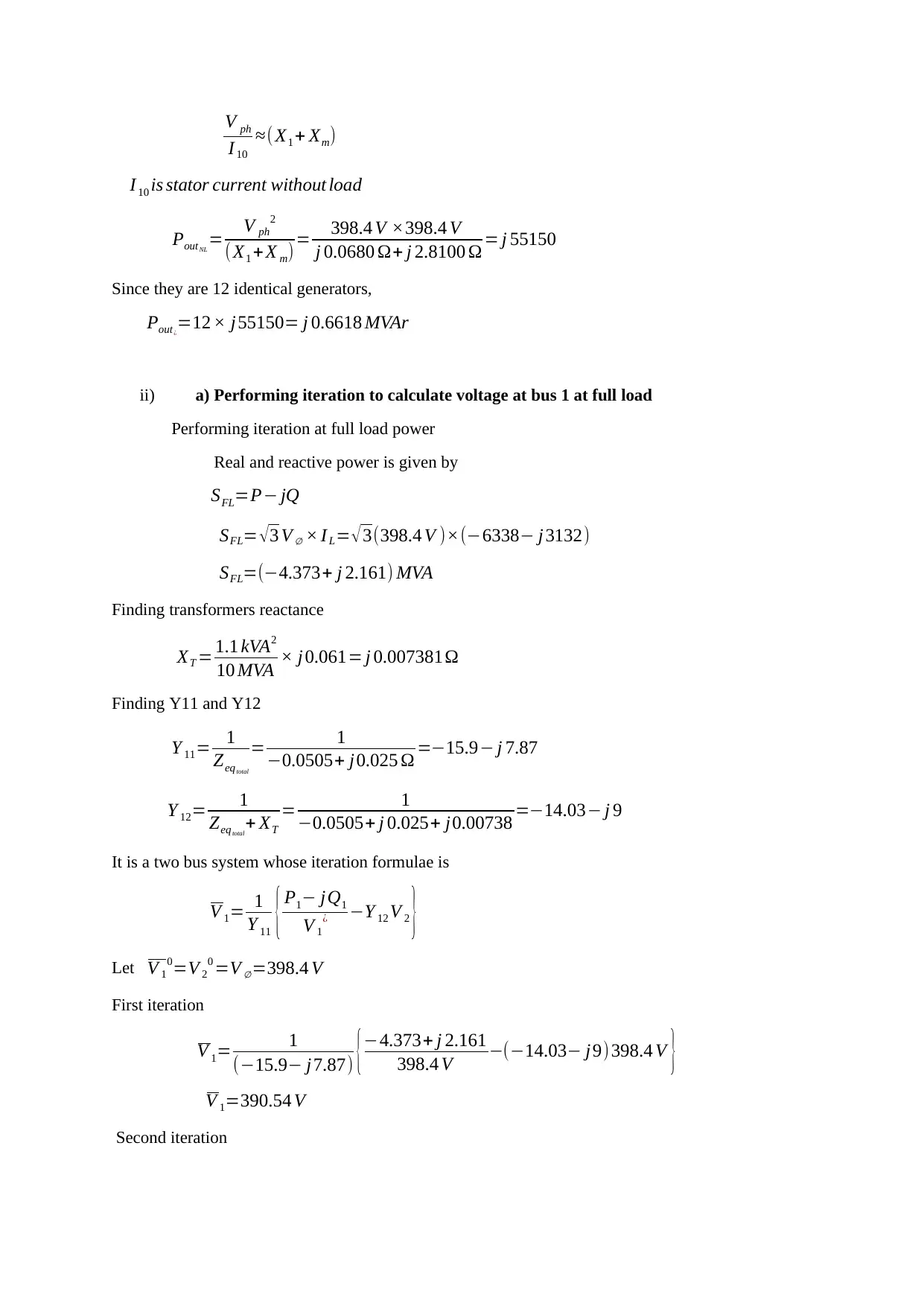
I 10 is stator current without load
PoutNL
= V ph
2
(X1 + X m)= 398.4 V ×398.4 V
j 0.0680 Ω+ j 2.8100 Ω = j 55150
Since they are 12 identical generators,
Pout¿
=12 × j55150= j 0.6618 MVAr
ii) a) Performing iteration to calculate voltage at bus 1 at full load
Performing iteration at full load power
Real and reactive power is given by
SFL=P− jQ
SFL= √ 3 V ∅ × I L= √ 3(398.4 V )×(−6338− j 3132)
SFL=(−4.373+ j 2.161) MVA
Finding transformers reactance
XT = 1.1 kVA2
10 MVA × j 0.061= j 0.007381Ω
Finding Y11 and Y12
Y 11= 1
Zeqtotal
= 1
−0.0505+ j0.025 Ω =−15.9− j 7.87
Y 12= 1
Zeqtotal
+ XT
= 1
−0.0505+ j 0.025+ j0.00738 =−14.03− j 9
It is a two bus system whose iteration formulae is
V 1= 1
Y 11 { P1− jQ1
V 1
¿ −Y 12 V 2 }
Let V 1
0=V 2
0 =V ∅=398.4 V
First iteration
V 1= 1
(−15.9− j7.87) {−4.373+ j 2.161
398.4 V −(−14.03− j9) 398.4 V }
V 1=390.54 V
Second iteration
I 10
≈(X1 + Xm)
I 10 is stator current without load
PoutNL
= V ph
2
(X1 + X m)= 398.4 V ×398.4 V
j 0.0680 Ω+ j 2.8100 Ω = j 55150
Since they are 12 identical generators,
Pout¿
=12 × j55150= j 0.6618 MVAr
ii) a) Performing iteration to calculate voltage at bus 1 at full load
Performing iteration at full load power
Real and reactive power is given by
SFL=P− jQ
SFL= √ 3 V ∅ × I L= √ 3(398.4 V )×(−6338− j 3132)
SFL=(−4.373+ j 2.161) MVA
Finding transformers reactance
XT = 1.1 kVA2
10 MVA × j 0.061= j 0.007381Ω
Finding Y11 and Y12
Y 11= 1
Zeqtotal
= 1
−0.0505+ j0.025 Ω =−15.9− j 7.87
Y 12= 1
Zeqtotal
+ XT
= 1
−0.0505+ j 0.025+ j0.00738 =−14.03− j 9
It is a two bus system whose iteration formulae is
V 1= 1
Y 11 { P1− jQ1
V 1
¿ −Y 12 V 2 }
Let V 1
0=V 2
0 =V ∅=398.4 V
First iteration
V 1= 1
(−15.9− j7.87) {−4.373+ j 2.161
398.4 V −(−14.03− j9) 398.4 V }
V 1=390.54 V
Second iteration
Paraphrase This Document
Need a fresh take? Get an instant paraphrase of this document with our AI Paraphraser
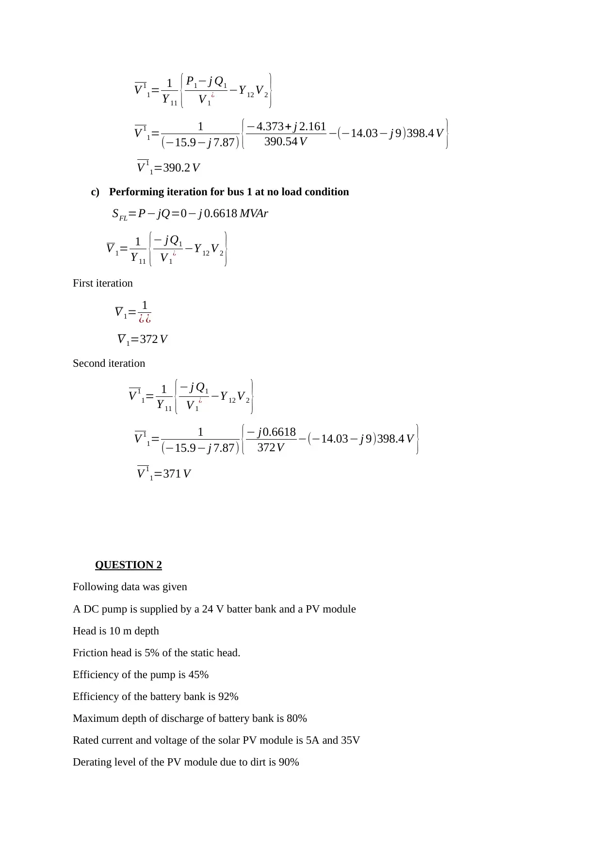
V 1
1= 1
Y 11 { P1− j Q1
V 1
¿ −Y 12 V 2 }
V 1
1= 1
(−15.9− j 7.87) {−4.373+ j 2.161
390.54 V −(−14.03− j 9)398.4 V }
V 1
1=390.2 V
c) Performing iteration for bus 1 at no load condition
SFL=P− jQ=0− j 0.6618 MVAr
V 1= 1
Y 11 {− jQ1
V 1
¿ −Y 12 V 2 }
First iteration
V 1= 1
¿ ¿
V 1=372 V
Second iteration
V 1
1= 1
Y 11 {− j Q1
V 1
¿ −Y 12 V 2 }
V 1
1= 1
(−15.9− j 7.87) {− j0.6618
372V −(−14.03− j 9)398.4 V }
V 1
1=371 V
QUESTION 2
Following data was given
A DC pump is supplied by a 24 V batter bank and a PV module
Head is 10 m depth
Friction head is 5% of the static head.
Efficiency of the pump is 45%
Efficiency of the battery bank is 92%
Maximum depth of discharge of battery bank is 80%
Rated current and voltage of the solar PV module is 5A and 35V
Derating level of the PV module due to dirt is 90%
1= 1
Y 11 { P1− j Q1
V 1
¿ −Y 12 V 2 }
V 1
1= 1
(−15.9− j 7.87) {−4.373+ j 2.161
390.54 V −(−14.03− j 9)398.4 V }
V 1
1=390.2 V
c) Performing iteration for bus 1 at no load condition
SFL=P− jQ=0− j 0.6618 MVAr
V 1= 1
Y 11 {− jQ1
V 1
¿ −Y 12 V 2 }
First iteration
V 1= 1
¿ ¿
V 1=372 V
Second iteration
V 1
1= 1
Y 11 {− j Q1
V 1
¿ −Y 12 V 2 }
V 1
1= 1
(−15.9− j 7.87) {− j0.6618
372V −(−14.03− j 9)398.4 V }
V 1
1=371 V
QUESTION 2
Following data was given
A DC pump is supplied by a 24 V batter bank and a PV module
Head is 10 m depth
Friction head is 5% of the static head.
Efficiency of the pump is 45%
Efficiency of the battery bank is 92%
Maximum depth of discharge of battery bank is 80%
Rated current and voltage of the solar PV module is 5A and 35V
Derating level of the PV module due to dirt is 90%
Average solar insolation of the site is 5.5kWh/m2/day.
The daily energy yield is fully utilized during the same day.
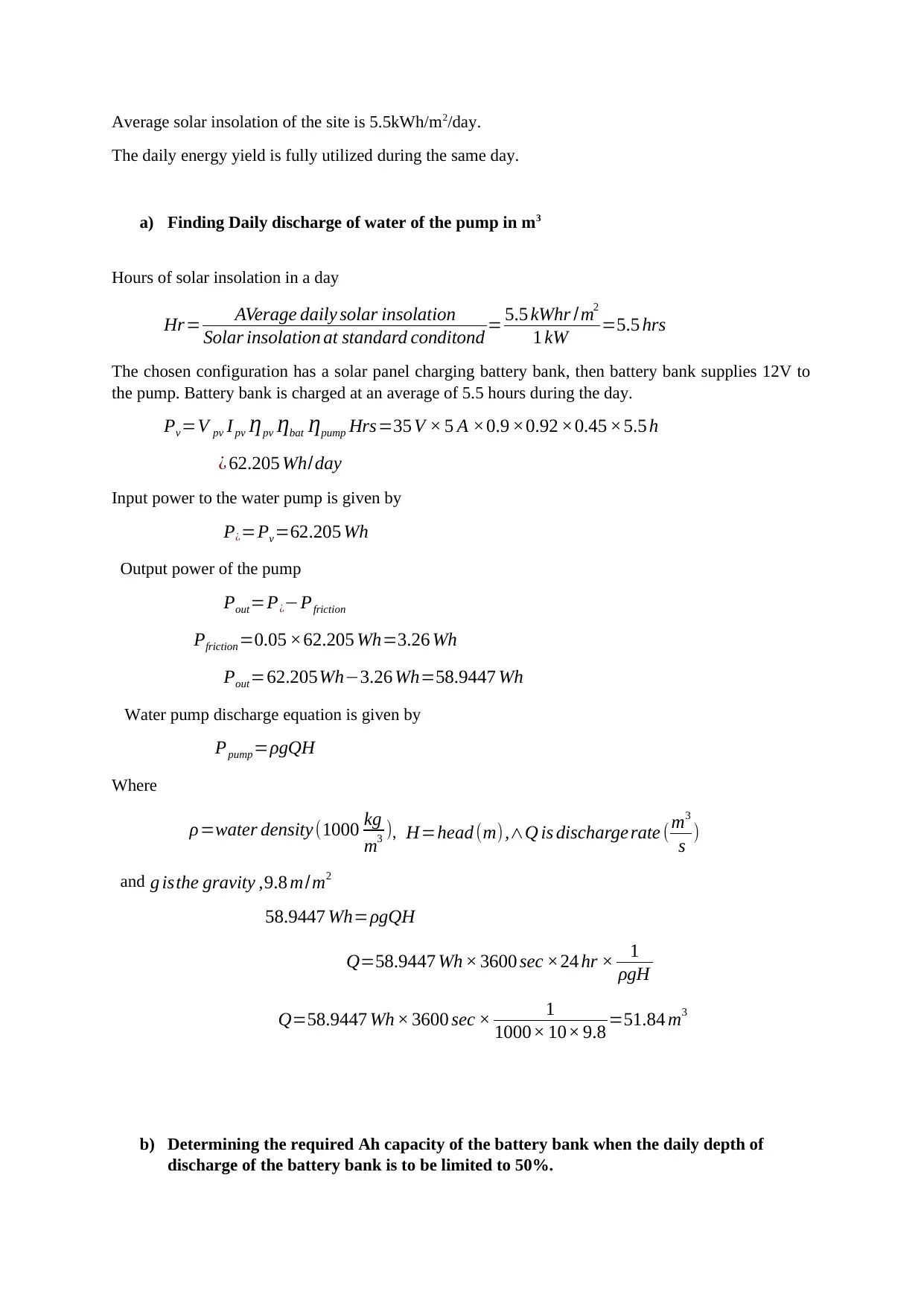
a) Finding Daily discharge of water of the pump in m3
Hours of solar insolation in a day
Hr= AVerage daily solar insolation
Solar insolation at standard conditond = 5.5 kWhr /m2
1 kW =5.5 hrs
The chosen configuration has a solar panel charging battery bank, then battery bank supplies 12V to
the pump. Battery bank is charged at an average of 5.5 hours during the day.
Pv=V pv I pv Ƞpv Ƞbat Ƞpump Hrs=35 V × 5 A ×0.9 ×0.92 ×0.45 ×5.5 h
¿ 62.205 Wh/day
Input power to the water pump is given by
P¿=Pv=62.205 Wh
Output power of the pump
Pout=P¿−Pfriction
Pfriction=0.05 ×62.205 Wh=3.26 Wh
Pout=62.205Wh−3.26 Wh=58.9447 Wh
Water pump discharge equation is given by
Ppump=ρgQH
Where
ρ=water density (1000 kg
m3 ), H=head (m),∧Q is discharge rate ( m3
s )
and g isthe gravity ,9.8 m/m2
58.9447 Wh=ρgQH
Q=58.9447 Wh × 3600 sec ×24 hr × 1
ρgH
Q=58.9447 Wh × 3600 sec × 1
1000× 10× 9.8 =51.84 m3
b) Determining the required Ah capacity of the battery bank when the daily depth of
discharge of the battery bank is to be limited to 50%.
The daily energy yield is fully utilized during the same day.
a) Finding Daily discharge of water of the pump in m3
Hours of solar insolation in a day
Hr= AVerage daily solar insolation
Solar insolation at standard conditond = 5.5 kWhr /m2
1 kW =5.5 hrs
The chosen configuration has a solar panel charging battery bank, then battery bank supplies 12V to
the pump. Battery bank is charged at an average of 5.5 hours during the day.
Pv=V pv I pv Ƞpv Ƞbat Ƞpump Hrs=35 V × 5 A ×0.9 ×0.92 ×0.45 ×5.5 h
¿ 62.205 Wh/day
Input power to the water pump is given by
P¿=Pv=62.205 Wh
Output power of the pump
Pout=P¿−Pfriction
Pfriction=0.05 ×62.205 Wh=3.26 Wh
Pout=62.205Wh−3.26 Wh=58.9447 Wh
Water pump discharge equation is given by
Ppump=ρgQH
Where
ρ=water density (1000 kg
m3 ), H=head (m),∧Q is discharge rate ( m3
s )
and g isthe gravity ,9.8 m/m2
58.9447 Wh=ρgQH
Q=58.9447 Wh × 3600 sec ×24 hr × 1
ρgH
Q=58.9447 Wh × 3600 sec × 1
1000× 10× 9.8 =51.84 m3
b) Determining the required Ah capacity of the battery bank when the daily depth of
discharge of the battery bank is to be limited to 50%.
⊘ This is a preview!⊘
Do you want full access?
Subscribe today to unlock all pages.
Trusted by 1+ million students worldwide

Wh capacity of the battery bank
Whbat= Ppv 0
DoD × Ƞbat
Where Ppv 0=V pv I pv=35 V × 5 A
Whbat=35 V ×5 A
0.5 × 0.92 =380.43 Wh
Making autonomous days as 5 days
Converting Wh to Ah
Ah= Whbat
V bat
× 5 days=380.43 Wh ×5 days
24 =80 Ah
c) Determining the number of batteries required and sketch how they are connected in the
battery bank when an individual batter in part b) is rated at 6V, 16Ah,.
Storage of battery capacity
Ah=80 Ah
Battery is storage is affected by DoD (Depth of Discharge permitted) and the efficiency of the
inverter.
Terminal voltage of the motor pump
V T =12V
Therefore, batteries in series are 2.
6 V +6 V =12V
Total batteries
BT = 80 Ah
16 AH =5
To balance batteries in series and parallel, let number of batteries be 6
Batteries in parallel
B¿=6
2 =3 batteries
Paraphrase This Document
Need a fresh take? Get an instant paraphrase of this document with our AI Paraphraser

Fig 1: Battery bank connection
d) If the required daily discharge of water is 30m3/day, determine how many PV modules
are needed and sketch how they are connected.
ρ=water density (1000 kg
m3 ), H=head (m) ,∧Q is discharge rate (m3
s )
and g isthe gravity ,9.8 m/m2
Total power output
Ppump=ρgQH
Ppump=(1000 kg
m3 )(9.8 m/m2) 30 m3 ×10
Ppump=2940 kWh
Finding PV modules required
Pv=k V pv I pv Ƞpv=Ppump
k = Ppump
Pv
= 2940 kWh
35× 5× 0.9 ×5.5 hr =3394 panels
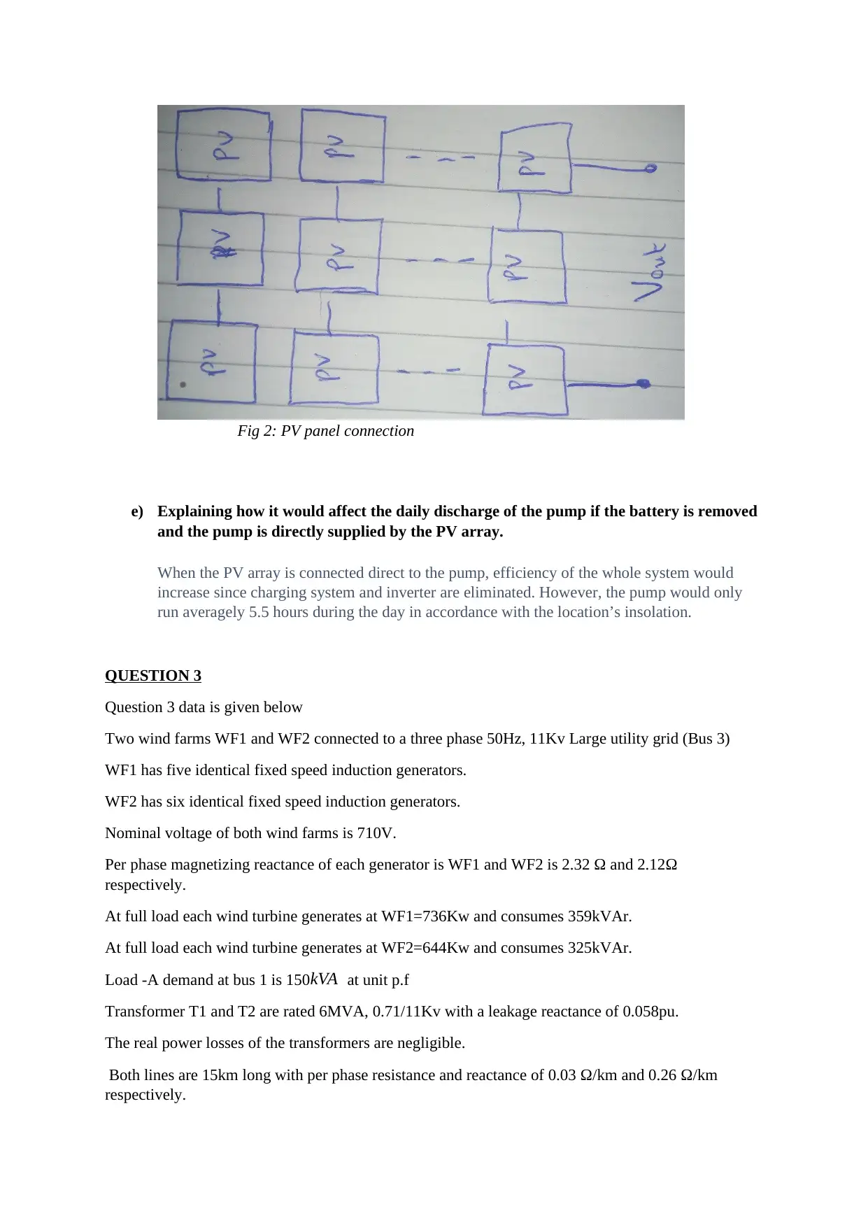
Fig 2: PV panel connection
e) Explaining how it would affect the daily discharge of the pump if the battery is removed
and the pump is directly supplied by the PV array.
When the PV array is connected direct to the pump, efficiency of the whole system would
increase since charging system and inverter are eliminated. However, the pump would only
run averagely 5.5 hours during the day in accordance with the location’s insolation.
QUESTION 3
Question 3 data is given below
Two wind farms WF1 and WF2 connected to a three phase 50Hz, 11Kv Large utility grid (Bus 3)
WF1 has five identical fixed speed induction generators.
WF2 has six identical fixed speed induction generators.
Nominal voltage of both wind farms is 710V.
Per phase magnetizing reactance of each generator is WF1 and WF2 is 2.32 Ω and 2.12Ω
respectively.
At full load each wind turbine generates at WF1=736Kw and consumes 359kVAr.
At full load each wind turbine generates at WF2=644Kw and consumes 325kVAr.
Load -A demand at bus 1 is 150 kVA at unit p.f
Transformer T1 and T2 are rated 6MVA, 0.71/11Kv with a leakage reactance of 0.058pu.
The real power losses of the transformers are negligible.
Both lines are 15km long with per phase resistance and reactance of 0.03 Ω/km and 0.26 Ω/km
respectively.
⊘ This is a preview!⊘
Do you want full access?
Subscribe today to unlock all pages.
Trusted by 1+ million students worldwide
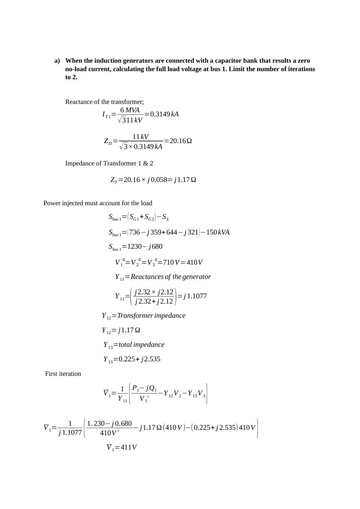
a) When the induction generators are connected with a capacitor bank that results a zero
no-load current, calculating the full load voltage at bus 1. Limit the number of iterations
to 2.
Reactance of the transformer;
I T 1= 6 MVA
√ 311 kV =0.3149 kA
ZTI = 11 kV
√ 3× 0.3149 kA =20.16Ω
Impedance of Transformer 1 & 2
ZT =20.16 × j 0.058= j1.17 Ω
Power injected must account for the load
Sbus 1= ( SG 1 +SG 2 ) −S L
Sbus 1= ( 736− j 359+644− j 321 )−150 kVA
Sbus 1=1230− j680
V 1
0=V 2
0 =V 3
0=710 V =410V
Y 11=Reactances of the generator
Y 11=( j2.32 × j2.12
j 2.32+ j 2.12 )= j 1.1077
Y 12=Transformer impedance
Y 12= j1.17 Ω
Y 13=total impedance
Y 13=0.225+ j2.535
First iteration
V 1= 1
Y 11 { P1− jQ1
V 1
¿ −Y 12 V 2 −Y 13 V 3 }
V 1= 1
j 1.1077 { 1. 230− j 0.680
410V ¿ − j1.17 Ω (410 V )−(0.225+ j 2.535) 410 V }
V 1=411V
Paraphrase This Document
Need a fresh take? Get an instant paraphrase of this document with our AI Paraphraser
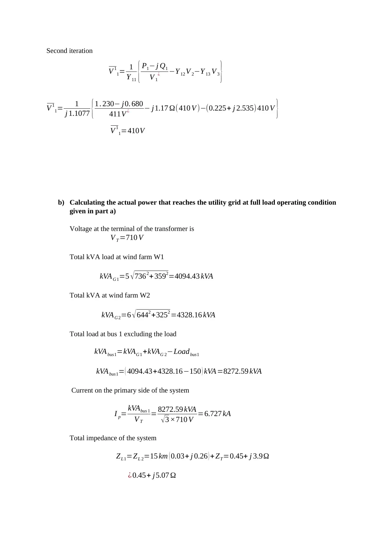
Second iteration
V 1
1= 1
Y 11 { P1− j Q1
V 1
¿ −Y 12 V 2−Y 13 V 3 }
V 1
1= 1
j 1.1077 {1 . 230− j0. 680
411V ¿ − j1.17 Ω( 410 V )−(0.225+ j 2.535)410 V }
V 1
1=410V
b) Calculating the actual power that reaches the utility grid at full load operating condition
given in part a)
Voltage at the terminal of the transformer is
V T =710 V
Total kVA load at wind farm W1
kVAG 1=5 √ 7362+ 3592=4094.43 kVA
Total kVA at wind farm W2
kVAG 2=6 √ 6442 +3252 =4328.16 kVA
Total load at bus 1 excluding the load
kVAbus1=kVAG 1 +kVAG 2−Loadbus1
kVAbus1= ( 4094.43+4328.16−150 ) kVA =8272.59 kVA
Current on the primary side of the system
I p= kVAbus 1
V T
= 8272.59 kVA
√3 ×710 V =6.727 kA
Total impedance of the system
ZL1=ZL 2=15 km ( 0.03+ j 0.26 ) + ZT=0.45+ j 3.9Ω
¿ 0.45+ j5.07 Ω
V 1
1= 1
Y 11 { P1− j Q1
V 1
¿ −Y 12 V 2−Y 13 V 3 }
V 1
1= 1
j 1.1077 {1 . 230− j0. 680
411V ¿ − j1.17 Ω( 410 V )−(0.225+ j 2.535)410 V }
V 1
1=410V
b) Calculating the actual power that reaches the utility grid at full load operating condition
given in part a)
Voltage at the terminal of the transformer is
V T =710 V
Total kVA load at wind farm W1
kVAG 1=5 √ 7362+ 3592=4094.43 kVA
Total kVA at wind farm W2
kVAG 2=6 √ 6442 +3252 =4328.16 kVA
Total load at bus 1 excluding the load
kVAbus1=kVAG 1 +kVAG 2−Loadbus1
kVAbus1= ( 4094.43+4328.16−150 ) kVA =8272.59 kVA
Current on the primary side of the system
I p= kVAbus 1
V T
= 8272.59 kVA
√3 ×710 V =6.727 kA
Total impedance of the system
ZL1=ZL 2=15 km ( 0.03+ j 0.26 ) + ZT=0.45+ j 3.9Ω
¿ 0.45+ j5.07 Ω
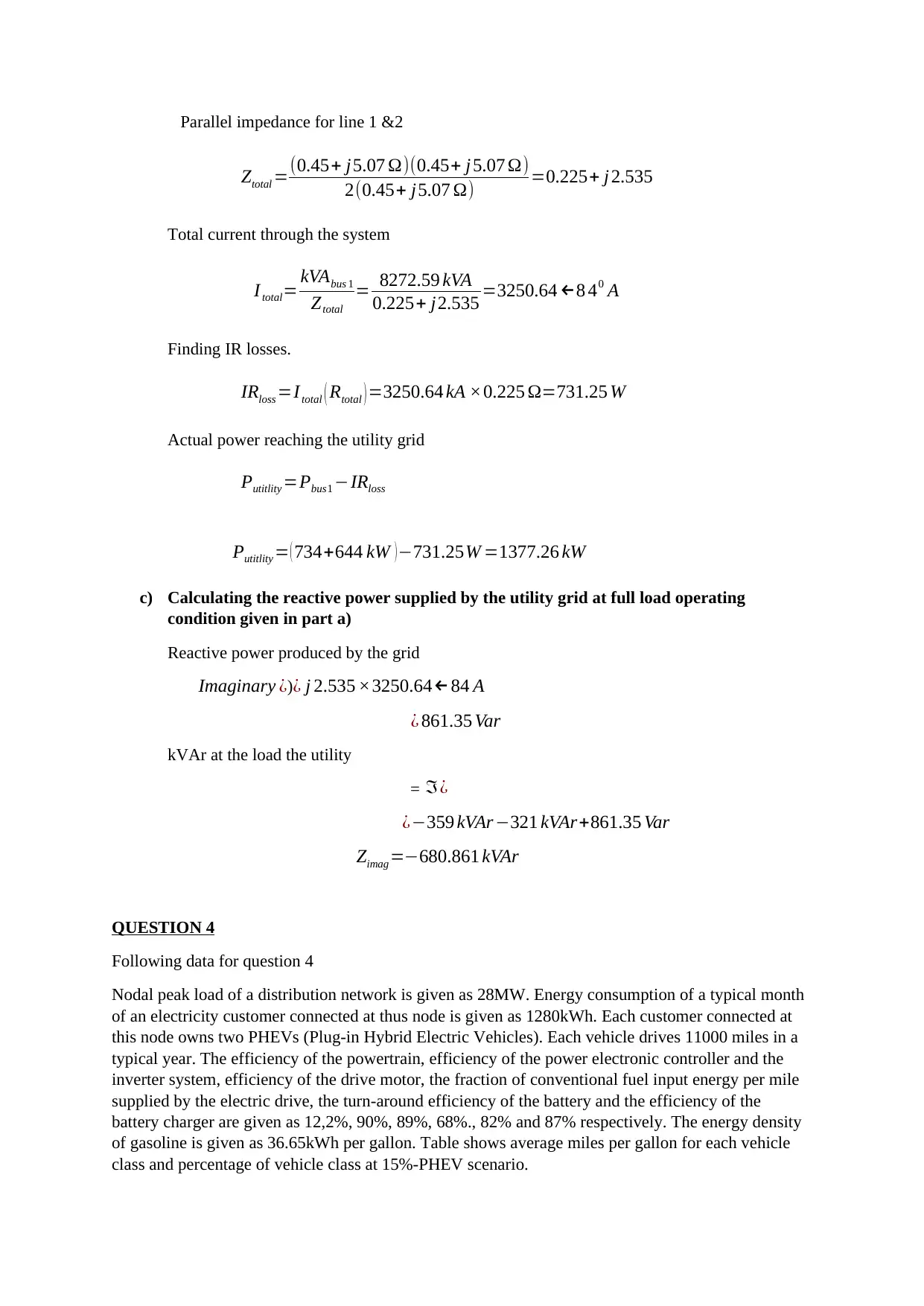
Parallel impedance for line 1 &2
Ztotal =(0.45+ j5.07 Ω)(0.45+ j 5.07 Ω)
2(0.45+ j5.07 Ω) =0.225+ j 2.535
Total current through the system
I total= kVAbus 1
Ztotal
= 8272.59 kVA
0.225+ j2.535 =3250.64 ←8 40 A
Finding IR losses.
IRloss =Itotal ( Rtotal ) =3250.64 kA ×0.225 Ω=731.25 W
Actual power reaching the utility grid
Putitlity =Pbus1 −IRloss
Putitlity = ( 734+644 kW ) −731.25W =1377.26 kW
c) Calculating the reactive power supplied by the utility grid at full load operating
condition given in part a)
Reactive power produced by the grid
Imaginary ¿)¿ j 2.535 ×3250.64← 84 A
¿ 861.35 Var
kVAr at the load the utility
= ℑ¿
¿−359 kVAr−321 kVAr+861.35 Var
Zimag=−680.861 kVAr
QUESTION 4
Following data for question 4
Nodal peak load of a distribution network is given as 28MW. Energy consumption of a typical month
of an electricity customer connected at thus node is given as 1280kWh. Each customer connected at
this node owns two PHEVs (Plug-in Hybrid Electric Vehicles). Each vehicle drives 11000 miles in a
typical year. The efficiency of the powertrain, efficiency of the power electronic controller and the
inverter system, efficiency of the drive motor, the fraction of conventional fuel input energy per mile
supplied by the electric drive, the turn-around efficiency of the battery and the efficiency of the
battery charger are given as 12,2%, 90%, 89%, 68%., 82% and 87% respectively. The energy density
of gasoline is given as 36.65kWh per gallon. Table shows average miles per gallon for each vehicle
class and percentage of vehicle class at 15%-PHEV scenario.
⊘ This is a preview!⊘
Do you want full access?
Subscribe today to unlock all pages.
Trusted by 1+ million students worldwide
1 out of 25
Your All-in-One AI-Powered Toolkit for Academic Success.
+13062052269
info@desklib.com
Available 24*7 on WhatsApp / Email
![[object Object]](/_next/static/media/star-bottom.7253800d.svg)
Unlock your academic potential
Copyright © 2020–2026 A2Z Services. All Rights Reserved. Developed and managed by ZUCOL.