Capacitor Analysis and Circuit Behavior in Electrical Engineering
VerifiedAdded on 2022/11/19
|34
|2731
|493
Homework Assignment
AI Summary
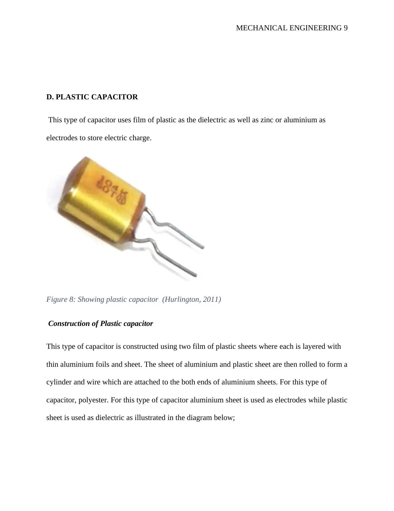
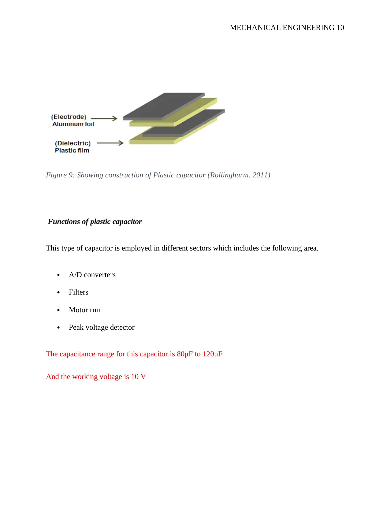
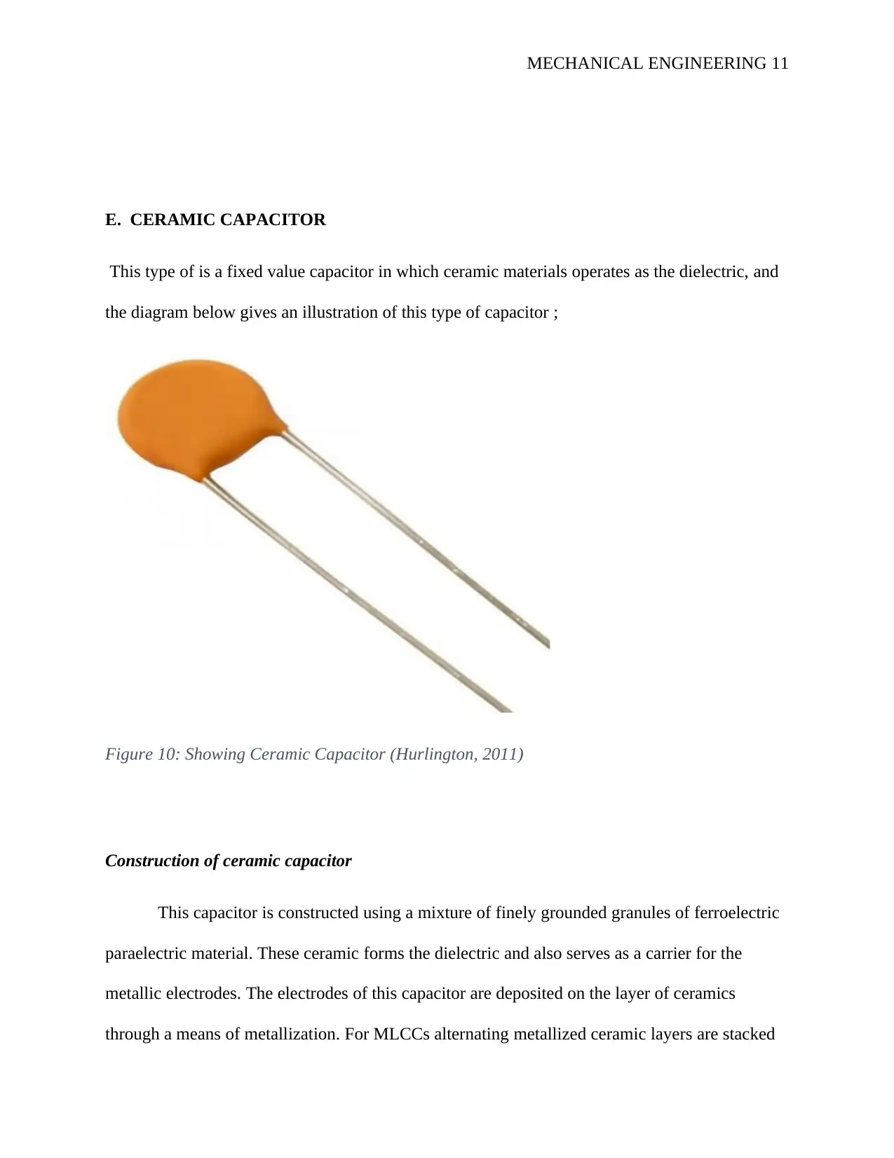
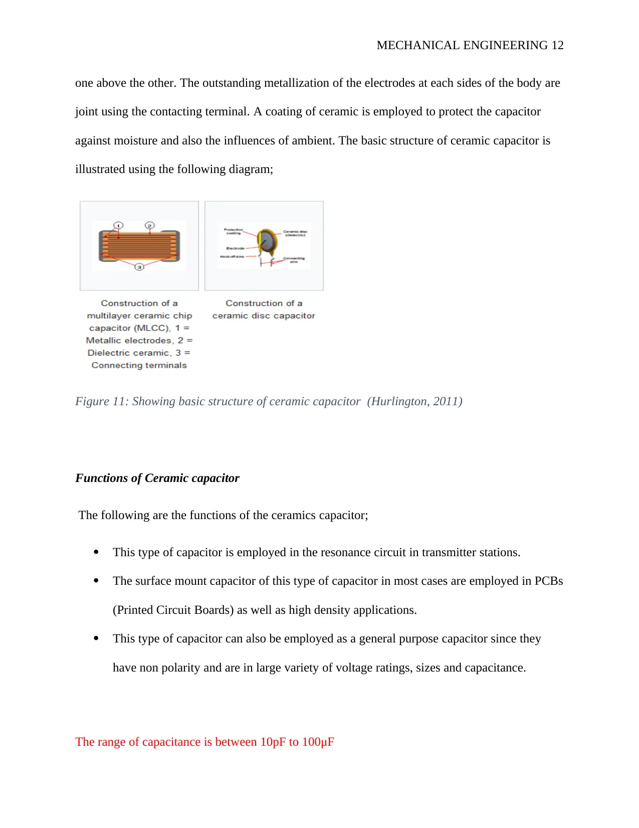
This assignment provides a comprehensive overview of various capacitor types, including electrolytic, mica, paper, plastic, ceramic, and variable capacitors, detailing their construction, functions, and applications. The assignment further explores the charging and discharging behavior of capacitors, presenting experimental data and graphs illustrating the relationship between voltage, current, and time constants. The analysis includes calculations for time constants and presents tables summarizing voltage and current values during charging and discharging phases. The document highlights the exponential relationship between charging current and decaying voltage during discharge, providing a detailed understanding of capacitor behavior in electrical circuits. The assignment also includes the assignment brief, which provides the context of the assignment and the requirements of the assignment.

MECHANICAL ENGINEERING 1
MECHANICAL ENGINEERING
By Name
Course
Instructor
Institution
Location
Date
MECHANICAL ENGINEERING
By Name
Course
Instructor
Institution
Location
Date
Paraphrase This Document
Need a fresh take? Get an instant paraphrase of this document with our AI Paraphraser

MECHANICAL ENGINEERING 2
TASK 1
A. ELECTROLYTIC CAPACITOR
Electrolytic capacitor is that type which employs the use of an electrolyte to realize a
relatively higher capacitance as compared to other capacitors. As the name suggest this type uses
gel or liquid having higher concentration of ions. This type of capacitor can be illustrated using
the following diagram;
Figure 1: Showing electrolytic capacitor (Rollinghurm, 2011).
Construction of electrolytic capacitor
Electrolytic capacitor is constructed by the use of two thin films of coils of aluminium, where
one layer is used to cover an oxide layer of an insulator (Rollinghurm, 2011). A soaked paper
sheet (soaked with electrolyte) is put in between the two plate and then wound around each
other, after this they are put into a can like tin. As shown in the diagram below;

MECHANICAL ENGINEERING 3
Figure 2: Showing Electrolytic capacitor internal structure (Rollinghurm, 2011).
During the manufacture of the aluminium electrolytic, the first step is to do etching of the
aluminium foil. This help to make the foils rougher to help increase the surface area thus the
capacitance level which is gained in a particular area. The next step is to make the anode. This
involves chemically growing a thin layer of oxide of aluminium to the anode foil isolating it
from the cathode. The elements of capacitor is wound on a winding machine. There are three
separate layers formed which are paper separator, anode foil, cathode foil. The paper separator is
brought in and then wound together. This paper separator will help to prevent the two electrode
from sorting and well as touching the two terminals.
⊘ This is a preview!⊘
Do you want full access?
Subscribe today to unlock all pages.

Trusted by 1+ million students worldwide

MECHANICAL ENGINEERING 4
Figure 3: Showing electrolytic capacitor construction (Rollinghurm, 2011).
When the capacitor is wound it is fed with the electrolyte, this may be done through use of
pressure or just by immersion.
Functions of electrolytic capacitor
Electrolyte has several function of which some includes the below discussed, this type of
capacitor is employed to reduce the ripple effects. It reduces the fluctuations of the voltages
several filter gadgets. Electrolytic capacitor can also be used to input and output the signals in
filters when the DC signal used is weak with AC components. Electrolytic capacitors are also
used for signal coupling between the stages of amplifiers as well as to store energy in flash bulbs.
The range of capacitance is 37.6μF and 56.4μF.
The maximum voltage rating of 25 volts,
Paraphrase This Document
Need a fresh take? Get an instant paraphrase of this document with our AI Paraphraser

MECHANICAL ENGINEERING 5
B. MICA CAPACITOR
This type of capacitor is a silicate mineral which are in granite as well as other rocks. MICA is a
shiny naturally occurring silicate. This type of capacitor can be illustrated using the following
diagram;
Figure 4: Showing MICA capacitor (Rollinghurm, 2011). (Hurlington, 2011)
Construction of Mica capacitor
The mica construction is done using thin sheets of mica coated having a lean sheets of silver.
The layers of silver are secured and then electrons are put though because physical defects in
both layers, there are less air gap that may interfere with the accuracy of these mica capacitors.
In addition, these air gaps may initiate problems because of mechanical pressure and the value of
capacitance would change over some time. And this can be illustrated using the following
diagram;

MECHANICAL ENGINEERING 6
Figure 5: Showing construction of Mica Capacitor (Hurlington, 2011)
Silva mica capacitor is constructed through covering the silver directly on the outside of the mica
to cover the suitable capacitance. When the layers are collected, electrodes are put and then
assembly is encapsulated.
Functions of mica capacitor
The following are some of the functions of this type of capacitor;
RF Oscillators: For these applications, mica is used due to their low loss level make the Q of
the turned circuit to be improved. This will help in improving stability as well as reducing the
level of phase noise.
Filter: The low level loss of the mica capacitor will enhance higher Q filter to be used
Coupling and decoupling: These capacitors are employed in coupling and decoupling since
they can withstand higher voltages.
The range of mica capacitance is between 20 pF and 10 μF.
The range of mica capacitor voltages between is between 100 and 1000 volts.
⊘ This is a preview!⊘
Do you want full access?
Subscribe today to unlock all pages.

Trusted by 1+ million students worldwide

MECHANICAL ENGINEERING 7
C. PAPER CAPACITOR
For this type of capacitor, the dielectric which is put between the plates is a paper. Here the
alternate aluminium and paper sheet form a stack and it generates more capacitance as compared
to a single sheet.
Construction of paper capacitor.
The paper sheet here is covered or soaked in wax or oil, this help to protect the capacitor from
the harmful surrounding environment (Hurlington, 2011). This capacitor is made through taking
two or several aluminium sheet and putting a paper in between the aluminium sheet. Therefore
the paper put in between the aluminium sheet operate like a dielectric while the aluminium acts
like electrodes as illustrated in the diagram below;
Figure 6: Showing construction of paper capacitor (Hurlington, 2011)
Since a paper is a poor conductor of electricity it won´t allow the flow of electric current or even
charges between the two sheets of aluminium. Nevertheless, the paper sheet allows electric field
to flow through it. Thus the sheet of paper put in between the aluminium acts as a barrier for
dielectric current. This is illustrated in the diagram below;
Paraphrase This Document
Need a fresh take? Get an instant paraphrase of this document with our AI Paraphraser

MECHANICAL ENGINEERING 8
Figure 7: Showing arrangement of paper sheet and aluminium in paper capacitor (Hurlington,
2011)
Functions of paper capacitor
Paper capacitors are employed in signal coupling, this is due to the fact that capacitor pass AC
and block DC at the same time. Therefore this type of capacitor can be employed to separate the
DC and AC components of signal. And this is what is known as signal coupling. This capacitor
can as well be employed as high pass filter and low pass filter.
The capacitance range of the paper capacitor is from 0.001 to 2.000micro farad and the voltage is
very high which is up to 2000V.

MECHANICAL ENGINEERING 9
D. PLASTIC CAPACITOR
This type of capacitor uses film of plastic as the dielectric as well as zinc or aluminium as
electrodes to store electric charge.
Figure 8: Showing plastic capacitor (Hurlington, 2011)
Construction of Plastic capacitor
This type of capacitor is constructed using two film of plastic sheets where each is layered with
thin aluminium foils and sheet. The sheet of aluminium and plastic sheet are then rolled to form a
cylinder and wire which are attached to the both ends of aluminium sheets. For this type of
capacitor, polyester. For this type of capacitor aluminium sheet is used as electrodes while plastic
sheet is used as dielectric as illustrated in the diagram below;
⊘ This is a preview!⊘
Do you want full access?
Subscribe today to unlock all pages.

Trusted by 1+ million students worldwide

MECHANICAL ENGINEERING 10
Figure 9: Showing construction of Plastic capacitor (Rollinghurm, 2011)
Functions of plastic capacitor
This type of capacitor is employed in different sectors which includes the following area.
A/D converters
Filters
Motor run
Peak voltage detector
The capacitance range for this capacitor is 80μF to 120μF
And the working voltage is 10 V
Paraphrase This Document
Need a fresh take? Get an instant paraphrase of this document with our AI Paraphraser

MECHANICAL ENGINEERING 11
E. CERAMIC CAPACITOR
This type of is a fixed value capacitor in which ceramic materials operates as the dielectric, and
the diagram below gives an illustration of this type of capacitor ;
Figure 10: Showing Ceramic Capacitor (Hurlington, 2011)
Construction of ceramic capacitor
This capacitor is constructed using a mixture of finely grounded granules of ferroelectric
paraelectric material. These ceramic forms the dielectric and also serves as a carrier for the
metallic electrodes. The electrodes of this capacitor are deposited on the layer of ceramics
through a means of metallization. For MLCCs alternating metallized ceramic layers are stacked

MECHANICAL ENGINEERING 12
one above the other. The outstanding metallization of the electrodes at each sides of the body are
joint using the contacting terminal. A coating of ceramic is employed to protect the capacitor
against moisture and also the influences of ambient. The basic structure of ceramic capacitor is
illustrated using the following diagram;
Figure 11: Showing basic structure of ceramic capacitor (Hurlington, 2011)
Functions of Ceramic capacitor
The following are the functions of the ceramics capacitor;
This type of capacitor is employed in the resonance circuit in transmitter stations.
The surface mount capacitor of this type of capacitor in most cases are employed in PCBs
(Printed Circuit Boards) as well as high density applications.
This type of capacitor can also be employed as a general purpose capacitor since they
have non polarity and are in large variety of voltage ratings, sizes and capacitance.
The range of capacitance is between 10pF to 100μF
⊘ This is a preview!⊘
Do you want full access?
Subscribe today to unlock all pages.

Trusted by 1+ million students worldwide
1 out of 34

Your All-in-One AI-Powered Toolkit for Academic Success.
+13062052269
info@desklib.com
Available 24*7 on WhatsApp / Email
Unlock your academic potential
Copyright © 2020–2025 A2Z Services. All Rights Reserved. Developed and managed by ZUCOL.