Electrical Engineering Assignment: Drawings, Diagrams, Regulations
VerifiedAdded on 2024/06/10
|23
|4542
|175
Homework Assignment
AI Summary
This assignment solution covers a range of topics in electrical engineering, starting with architectural and electrical drawings, including site plans and floor plans. It delves into circuit and wiring diagrams, explaining their purpose, conventions, and features, along with Australian standard symbols. The solution also addresses building construction drawings, listing various building types and components. Furthermore, it discusses regulations for electrical work, standards philosophy, and the format and content of job specifications. The document includes answers to specific questions related to these topics, providing a comprehensive overview of essential concepts in electrical technology. Desklib offers this and many other solved assignments for students.
Table of Contents
TASK 1 Architectural drawing................................................................................................................2
Task 2 - Electrical drawings....................................................................................................................5
Task 3 - Circuit diagrams........................................................................................................................8
Task 4 - Wiring diagrams.....................................................................................................................10
Task 5 - Building construction drawings and diagrams........................................................................12
Task 6 - Regulation for undertaking electrical work............................................................................14
Task 7 - Standards philosophy and format..........................................................................................15
Task 8 - Purpose, format and content of typical job specifications.....................................................18
Questions............................................................................................................................................19
1...........................................................................................................................................................19
2...........................................................................................................................................................19
3...........................................................................................................................................................19
4...........................................................................................................................................................20
5...........................................................................................................................................................20
6...........................................................................................................................................................20
7...........................................................................................................................................................20
8...........................................................................................................................................................20
9...........................................................................................................................................................21
10.........................................................................................................................................................21
11.........................................................................................................................................................21
12.........................................................................................................................................................21
13.........................................................................................................................................................21
14.........................................................................................................................................................22
Paraphrase This Document
Need a fresh take? Get an instant paraphrase of this document with our AI Paraphraser
Written activity
TASK 1 Architectural drawing
1. What information should be included in a site plan?
Information that must be included in the site plan is;
All the land features ad characteristics
Structures
Land and building total area
Property structure and boundary distance
Amenities
Symbols
Scale
Site land contours
Drawings
2. What information should be included on a floor plan?
Floor plan is a standard and structures scale for building drawing plan. Following information needs
to be included in the floor plan that is;
Windows and doors
Scale
Electrical fittings
External and internal wall dimensions
Appliances
Standard symbols
Cable routes
Conventions of standard drawings.
3. When using an architectural floor plan in order to determine the location and
requirements for the power and lighting or communications / audio/ video layouts
required in a domestic installation, what will you need to take into consideration?
Architecture floor plan is necessary to use for determining various aspects like lighting, power, video,
communication and audio layout which is needed for complete installation of domestic wiring.
Following are the necessary aspects that needs to be taken into consideration that are;
Scale
Each connection wiring requirements
Floor plan detail
Each product and item standard symbol
Each connection circuit requirements
4. Discuss the following in regards to site plans:
a. Service point
On each floor plan there is a point of service which is used for depicting the point exact location
where the wiring system of consumer and wholesaler provider of electrical meets.
b. Consumers mains
Consumer’s mains as the name suggest is the chief supply point for the consumers that are drawn
from the service point drawing.
c. Main switchboard
The switchboard incorporates entire electrical cables and consumer mains that run around or within
the building area. Switchboard incorporates;
Safety switches
Main power connection
Main fuse
Buildings entire mainline and backline connections
Consumption measuring device.
d. Distribution boards
It is the domestic component of wiring system that separates the main power supply in distinct
circuits. It is generally present as main switchboard at some location in the building.
e. Builder’s supplies
In some specific case or situation builders needs an electrical supply range for utilizing the running
power of the property. Due to this purpose before the completion of property construction of wiring
in the building or property is completed.
5. What is the most common scale used for floor plans? What does it represent?
Site or architectural drawings need to be done on scale. Some standard fractions are important for
floor plans that are 1:50 and 1:100.
1:100- also known as 1/100th which defines that the definite item would be 100 times
greater than the floor plan size.
1:50- also known as 1/50th which defines that the definite item would be 50 times greater
than the floor plan size.
Widely used scale is 1:100scale for the floor plans as it is the most standard format.
⊘ This is a preview!⊘
Do you want full access?
Subscribe today to unlock all pages.
Trusted by 1+ million students worldwide
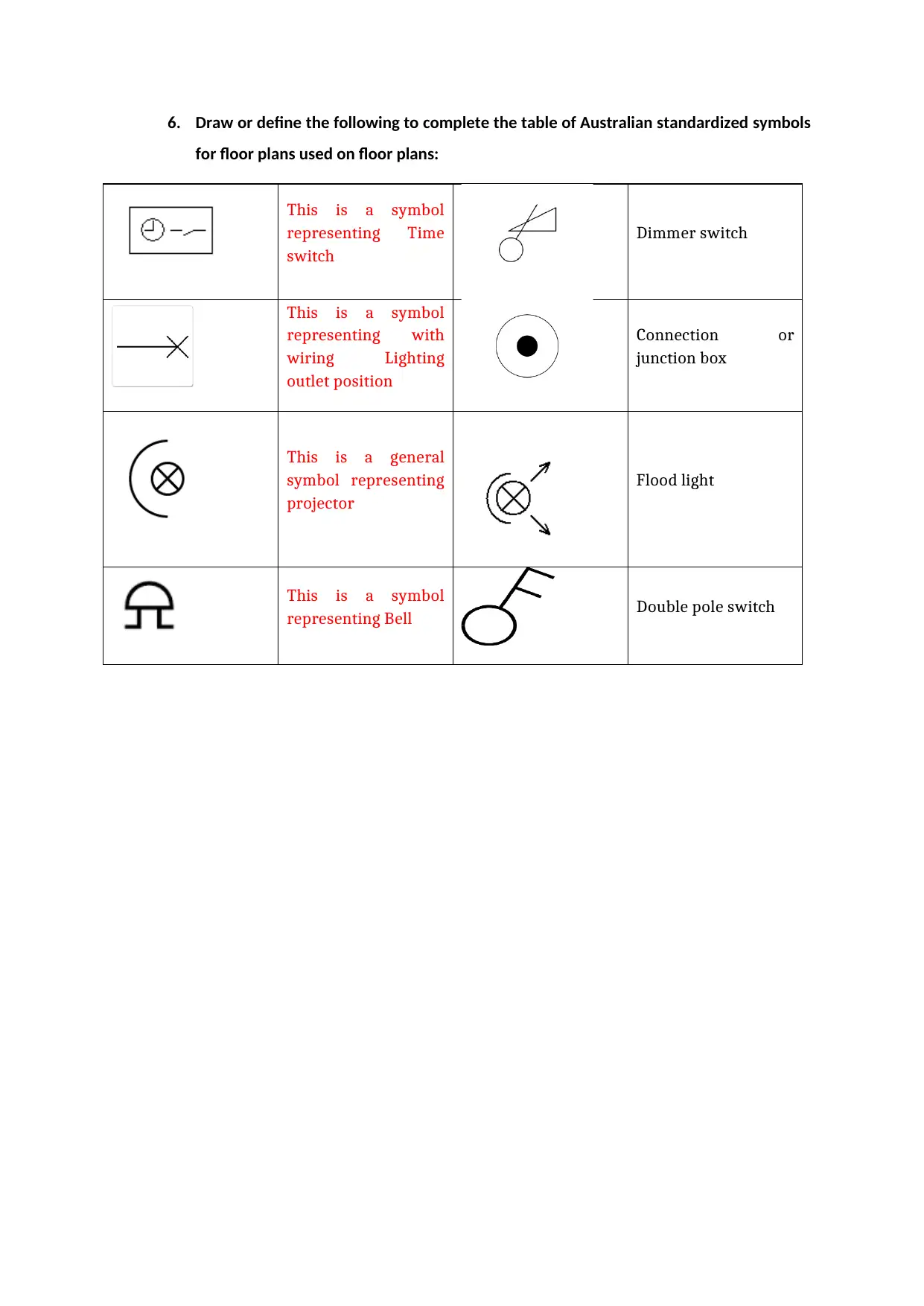
6. Draw or define the following to complete the table of Australian standardized symbols
for floor plans used on floor plans:
This is a symbol
representing Time
switch
Dimmer switch
This is a symbol
representing with
wiring Lighting
outlet position
Connection or
junction box
This is a general
symbol representing
projector
Flood light
This is a symbol
representing Bell Double pole switch
Paraphrase This Document
Need a fresh take? Get an instant paraphrase of this document with our AI Paraphraser
Task 2 - Electrical drawings
1. Describe the purpose of each of the following types of electrical drawings:
a. Block diagrams
It is a components made from block series that makes the electric circuit or project. it is mainly used
for the;
Planning
Communication
Design and
Installation
b. Circuit diagrams
It is a symbol or pictorial constructed drawings or diagrams made from standard designs, layouts and
formats of all elements that make the electrical circuit. It is mainly used for following purpose;
Installation
Planning
Design
Troubleshooting and
Communication
c. Wiring diagrams
It is made from the standard lines and symbol range that explains each components and connections
needed for device or building wiring. It is mainly used for following purpose that is;
Installation
Communication
Troubleshooting
Design and
planning
d. Ladder diagrams
It is ladder due to its construction shape. Rail at the left is component carrying current and Two
vertical poles denotes the power source and the right rail is grounding. It is mainly used for the
following purpose that is;
Troubleshooting
Power circuit understanding
Corrections and
Maintenance
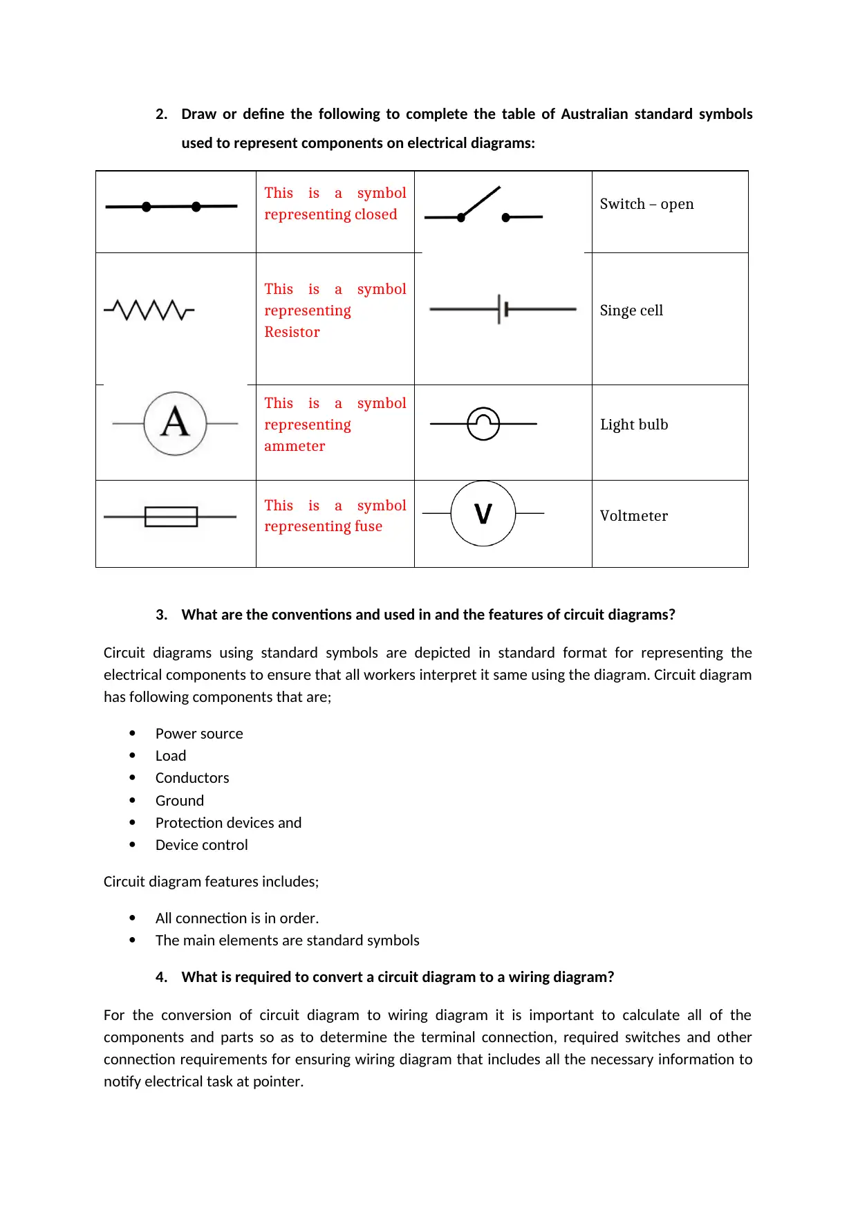
2. Draw or define the following to complete the table of Australian standard symbols
used to represent components on electrical diagrams:
This is a symbol
representing closed Switch – open
This is a symbol
representing
Resistor
Singe cell
This is a symbol
representing
ammeter
Light bulb
This is a symbol
representing fuse Voltmeter
3. What are the conventions and used in and the features of circuit diagrams?
Circuit diagrams using standard symbols are depicted in standard format for representing the
electrical components to ensure that all workers interpret it same using the diagram. Circuit diagram
has following components that are;
Power source
Load
Conductors
Ground
Protection devices and
Device control
Circuit diagram features includes;
All connection is in order.
The main elements are standard symbols
4. What is required to convert a circuit diagram to a wiring diagram?
For the conversion of circuit diagram to wiring diagram it is important to calculate all of the
components and parts so as to determine the terminal connection, required switches and other
connection requirements for ensuring wiring diagram that includes all the necessary information to
notify electrical task at pointer.
⊘ This is a preview!⊘
Do you want full access?
Subscribe today to unlock all pages.
Trusted by 1+ million students worldwide
5. What is a cable schedule?
It is a file that incorporates the list of cables needed to complete the wiring task, specific circuit and
installation. It is mainly used for the following purpose;
Carrying the installation procedure planning
Material and resource selection
Length determination approximation.
6. What information will be listed on the cable schedule regarding each of the cables
included?
For the cables there are following information which is listed in the cable scheduler that are;
Each cable type
Each cable length
Each cable size and gland type
Size of cable
Serial number of cable
Each cable details like source, destination and end point.
7. What steps are involved in developing a cable schedule for a given installation?
When the cable schedule is developed for the specific installation it is required to follow some
important steps that are;
Identification of all required cable routes and access points.
Entire Cable list
Identifying the cable needed for different connections.
Entire cable specification list.
All connections requirements are identified
Neat and easy list of table that contains the above mentioned information.
Paraphrase This Document
Need a fresh take? Get an instant paraphrase of this document with our AI Paraphraser
Task 3 - Circuit diagrams
1. What is the purpose of circuit diagrams in the electro technology industry?
Circuit diagram has several purposes to demonstrate electrical workers in the electro technology
industry that are;
Circuit basic components
Set up order
Circuits are used to;
Calculate circuits
Resource identification
Troubleshoot circuit
Safety analysis to be conducted
Electrical work needs to be plan
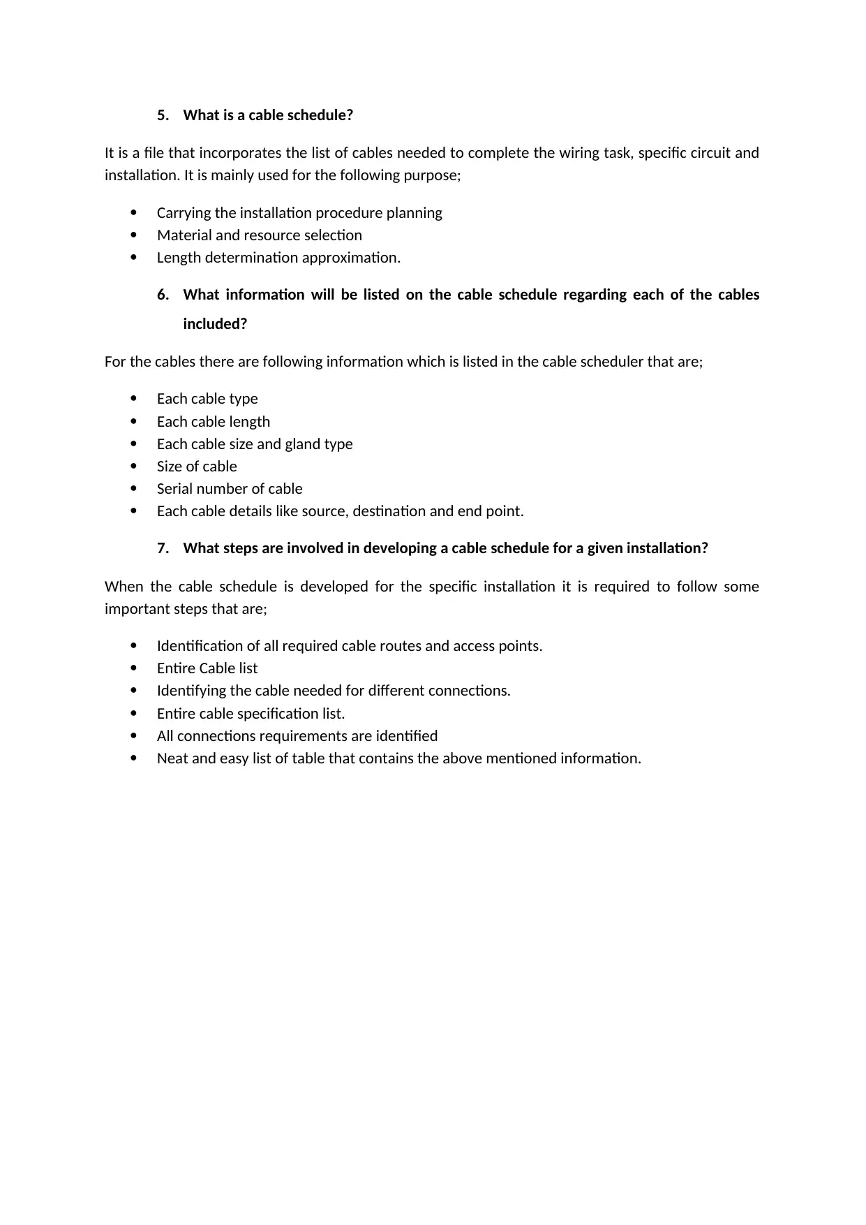
2. Draw and label a basic circuit diagram showing at least three components
3. What are the steps that need to be conducted in order to develop a switching chart for
use when planning and conducting electrical work?
Developing the switching chart is the necessary procedure to identify different types of terminals.
The following steps are required to be followed for developing the switching g chart while
conducting and planning the electrical work;
Positions of entire potential switching needs to be determined and documented.
Entire switch need to be determined and documented.
For ensuring the possible position of switch and combination of terminals a meter is used.
Entire factors need to be placed in the columns.
4. What needs to be kept in mind when preparing to connect equipment using circuit
diagrams?
1. What is the purpose of circuit diagrams in the electro technology industry?
Circuit diagram has several purposes to demonstrate electrical workers in the electro technology
industry that are;
Circuit basic components
Set up order
Circuits are used to;
Calculate circuits
Resource identification
Troubleshoot circuit
Safety analysis to be conducted
Electrical work needs to be plan
2. Draw and label a basic circuit diagram showing at least three components
3. What are the steps that need to be conducted in order to develop a switching chart for
use when planning and conducting electrical work?
Developing the switching chart is the necessary procedure to identify different types of terminals.
The following steps are required to be followed for developing the switching g chart while
conducting and planning the electrical work;
Positions of entire potential switching needs to be determined and documented.
Entire switch need to be determined and documented.
For ensuring the possible position of switch and combination of terminals a meter is used.
Entire factors need to be placed in the columns.
4. What needs to be kept in mind when preparing to connect equipment using circuit
diagrams?

It is viable to interface equip the usage of circuit plots yet it could be crucial to manual an extent of
other facts and play out an volume of tests and estimations too that allows to ensure that maximum
of the requirements of the circuit are met as circuit graphs won't show each and every terminal
affiliation and purposes of intrigue.
other facts and play out an volume of tests and estimations too that allows to ensure that maximum
of the requirements of the circuit are met as circuit graphs won't show each and every terminal
affiliation and purposes of intrigue.
⊘ This is a preview!⊘
Do you want full access?
Subscribe today to unlock all pages.
Trusted by 1+ million students worldwide
Task 4 - Wiring diagrams
1. What is the purpose of wiring diagrams in the electro technology industry?
The purpose of wiring circuits is to provide easy graphical presentation of entire electric and circuit
installations. Following are the purpose of wiring diagrams;
It helps in plans for depicting lighting
It helps in depicting plans for house wiring
It helps in depicting plans for system wiring
It helps in depicting plans for device wiring.
2. What conventions are used in wiring diagrams?
Wiring diagrams are depicted through the standard symbols in standard format for representing the
electrical parts for ensuring that all workers are interpreting same using the diagrams.
3. What are the features of wiring diagrams?
Wiring diagrams have several features that are;
Relationship among the connections
Wiring plan basic structure
All connections basic symbols
Technical connections
4. What can sketch basic wiring assist with?
Many workers of the electrical will do freehand drawing of the wiring diagram for gaining the
graphical understanding of system and electrical plan they are working with;
Sketching of basic wiring diagrams;
Needs to be basic
It can assist in developing and planning of the wiring systems
Troubleshooting can be assisted.
It can be done through standard symbols.
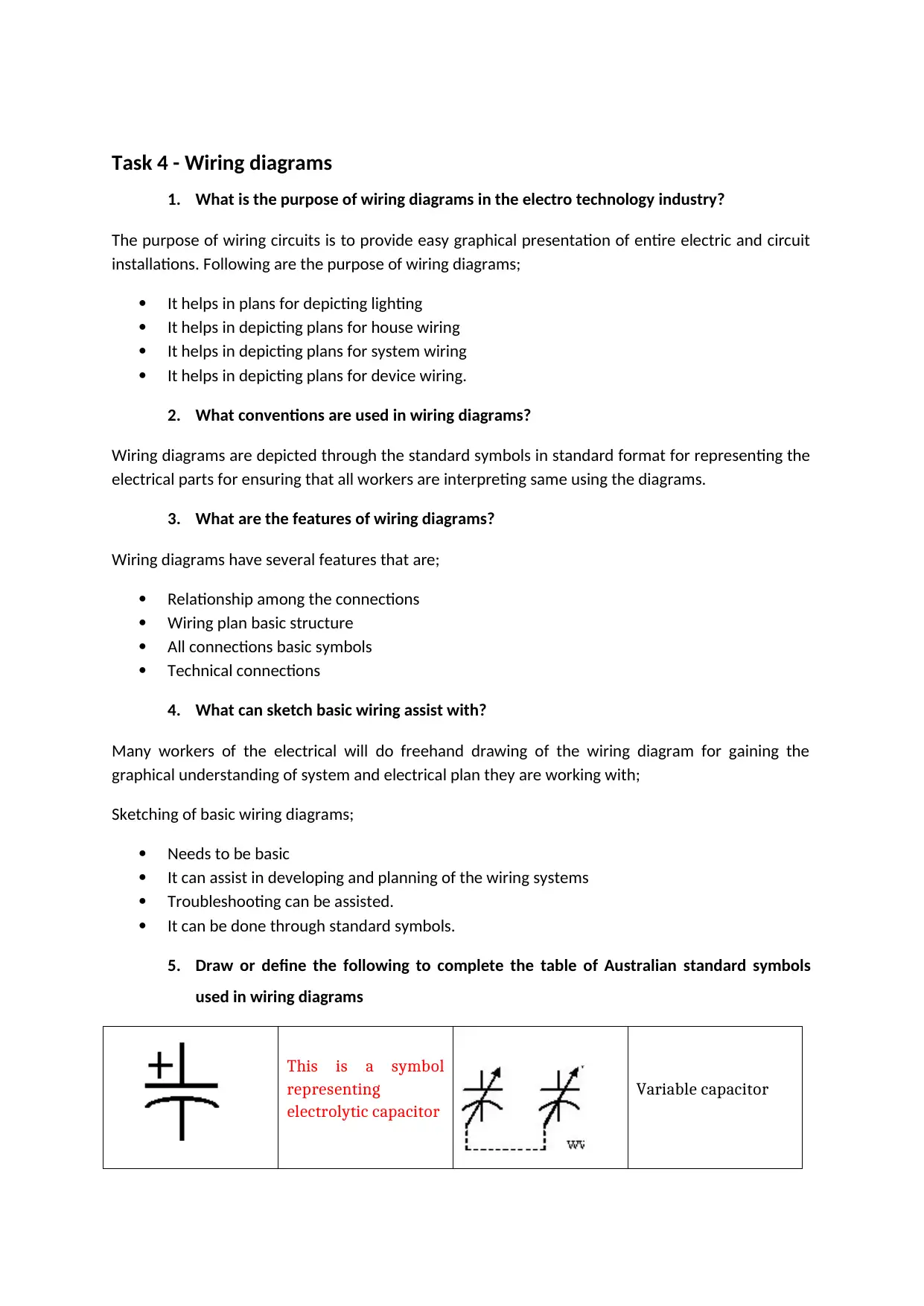
5. Draw or define the following to complete the table of Australian standard symbols
used in wiring diagrams
This is a symbol
representing
electrolytic capacitor
Variable capacitor
1. What is the purpose of wiring diagrams in the electro technology industry?
The purpose of wiring circuits is to provide easy graphical presentation of entire electric and circuit
installations. Following are the purpose of wiring diagrams;
It helps in plans for depicting lighting
It helps in depicting plans for house wiring
It helps in depicting plans for system wiring
It helps in depicting plans for device wiring.
2. What conventions are used in wiring diagrams?
Wiring diagrams are depicted through the standard symbols in standard format for representing the
electrical parts for ensuring that all workers are interpreting same using the diagrams.
3. What are the features of wiring diagrams?
Wiring diagrams have several features that are;
Relationship among the connections
Wiring plan basic structure
All connections basic symbols
Technical connections
4. What can sketch basic wiring assist with?
Many workers of the electrical will do freehand drawing of the wiring diagram for gaining the
graphical understanding of system and electrical plan they are working with;
Sketching of basic wiring diagrams;
Needs to be basic
It can assist in developing and planning of the wiring systems
Troubleshooting can be assisted.
It can be done through standard symbols.
5. Draw or define the following to complete the table of Australian standard symbols
used in wiring diagrams
This is a symbol
representing
electrolytic capacitor
Variable capacitor
Paraphrase This Document
Need a fresh take? Get an instant paraphrase of this document with our AI Paraphraser

This is a symbol
representing iron
core transformers
Headphones (double)
This is a symbol
representing general
antenna
Telegraph key
representing iron
core transformers
Headphones (double)
This is a symbol
representing general
antenna
Telegraph key
Task 5 - Building construction drawings and diagrams
1. List and briefly describe the four building types that electrical work may need to be
conducted within.
There are several building types that is needed by electrical work that are;
Timber frame: it is a building made from the frame of wooden components which is connected
professionally together such that it provides a building that structurally sound which is externally
and internally cladded for completion.
Brick veneer: it is the timber frame arrangement which is cladded through a non-structured plane
brick wall. It is the most basic type of building.
Double brick: it is the strongest and well-insulated type of building which is made from the two
strong brick structured walls along with left cavity among them.
Metal frame: it is the strongest and constructed through the skeleton frame made by metal by
arranging the steel columns vertically and metal beams horizontally in cross section direction to
construct a grid arrangement. Using the metal frame skyscraper are made as using this building type
tall buildings can be constructed.
2. List two examples of each of the following:
a. Footings
Examples of footings are stepped and stump pad.
b. Floors
Examples of floors are platform floors and cut-in floors.
c. External walls
Examples of external walls are brick veneer and metal cladding
d. Roofs
Examples of roofs are gable and hip.
e. Interior walls
Examples of interior walls are tiles and mortar.
3. List and describe two types of typical cable routes through buildings, structures and
premises.
Two types of typical cables are backbone cabling and Entrance facilities
⊘ This is a preview!⊘
Do you want full access?
Subscribe today to unlock all pages.
Trusted by 1+ million students worldwide
1 out of 23
Related Documents


Your All-in-One AI-Powered Toolkit for Academic Success.
+13062052269
info@desklib.com
Available 24*7 on WhatsApp / Email
![[object Object]](/_next/static/media/star-bottom.7253800d.svg)
Unlock your academic potential
Copyright © 2020–2026 A2Z Services. All Rights Reserved. Developed and managed by ZUCOL.