Comprehensive Report on Synchronous Machines, FACTS, and HVDC Systems

Verified

Added on  2022/11/18

|3
|535
|313
Report
AI Summary
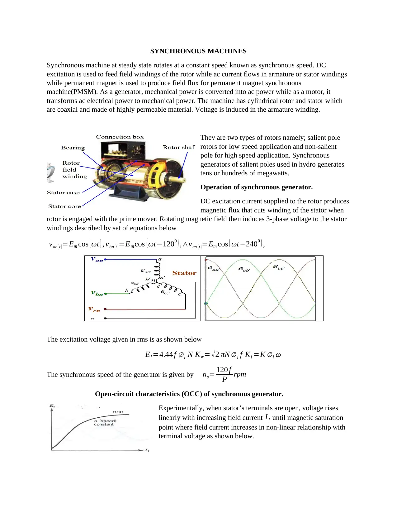
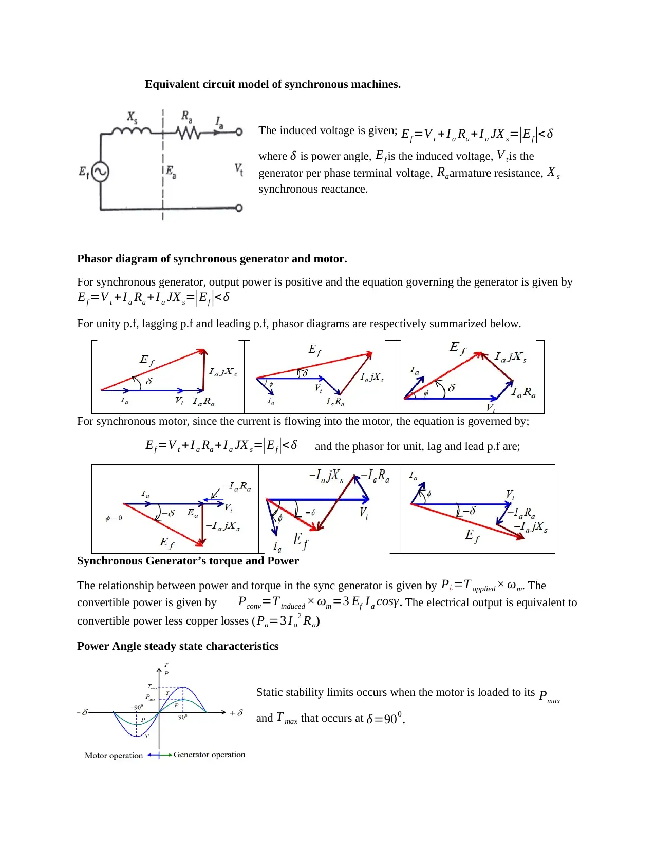
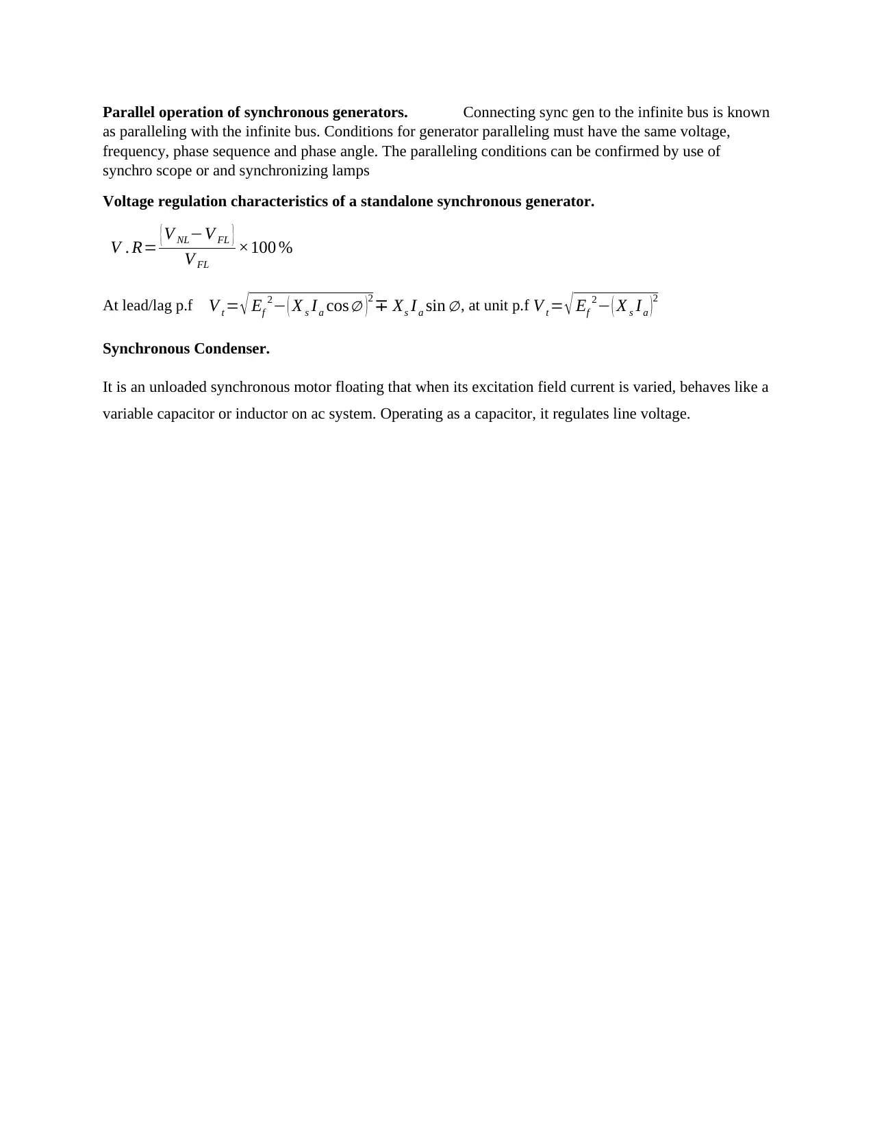
This report provides a comprehensive overview of synchronous machines, FACTS (Flexible AC Transmission Systems) devices, and HVDC (High Voltage Direct Current) systems. It begins by explaining the operational principles of synchronous machines, including their use as generators and motors, detailing their rotor types, and discussing their equivalent circuit models, phasor diagrams, and torque-power relationships. The report also covers generator paralleling and voltage regulation characteristics. The second part delves into FACTS devices, such as SVC (Static Var Compensator) and STATCOM (Static Synchronous Compensator), highlighting their role in enhancing the security, capacity, and flexibility of power transmission networks. Finally, the report introduces HVDC systems, which are used for long-distance power transmission and grid interconnection. The report integrates concepts from the provided assignment brief and supporting documents on AC transmission lines and power flow control, providing a holistic understanding of power system components and control strategies.
Document Page
SYNCHRONOUS MACHINES
Synchronous machine at steady state rotates at a constant speed known as synchronous speed. DC
excitation is used to feed field windings of the rotor while ac current flows in armature or stator windings
while permanent magnet is used to produce field flux for permanent magnet synchronous
machine(PMSM). As a generator, mechanical power is converted into ac power while as a motor, it
transforms ac electrical power to mechanical power. The machine has cylindrical rotor and stator which
are coaxial and made of highly permeable material. Voltage is induced in the armature winding.
They are two types of rotors namely; salient pole
rotors for low speed application and non-salient
pole for high speed application. Synchronous
generators of salient poles used in hydro generates
tens or hundreds of megawatts.
Operation of synchronous generator.
DC excitation current supplied to the rotor produces
magnetic flux that cuts winding of the stator when
rotor is engaged with the prime mover. Rotating magnetic field then induces 3-phase voltage to the stator
windings described by set of equations below
van ( t ) =Em cos ( ωt ) , vbn ( t ) =Em cos ( ωt1200 ) ,vcn ( t ) =Em cos ( ωt2400 ) ,
The excitation voltage given in rms is as shown below
Ef =4.44 f f N Kw= 2 πN f f Kf =K f ω
The synchronous speed of the generator is given by ns= 120 f
P rpm
Open-circuit characteristics (OCC) of synchronous generator.
Experimentally, when stator’s terminals are open, voltage rises
linearly with increasing field current I f until magnetic saturation
point where field current increases in non-linear relationship with
terminal voltage as shown below.
tabler-icon-diamond-filled.svg

Paraphrase This Document

Need a fresh take? Get an instant paraphrase of this document with our AI Paraphraser
Document Page
Equivalent circuit model of synchronous machines.
The induced voltage is given; Ef =V t + Ia Ra + Ia JX s=|Ef |< δ
where δ is power angle, Ef is the induced voltage, V tis the
generator per phase terminal voltage, Raarmature resistance, X s
synchronous reactance.
Phasor diagram of synchronous generator and motor.
For synchronous generator, output power is positive and the equation governing the generator is given by
Ef =V t + Ia Ra +I a JX s=|Ef |< δ
For unity p.f, lagging p.f and leading p.f, phasor diagrams are respectively summarized below.
For synchronous motor, since the current is flowing into the motor, the equation is governed by;
Ef =V t +I a Ra +Ia JX s=|Ef |< δ and the phasor for unit, lag and lead p.f are;
Synchronous Generator’s torque and Power
The relationship between power and torque in the sync generator is given by P¿=T applied × ωm. The
convertible power is given by Pconv=T induced × ωm =3 Ef I a cosγ. The electrical output is equivalent to
convertible power less copper losses ( Pa=3 I a
2 Ra)
Power Angle steady state characteristics
Static stability limits occurs when the motor is loaded to its Pmax
and T max that occurs at δ=900 .
Document Page
Parallel operation of synchronous generators. Connecting sync gen to the infinite bus is known
as paralleling with the infinite bus. Conditions for generator paralleling must have the same voltage,
frequency, phase sequence and phase angle. The paralleling conditions can be confirmed by use of
synchro scope or and synchronizing lamps
Voltage regulation characteristics of a standalone synchronous generator.
V . R= {V NLV FL }
V FL
×100 %
At lead/lag p.f V t = Ef
2 ( X s Ia cos )2 Xs Ia sin , at unit p.f V t = Ef
2 ( X s Ia )2
Synchronous Condenser.
It is an unloaded synchronous motor floating that when its excitation field current is varied, behaves like a
variable capacitor or inductor on ac system. Operating as a capacitor, it regulates line voltage.
chevron_up_icon
1 out of 3
circle_padding
hide_on_mobile
zoom_out_icon
[object Object]