Report on Magnetism, Transformers, and Motor/Generators Analysis
VerifiedAdded on 2023/04/25
|18
|2517
|478
Report
AI Summary
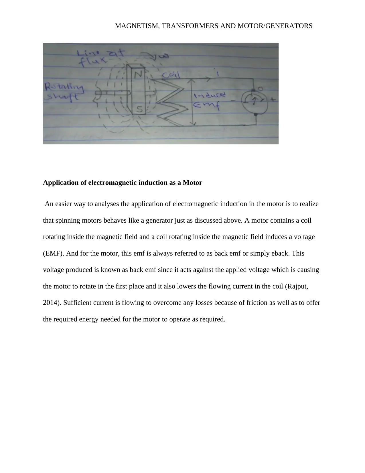
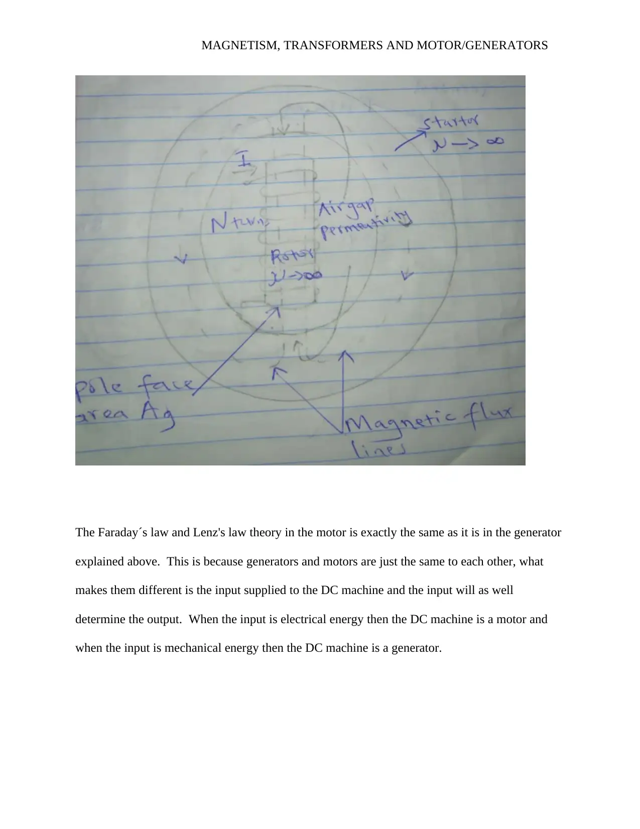
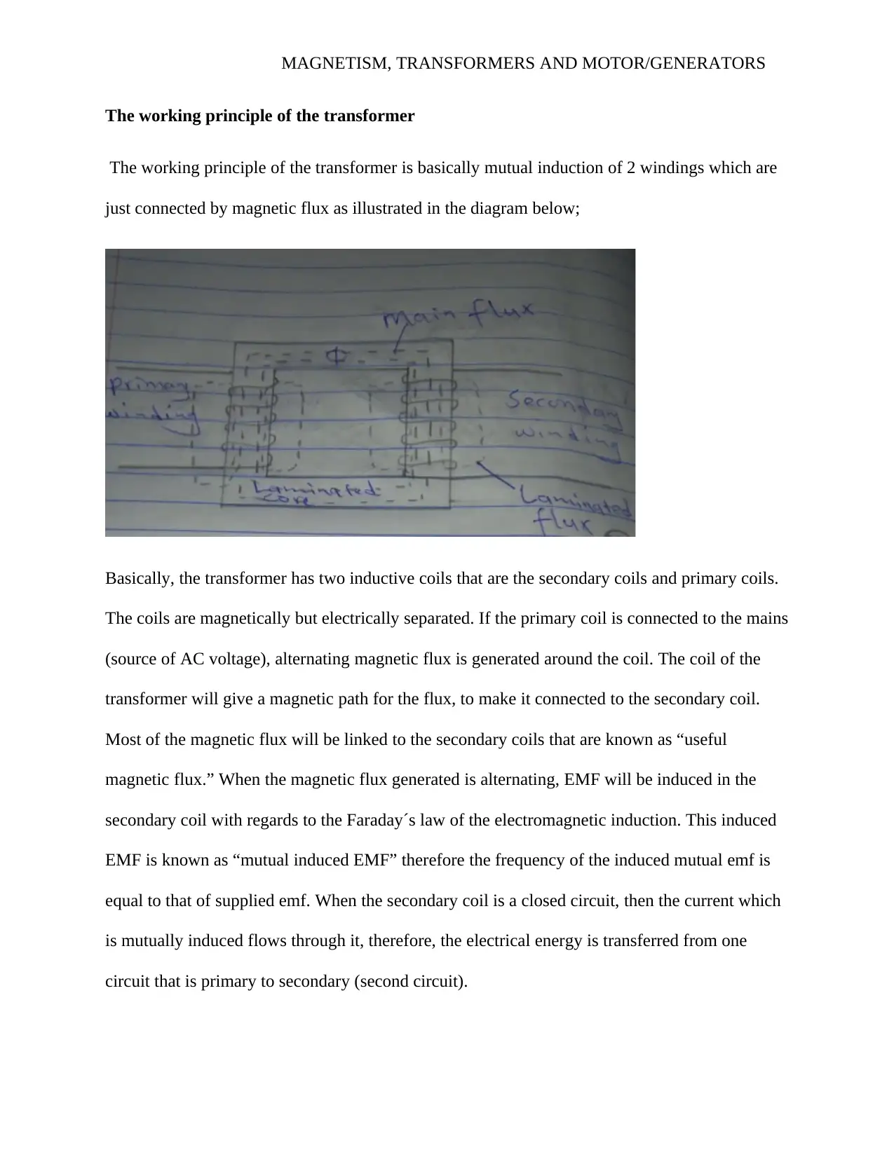
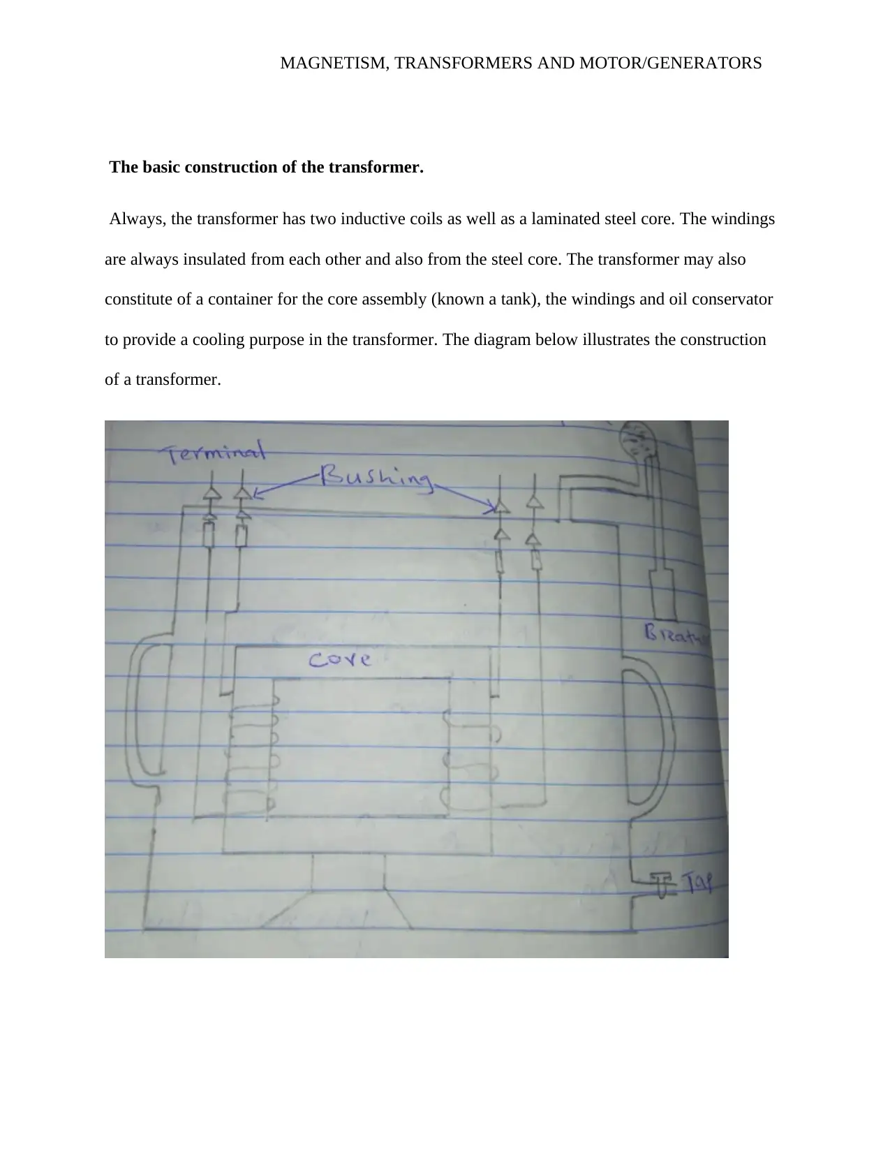
This report delves into the principles of magnetism, transformers, and motor/generators. It begins with an analysis of a single-phase generator, illustrating its components and operation, and includes calculations for induced EMF based on Faraday's law. The report then examines the components of a DC motor, explaining the function of each part, such as the battery, conductor loop, carbon brushes, commutator, field, conducting wire, and permanent magnet, and explores the impact of changing current and turns on motor speed. Furthermore, it investigates the application of electromagnetic induction in AC generators and motors, discussing Faraday's and Lenz's laws and the concept of back EMF. Finally, the report explains the working principle and construction of transformers, including mutual induction, primary and secondary coils, and the role of a laminated steel core, concluding with a brief overview of magnetism and magnetic fields. The report uses multiple sources to support its findings.

MAGNETISM, TRANSFORMERS AND MOTOR/GENERATORS
By Name
Course
Instructor
Institution
Location
Date
MAGNETISM, TRANSFORMERS AND MOTOR/GENERATORS
By Name
Course
Instructor
Institution
Location
Date
Paraphrase This Document
Need a fresh take? Get an instant paraphrase of this document with our AI Paraphraser

MAGNETISM, TRANSFORMERS AND MOTOR/GENERATORS
Induction motor and generator
TASK ONE
The diagram below illustrates a simple single phase generator, illustrating the permanent
magnets, load commutators among other key components of a generator (M.V.Bakshi, 2010).
When the above-drawn generator is operating, the operation waveform of EMF induced against
the angle cut between the magnetic flux and the conductor ∅ is illustrated in the diagram below;

MAGNETISM, TRANSFORMERS AND MOTOR/GENERATORS
From
EMF E = 2NBLvsin θ . . . . . . . . . . . . . . . . . . . . . . . . . . .. . . . . . . . . . . . . . . . . . . . . . . . . . . . . . .1
Where N is the number of turns, B is the magnetic flux density, L is the length of the magnet
(Krishnan, 2011). And v is the velocity.
N= 350
B= 1.75 T
L= 0.095 m
Speed = 103 RPM
V= ( 103
6 ×2 πrdas/s ) ( 0.0 65
6 )
⊘ This is a preview!⊘
Do you want full access?
Subscribe today to unlock all pages.

Trusted by 1+ million students worldwide

MAGNETISM, TRANSFORMERS AND MOTOR/GENERATORS
V= 10.787 × 0.0325
V = 0.3507m/s
For the maximum EMF induced θ=900 for which the sin is 1 (Oatley, 2012). Therefore the EMF
maximum is obtain as below using equation1 above;
E= 2NBLvsin θ
E= 2× 3 50×1.75×0.0950×0.3 507×1
E= 40.8127V
Part six
Part A: Battery
The battery is used to provide electrical energy as well as the current which will flow and cut the
magnetic field which will, in turn, induce a motion of the motor given in the diagram (Sahay,
2014).
Part B: Conductor loop
Conductor loop is very important in DC motor as it is employed as the conductor which cuts the
magnetic field to induce the motion of the motor.
Part C Carbon brush
Carbon brush is employed to transfer electrical energy from outside of the electric motor to the
rotating coil in the middle of the motor (Chapman, 2012). These devices always undergo a lot of
Paraphrase This Document
Need a fresh take? Get an instant paraphrase of this document with our AI Paraphraser

MAGNETISM, TRANSFORMERS AND MOTOR/GENERATORS
friction and this reason they easily wear out and they are replaced after sometime. Carbon is
basically employed as it is a good conductor and also soft at the same time.
Part D: Commutator
In DC motors like the one given in the diagram, commutators are always employed as
mechanical rectifiers (Honeywill, 2014). They are used to change the direction of the current
every time the coil moves via the plane orthogonal to the magnetic field this help to keep the DC
motor´s torque changing its direction. Therefore, in short, commutators are used to convert the
AC to DC voltage and in AC motors commutators are not required.
Part E: Field
The magnetic field is very important in the DC motor since, the field help in producing the
motion which enables the motor to rotate. The motion is due to Faraday´s law of induction.
Part F: Conducting wire
The conducting wire is used to a channel where the electric current flows from the commutators
to the load.
Part G: Permanent magnet
Permanent is very important in DC machine since this is the source of the magnetic field which
produces the magnetic flux which moves in the magnet and it is responsible for the motion of the
motor (Selamat, 2012). This is so since when the electric current cuts the magnetic flux then a
motion is induced and the motor will start rotating.

MAGNETISM, TRANSFORMERS AND MOTOR/GENERATORS
The direction of the motion of the above DC machine is anticlockwise from flaming’s
right-hand rule (Rikitake, 2010). In case the wires in the battery are swapped over there will be a
change in the direction of rotation from either clockwise to anticlockwise or anticlockwise to
clockwise.
From
F= ILB sin θ . . . . . . . . . . . . . . . . . . . . . . . . . . . . . . . . . . . . . . . . . . . . . . . . . . . . . . . . . . . . . . . . . 2
Where I is current,
I=3.7 5
L = 0.063
Turns=312
Flux = 4.17
Force = 3.75 ×0.063×312×4.17×1
Force = 307.37N
If the current in the above calculations is doubled the speed of the motor will increase since the
force will increase as well and if the force increases the speed will increase (Hull, 2011). This
can be proved mathematically as below using equation 2 above;
From F= ILB sin θ
Force = (3.75 ×2) ×0.063×312×4.17×1
Force= 614.74N
⊘ This is a preview!⊘
Do you want full access?
Subscribe today to unlock all pages.

Trusted by 1+ million students worldwide

MAGNETISM, TRANSFORMERS AND MOTOR/GENERATORS
And from the calculation, the speed of operation of the motor will increase by 2.
If the current is halved, the speed of the motor will be reduced by 2, this is because the
force will be reduced by two. And it can be proved mathematically as well as below;
From F= ILB sin θ
Force = ( 3.75
2 ) ×0.063×312×4.17×1
Force= 153.68N
And from the calculation, the speed of operation of the motor will reduce by 2.
If the number of turns in the above calculations is doubled the speed of the motor will
increase since the force will increase as well and if the force increases the speed will increase.
This can be proved mathematically as below using equation 2 above;
From F= ILB sin θ
Force = 3.75 ×0.063× (312×2) ×4.17×1
Force= 614.74N
And from the calculation, the speed of operation of the motor will increase by 2.
If the number of turns is halved, the speed of the motor will be reduced by 2, this is
because the force will be reduced by two (Keljik, 2011). And it can be proved mathematically as
well as below;
And from the calculation, the speed of operation of the motor will increase by 2.
If the current is halved, the speed of the motor will be reduced by 2, this is because the
force will be reduced by two. And it can be proved mathematically as well as below;
From F= ILB sin θ
Force = ( 3.75
2 ) ×0.063×312×4.17×1
Force= 153.68N
And from the calculation, the speed of operation of the motor will reduce by 2.
If the number of turns in the above calculations is doubled the speed of the motor will
increase since the force will increase as well and if the force increases the speed will increase.
This can be proved mathematically as below using equation 2 above;
From F= ILB sin θ
Force = 3.75 ×0.063× (312×2) ×4.17×1
Force= 614.74N
And from the calculation, the speed of operation of the motor will increase by 2.
If the number of turns is halved, the speed of the motor will be reduced by 2, this is
because the force will be reduced by two (Keljik, 2011). And it can be proved mathematically as
well as below;
Paraphrase This Document
Need a fresh take? Get an instant paraphrase of this document with our AI Paraphraser

MAGNETISM, TRANSFORMERS AND MOTOR/GENERATORS
From F= ILB sin θ
Force = 0.063× 3.75×4.17× ( 312
2 ¿×1
Force= 153.68N
And from the calculation, the speed of operation of the motor will reduce by 2.
TASK TWO
Application of electromagnetic induction as Generators
The AC generator employs the use of Faraday´s laws of induction in its operation, this DC
machine consists of a coil of rotating magnetic field wire (Sahay, 2011). When this coil rotates it
will cut the magnetic flux thus producing voltage and this voltage (EMF) is given by the Faraday
´s law. The angle is actually fluctuating at an angular frequency of ω. Hence at any given time,
the angle between magnetic lines and normal to the area will be ωt. Thus the flux linkage φN
will be ANB Cos (ωt) and if ωt id differentiated with the respect to time will give -ω sin(ωt).
Therefore the EMF produced by the generator is given by;
E=−Nd ∅
dt = −BANd (cosωt )
dt =ωBAN sin (ωt) . . . . . . . . . . . . . . . . . . . . . . . . . . . . . . . . . . . . . . . .
3
The Lenz´s law explains that current which is induced will always oppose the same motion
which causes it. Lenz´s law is a very basic law in electromagnetic induction as it helps to obtain
the direction of the flow induced current and it is linked to the conservation of energy.

MAGNETISM, TRANSFORMERS AND MOTOR/GENERATORS
Application of electromagnetic induction as a Motor
An easier way to analyses the application of electromagnetic induction in the motor is to realize
that spinning motors behaves like a generator just as discussed above. A motor contains a coil
rotating inside the magnetic field and a coil rotating inside the magnetic field induces a voltage
(EMF). And for the motor, this emf is always referred to as back emf or simply eback. This
voltage produced is known as back emf since it acts against the applied voltage which is causing
the motor to rotate in the first place and it also lowers the flowing current in the coil (Rajput,
2014). Sufficient current is flowing to overcome any losses because of friction as well as to offer
the required energy needed for the motor to operate as required.
⊘ This is a preview!⊘
Do you want full access?
Subscribe today to unlock all pages.

Trusted by 1+ million students worldwide

MAGNETISM, TRANSFORMERS AND MOTOR/GENERATORS
The Faraday´s law and Lenz's law theory in the motor is exactly the same as it is in the generator
explained above. This is because generators and motors are just the same to each other, what
makes them different is the input supplied to the DC machine and the input will as well
determine the output. When the input is electrical energy then the DC machine is a motor and
when the input is mechanical energy then the DC machine is a generator.
Paraphrase This Document
Need a fresh take? Get an instant paraphrase of this document with our AI Paraphraser

MAGNETISM, TRANSFORMERS AND MOTOR/GENERATORS
The working principle of the transformer
The working principle of the transformer is basically mutual induction of 2 windings which are
just connected by magnetic flux as illustrated in the diagram below;
Basically, the transformer has two inductive coils that are the secondary coils and primary coils.
The coils are magnetically but electrically separated. If the primary coil is connected to the mains
(source of AC voltage), alternating magnetic flux is generated around the coil. The coil of the
transformer will give a magnetic path for the flux, to make it connected to the secondary coil.
Most of the magnetic flux will be linked to the secondary coils that are known as “useful
magnetic flux.” When the magnetic flux generated is alternating, EMF will be induced in the
secondary coil with regards to the Faraday´s law of the electromagnetic induction. This induced
EMF is known as “mutual induced EMF” therefore the frequency of the induced mutual emf is
equal to that of supplied emf. When the secondary coil is a closed circuit, then the current which
is mutually induced flows through it, therefore, the electrical energy is transferred from one
circuit that is primary to secondary (second circuit).

MAGNETISM, TRANSFORMERS AND MOTOR/GENERATORS
The basic construction of the transformer.
Always, the transformer has two inductive coils as well as a laminated steel core. The windings
are always insulated from each other and also from the steel core. The transformer may also
constitute of a container for the core assembly (known a tank), the windings and oil conservator
to provide a cooling purpose in the transformer. The diagram below illustrates the construction
of a transformer.
⊘ This is a preview!⊘
Do you want full access?
Subscribe today to unlock all pages.

Trusted by 1+ million students worldwide
1 out of 18
Related Documents

Your All-in-One AI-Powered Toolkit for Academic Success.
+13062052269
info@desklib.com
Available 24*7 on WhatsApp / Email
Unlock your academic potential
© 2024 | Zucol Services PVT LTD | All rights reserved.