Electrical Engineering: AC Circuits Assignment - Teesside University

Verified

Added on  2023/04/21

|8
|410
|302
Homework Assignment
AI Summary
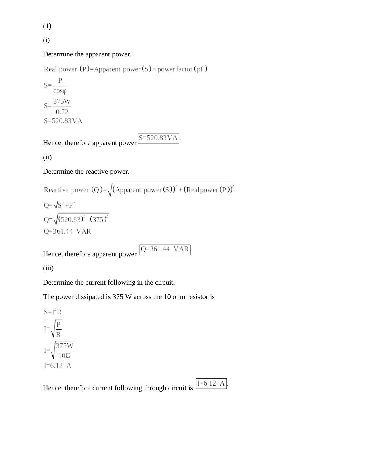
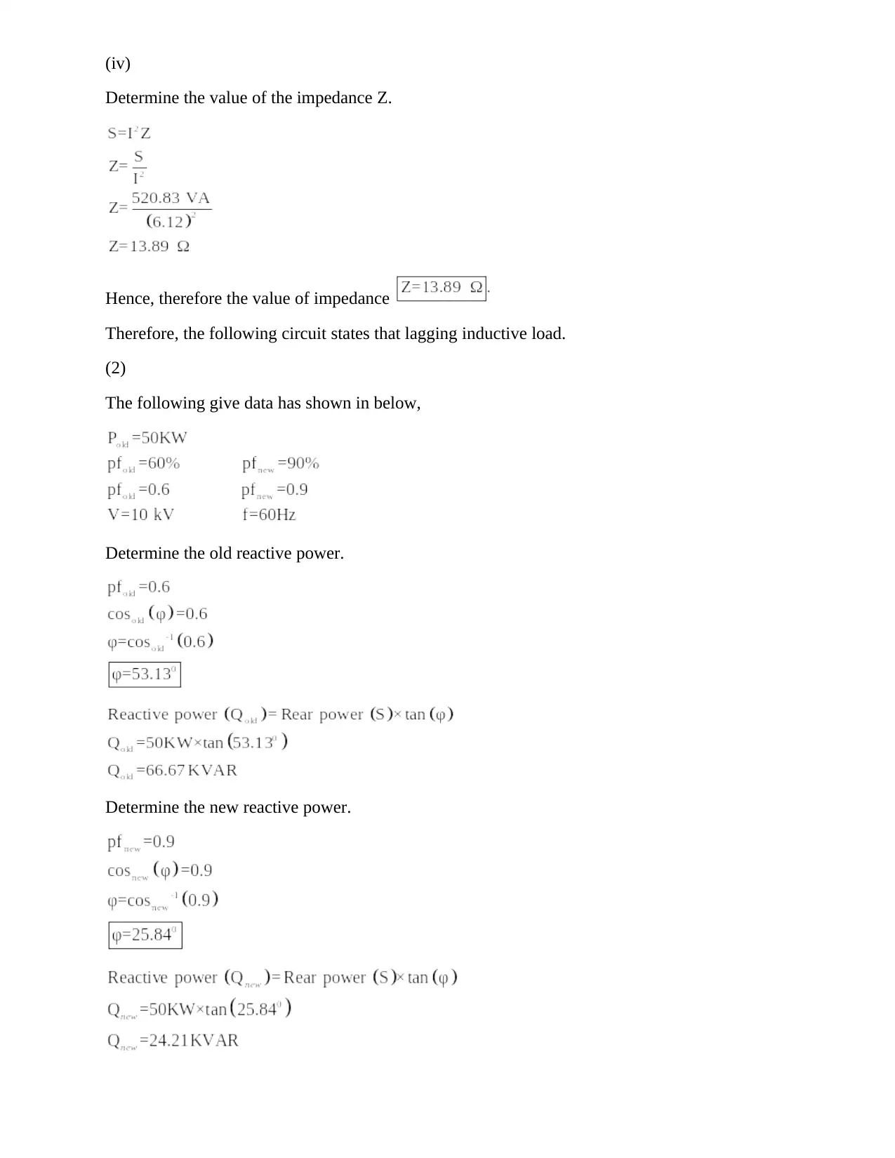
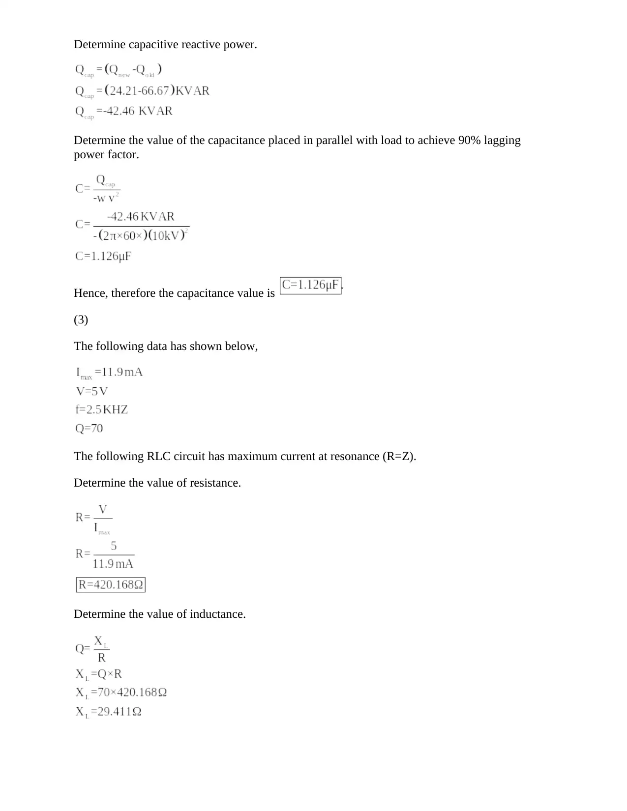
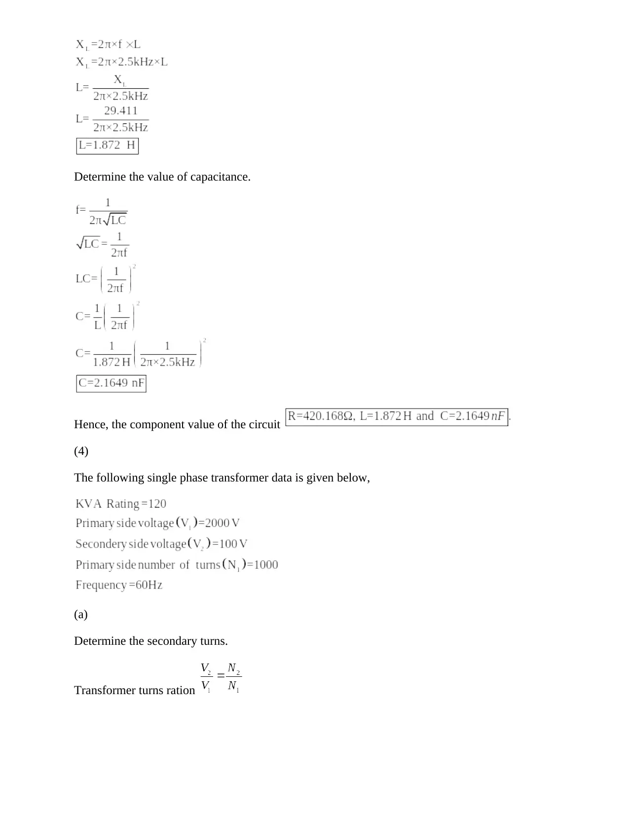
This document provides a comprehensive solution to an AC Circuits assignment. It covers several key areas including calculating apparent and reactive power, determining circuit currents and impedances, and analyzing the behavior of inductive loads. The assignment also includes problems related to transformers, such as determining turns ratios, primary and secondary currents, and maximum flux. Furthermore, the solution addresses voltage waveforms, harmonic analysis, and the calculation of voltage at specific time points, as well as the percentage error. The assignment is designed to test the understanding of fundamental AC circuit concepts and their application in practical scenarios, with a focus on problem-solving and analytical skills. This resource is valuable for electrical engineering students seeking to improve their understanding of AC circuits and excel in their coursework. This assignment is a part of the Teesside University, Engineering Science module.
Document Page
(1)
(i)
Determine the apparent power.
Hence, therefore apparent power
(ii)
Determine the reactive power.
Hence, therefore apparent power
(iii)
Determine the current following in the circuit.
The power dissipated is 375 W across the 10 ohm resistor is
Hence, therefore current following through circuit is
tabler-icon-diamond-filled.svg

Paraphrase This Document

Need a fresh take? Get an instant paraphrase of this document with our AI Paraphraser
Document Page
(iv)
Determine the value of the impedance Z.
Hence, therefore the value of impedance
Therefore, the following circuit states that lagging inductive load.
(2)
The following give data has shown in below,
Determine the old reactive power.
Determine the new reactive power.
Document Page
Determine capacitive reactive power.
Determine the value of the capacitance placed in parallel with load to achieve 90% lagging
power factor.
Hence, therefore the capacitance value is
(3)
The following data has shown below,
The following RLC circuit has maximum current at resonance (R=Z).
Determine the value of resistance.
Determine the value of inductance.
Document Page
Determine the value of capacitance.
Hence, the component value of the circuit
(4)
The following single phase transformer data is given below,
(a)
Determine the secondary turns.
Transformer turns ration
tabler-icon-diamond-filled.svg

Paraphrase This Document

Need a fresh take? Get an instant paraphrase of this document with our AI Paraphraser
Document Page
Hence, the secondary number of turns is
(b)
Determine the rated primary and secondary currents.
Calculate the primary current.
Calculate secondary current.
Hence, the transformer primary and secondary current are
(c)
Determine the maximum flux.
The single phase transformer has EMF equation is
Document Page
Hence, the maximum flux of the transformer is
(d)
Determine the cross-sectional area of the transformer core.
Hence, the area of cross section of transformer is
(5)
The following AC VOLTAGE data is given below,
(i)
Calculate for expression for voltage waveform.
Fundamental voltage
Fundamental frequency
The 3rd harmonic voltage is 20 % of fundamental voltage
The 3rd harmonic frequency is 3f.
Document Page
The 5th harmonic voltage is 10 % of fundamental voltage
The 5th harmonic frequency is 5f.
The following voltage wave form expression can write as
(ii)
The following wave form of the harmonics component has shown in figure 1-a.
(iii)
Determine the voltage at 20ms.
tabler-icon-diamond-filled.svg

Paraphrase This Document

Need a fresh take? Get an instant paraphrase of this document with our AI Paraphraser
Document Page
(iv)
Determine the percentage of error at 20ms.
The fundamental voltage
chevron_up_icon
1 out of 8
circle_padding
hide_on_mobile
zoom_out_icon
[object Object]