HNC Engineering: Two-Port Networks Assignment in Electrical Principles

Verified

Added on  2023/04/22

|9
|1188
|274
Homework Assignment
AI Summary
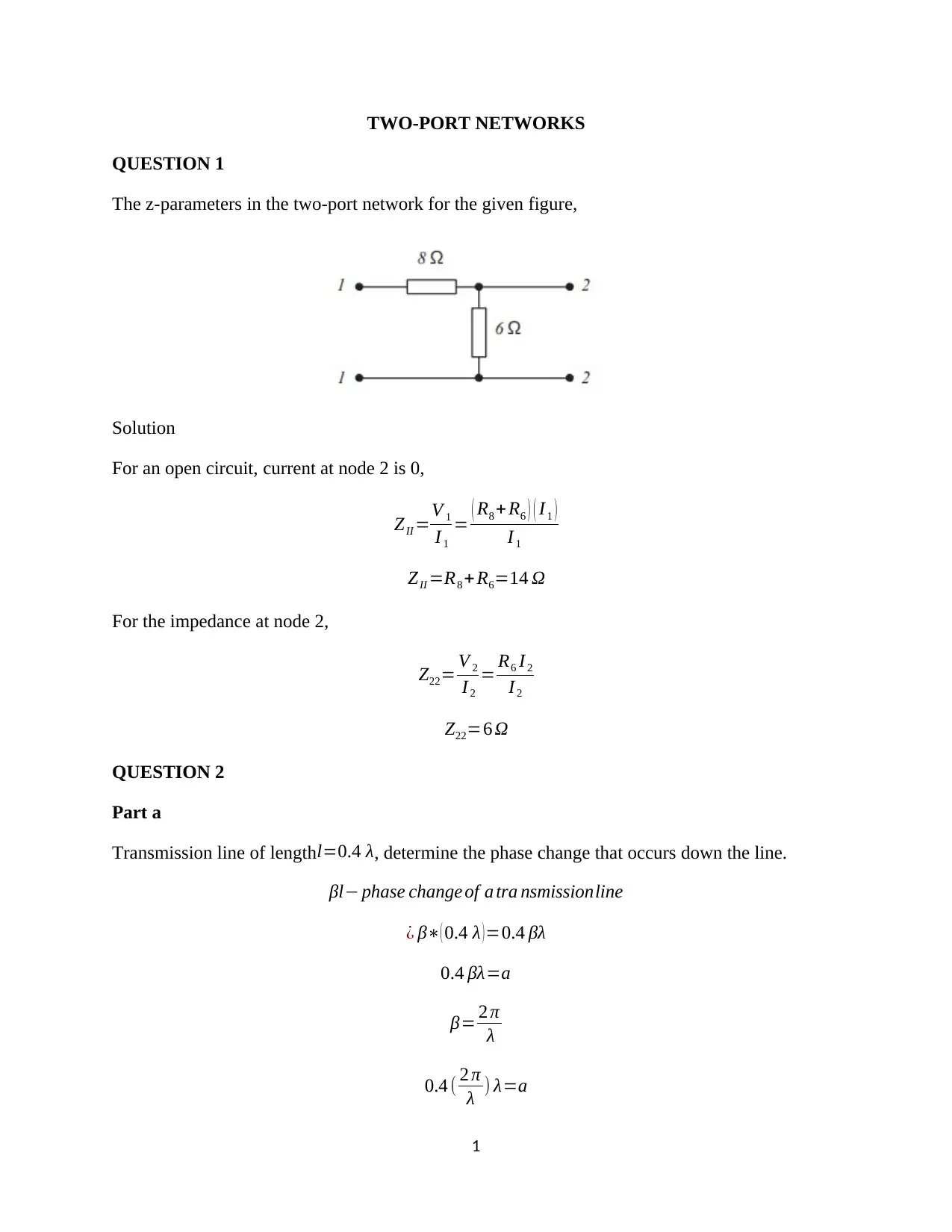
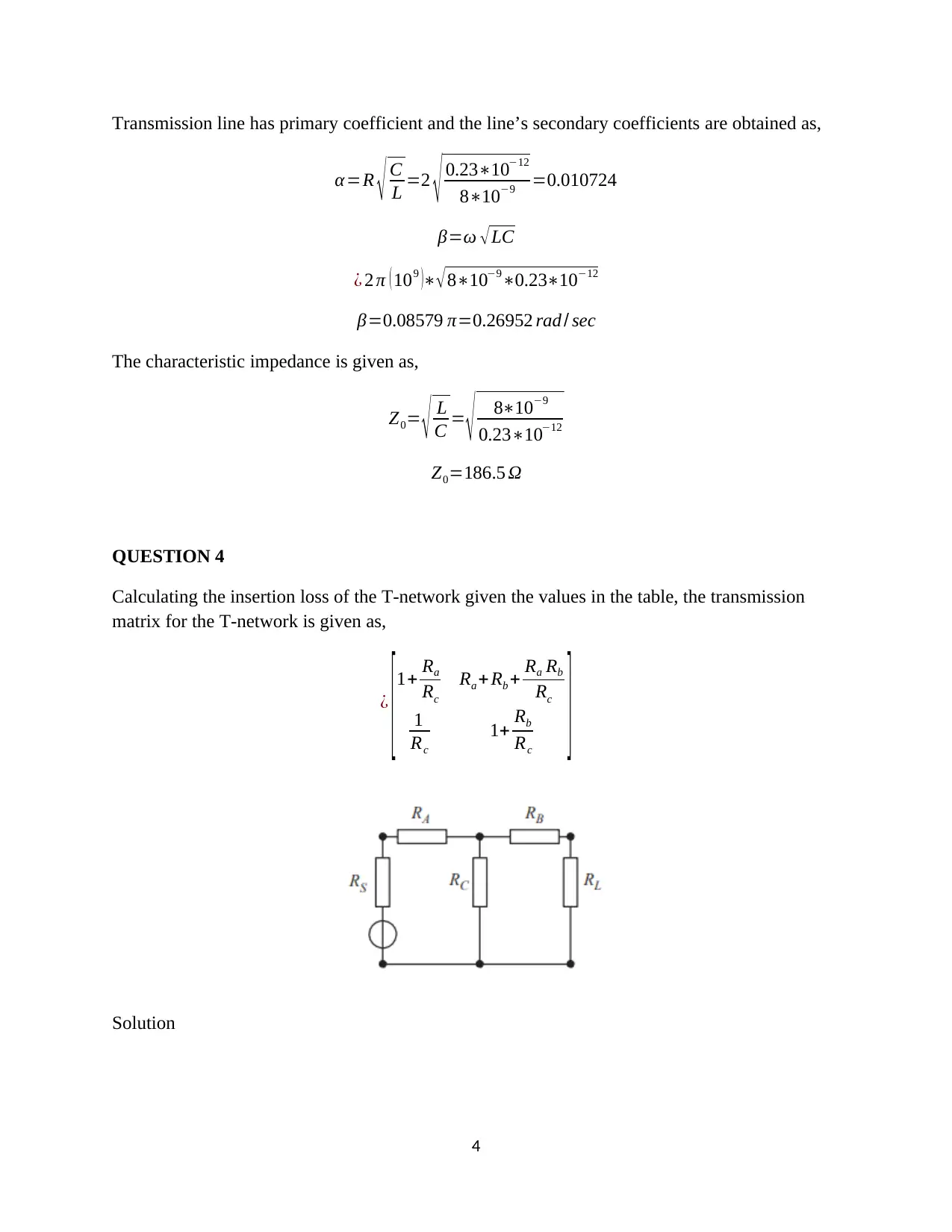
This document provides a comprehensive solution to an HNC Engineering assignment focusing on Two-Port Networks within the context of Electrical and Electronic Principles. The solution covers various aspects including calculating z-parameters for a given network, determining phase change and input impedance of a transmission line, analyzing distortionless and lossless transmission lines, calculating insertion loss of a T-network, and applying ABCD parameters to analyze high voltage transmission lines. Specific calculations and derivations are provided for each question, offering a detailed understanding of the underlying concepts and methodologies. Desklib offers a wide range of solved assignments and study tools for students.
Document Page
HNC Engineering Assignment
tabler-icon-diamond-filled.svg

Paraphrase This Document

Need a fresh take? Get an instant paraphrase of this document with our AI Paraphraser
Document Page
TWO-PORT NETWORKS
QUESTION 1
The z-parameters in the two-port network for the given figure,
Solution
For an open circuit, current at node 2 is 0,
ZII =V 1
I 1
= ( R8 +R6 ) ( I1 )
I 1
ZII =R8 + R6=14 Ω
For the impedance at node 2,
Z22= V 2
I 2
= R6 I 2
I 2
Z22=6 Ω
QUESTION 2
Part a
Transmission line of length l=0.4 λ, determine the phase change that occurs down the line.
βl phase change of a tra nsmissionline
¿ β( 0.4 λ )=0.4 βλ
0.4 βλ=a
β= 2 π
λ
0.4 ( 2 π
λ ) λ=a
1
Document Page
a=0.8 π=1440 phase change
Part b
Z¿=Z0
( ZL cos βl+ j Z0 sin βl )
Z0 cos βl+ jsin βl
Replacing the input impedance equation with values,
Z¿=(50 Ω) ( ( 40+ j30 ) Ωcos 0.4 βλ + j(50 Ω)sin 0.4 βλ )
( 50 Ω ) cos 0.4 βλ+ jsin 0.4 βλ
0.4 βλ=a
Z¿=(50 Ω) ( ( 40+ j 30 ) Ωcos a+ j (50 Ω)sin a )
( 50 Ω ) cos a+ jsin a
Z¿=50 ( 40 cos a+ j(30 cos a+50 sin a) )
50 cos a+ jsin a
Z¿=50 ( 40 cos 0.8 π + j ( 30 cos 0.8 π +50 sin 0.8 π ) )
50 cos 0.8 π + jsin 0.8 π
¿ 50 ( 40 cos 144+ j (30 cos 144+50 sin 144 ) )
50 cos 144 + jsin 144
Z¿=50 400.87115+ j ( 300.87115+50(0.49102 ) )
500.87115 j 0.49102
Z¿=50 34.846+ j1.5835
43.5575 j 0.49102
The input impedance is given as,
Z¿=39.97443+ j2.26834
QUESTION 3
Part a
A transmission line is said to be distortionless when there is no dispersion and the line
parameters are given in the ratio,
2
Document Page
R
L =G
C
The propagation constant can be expressed as,
γ= ( R+ jωL ) ( G+ jωC )
γ= LC ( R
L + )( G
C + )
It is further simplified as,
¿ ( R
L + ) LC
¿ R C
L + LC
α= { γ } =R C
L
β= { γ }=ω LC
A transmission line is said to be lossless when R=G=0. The transmission line’s characteristic
impedance of a lossless transmission line is purely real and the wave propagation constant is
purely imaginary. The lossless transmission line is given such that,
γ= ( R+ jωL ) ( G+ jωC )
R=G=0
γ= ( jωL ) ( jωC )
γ= ω2 LC
γ= LC
Hence,
α=0 , β=ω LC
Part b
3
tabler-icon-diamond-filled.svg

Paraphrase This Document

Need a fresh take? Get an instant paraphrase of this document with our AI Paraphraser
Document Page
Transmission line has primary coefficient and the line’s secondary coefficients are obtained as,
α=R C
L =2 0.231012
8109 =0.010724
β=ω LC
¿ 2 π ( 109 )81090.231012
β=0.08579 π=0.26952 rad / sec
The characteristic impedance is given as,
Z0= L
C = 8109
0.231012
Z0=186.5 Ω
QUESTION 4
Calculating the insertion loss of the T-network given the values in the table, the transmission
matrix for the T-network is given as,
¿
[1+ Ra
Rc
Ra + Rb + Ra Rb
Rc
1
Rc
1+ Rb
Rc
]
Solution
4
Document Page
¿
[1+ 13
213 13+13+ ( 13 ) ( 13 )
213
1
213 1+ 13
213 ]
¿ [ 1.061 26.7934
0.004695 1.061 ]
To obtain the insertion loss of the T-network,
AIL=20 log [ A RL+ B+ ( C RL+ D ) Rs
2
Rs +RL ]
The transmission matrix forms parts A, B, C, D. Therefore,
AIL=20 log [ (1.061100)+26.7934+ ( 0.004695100+1.061 ) ( 75 )2
75+100 ]
AIL=20 log ¿ ¿
AIL=20 log [ 49.0862 ]
AIL=33.82 dB
QUESTION 5
Part a
High voltage transmission line which illustrates the relationship between the sending and
receiving end voltages and currents using the complex ABCD equations,
V s =V r ( A1 + j A2 ) +Ir ( B1 + j B2)
I s=V r ( C1 + j C2 ) + Ir ( D1 + j D2 )
The s and r initials are for the sending end and receiving end.
5
Document Page
The sending end and receiving end equation are given as,
V s =V r ( A1 + j A2 ) +Ir ( B1 + j B2)
V s =V r ( 0.8698+ j 0.03542 ) +I r ( 47.94+ j180.8 )
For an open circuit, Ir=0,
V s =88.9 kV ( 0.8698+ j 0.03542 )
V s =77.325+ j 3.14884 kV
I s=V r ( C1 + j C2 ) + Ir ( D1 + j D2 )
I s=V r ( 0+ j 0.001349 ) + Ir ( 0.8698+ j 0.03542 )
I s=88.9 kV ( 0+ j 0.001349 )
I s= ( j119.9261 ) A
The short circuited power is obtained from the Vs and Is values,
PSO = { V s I s }
PSO = { ( 77.325+ j 3.14884 kV )( j119.9261 ) A }
PSO =0.377565 MWatts
Part b
6
tabler-icon-diamond-filled.svg

Paraphrase This Document

Need a fresh take? Get an instant paraphrase of this document with our AI Paraphraser
Document Page
The transmission line is 50km long T-circuit.
The shunt reactance is given as admittance, Y2 with Z1 and Z3 as the series impedances. The
following matrix is used in the solution,
[ A B
C D ]Z1 Y2 Z3
=
[1+ Z1 Y 2 Z1 Y 2 Z3
Y 2 1+Y 2 Z3 ]
Solving the different admittances and impedances,
Z1 =0.5 ( R + jωL )T Llength
Z1 =26.26+ j 96.52
f =50 Hz
Hence,
26.26+ j 96.52=0.5 ( R+ j(2 π (50))L )50
Solving further,
( 26.26+ j 96.52 )2
50 = ( R + j(2 π (50)) L )
( R+ j(100 π ) L )=1.05+ j3.86
Therefore, the values of R and L can be obtained as,
R=1.05 Ω per length
L= j 3.86
j 100 π =0.0122 H per length
For Y2,
7
Document Page
Y 2= ( G+ jωC )T Llength
G= 1
R = 1
1.05 =0.9524
0.001349
50 = ( 0.9524+ j ( 100 π ) C )
0.95237= j ( 100 π ) C
C=0.95237
j ( 100 π ) = j0. 02992 F=29.92 mF
8
chevron_up_icon
1 out of 9
circle_padding
hide_on_mobile
zoom_out_icon
[object Object]