Electrical Engineering: CPV, HVDC, and Power Factor Analysis
VerifiedAdded on 2021/05/17
|18
|3480
|361
Homework Assignment
AI Summary
This document presents a comprehensive solution to an electrical engineering assignment. The first part critically discusses concentrated photovoltaics (CPV) in comparison to conventional photovoltaic systems, delving into their operational principles, efficiency, and applications. The second part analyzes an industrial load scenario involving synchronous and induction motors, calculating annual cost savings based on power factor adjustments. The third part examines the causes and effects of distorted waveforms on the power factor, explaining harmonic distortion sources and their consequences on electrical systems. Finally, the document critically discusses the advantages of bipolar over monopole HVDC transmission systems, comparing their configurations and operational characteristics.
Question #1
a) Critically discuss concentration photovoltaics (CPV) in comparison to conventional
photovoltaics systems.
Answer:
Conventional PV
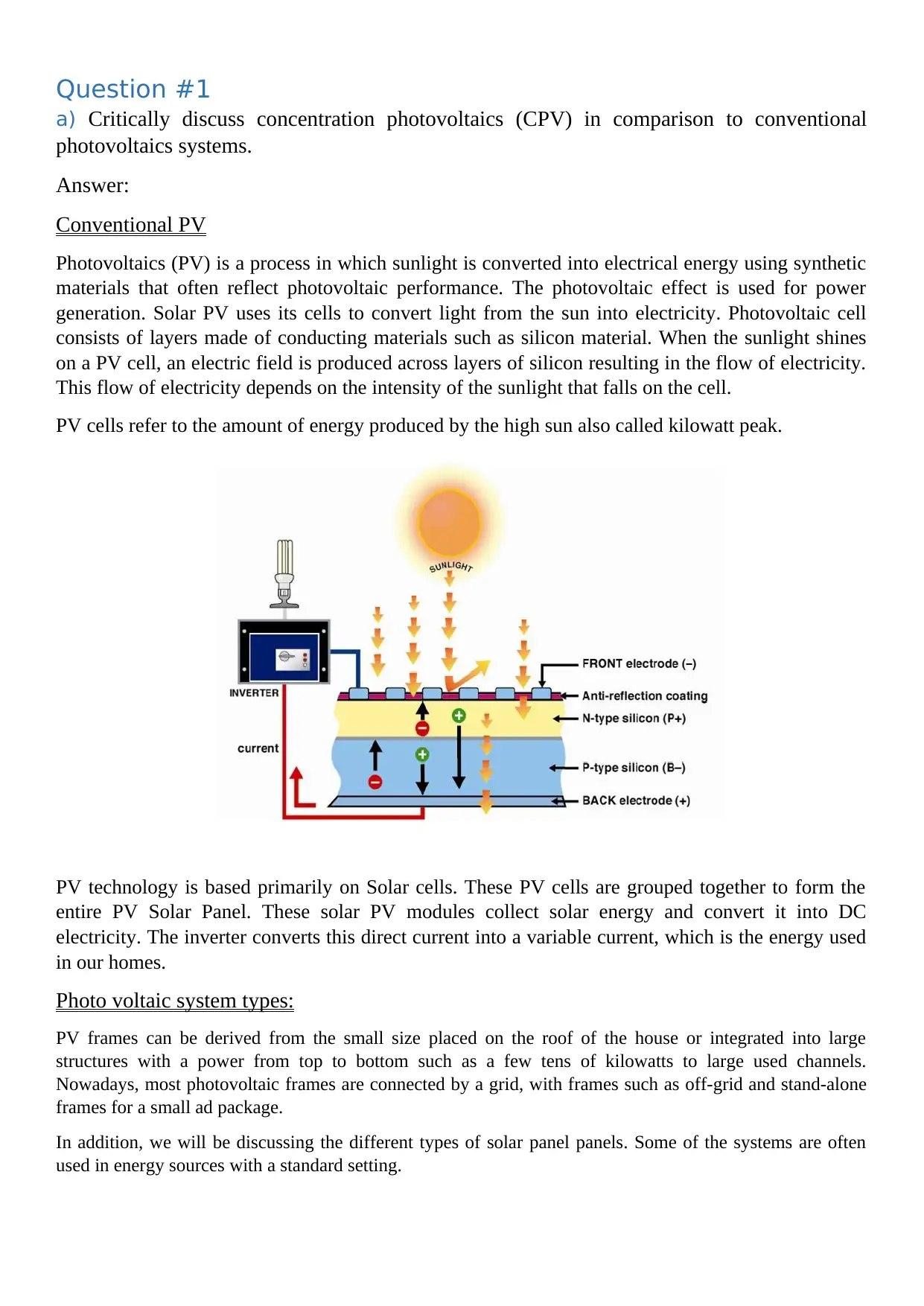
Photovoltaics (PV) is a process in which sunlight is converted into electrical energy using synthetic
materials that often reflect photovoltaic performance. The photovoltaic effect is used for power
generation. Solar PV uses its cells to convert light from the sun into electricity. Photovoltaic cell
consists of layers made of conducting materials such as silicon material. When the sunlight shines
on a PV cell, an electric field is produced across layers of silicon resulting in the flow of electricity.
This flow of electricity depends on the intensity of the sunlight that falls on the cell.
PV cells refer to the amount of energy produced by the high sun also called kilowatt peak.
PV technology is based primarily on Solar cells. These PV cells are grouped together to form the
entire PV Solar Panel. These solar PV modules collect solar energy and convert it into DC
electricity. The inverter converts this direct current into a variable current, which is the energy used
in our homes.
Photo voltaic system types:
PV frames can be derived from the small size placed on the roof of the house or integrated into large
structures with a power from top to bottom such as a few tens of kilowatts to large used channels.
Nowadays, most photovoltaic frames are connected by a grid, with frames such as off-grid and stand-alone
frames for a small ad package.
In addition, we will be discussing the different types of solar panel panels. Some of the systems are often
used in energy sources with a standard setting.
a) Critically discuss concentration photovoltaics (CPV) in comparison to conventional
photovoltaics systems.
Answer:
Conventional PV
Photovoltaics (PV) is a process in which sunlight is converted into electrical energy using synthetic
materials that often reflect photovoltaic performance. The photovoltaic effect is used for power
generation. Solar PV uses its cells to convert light from the sun into electricity. Photovoltaic cell
consists of layers made of conducting materials such as silicon material. When the sunlight shines
on a PV cell, an electric field is produced across layers of silicon resulting in the flow of electricity.
This flow of electricity depends on the intensity of the sunlight that falls on the cell.
PV cells refer to the amount of energy produced by the high sun also called kilowatt peak.
PV technology is based primarily on Solar cells. These PV cells are grouped together to form the
entire PV Solar Panel. These solar PV modules collect solar energy and convert it into DC
electricity. The inverter converts this direct current into a variable current, which is the energy used
in our homes.
Photo voltaic system types:
PV frames can be derived from the small size placed on the roof of the house or integrated into large
structures with a power from top to bottom such as a few tens of kilowatts to large used channels.
Nowadays, most photovoltaic frames are connected by a grid, with frames such as off-grid and stand-alone
frames for a small ad package.
In addition, we will be discussing the different types of solar panel panels. Some of the systems are often
used in energy sources with a standard setting.
Paraphrase This Document
Need a fresh take? Get an instant paraphrase of this document with our AI Paraphraser
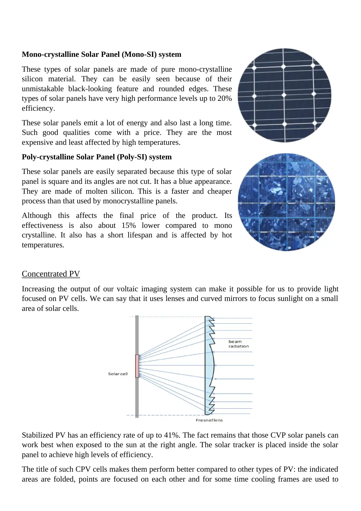
Mono-crystalline Solar Panel (Mono-SI) system
These types of solar panels are made of pure mono-crystalline
silicon material. They can be easily seen because of their
unmistakable black-looking feature and rounded edges. These
types of solar panels have very high performance levels up to 20%
efficiency.
These solar panels emit a lot of energy and also last a long time.
Such good qualities come with a price. They are the most
expensive and least affected by high temperatures.
Poly-crystalline Solar Panel (Poly-SI) system
These solar panels are easily separated because this type of solar
panel is square and its angles are not cut. It has a blue appearance.
They are made of molten silicon. This is a faster and cheaper
process than that used by monocrystalline panels.
Although this affects the final price of the product. Its
effectiveness is also about 15% lower compared to mono
crystalline. It also has a short lifespan and is affected by hot
temperatures.
Concentrated PV
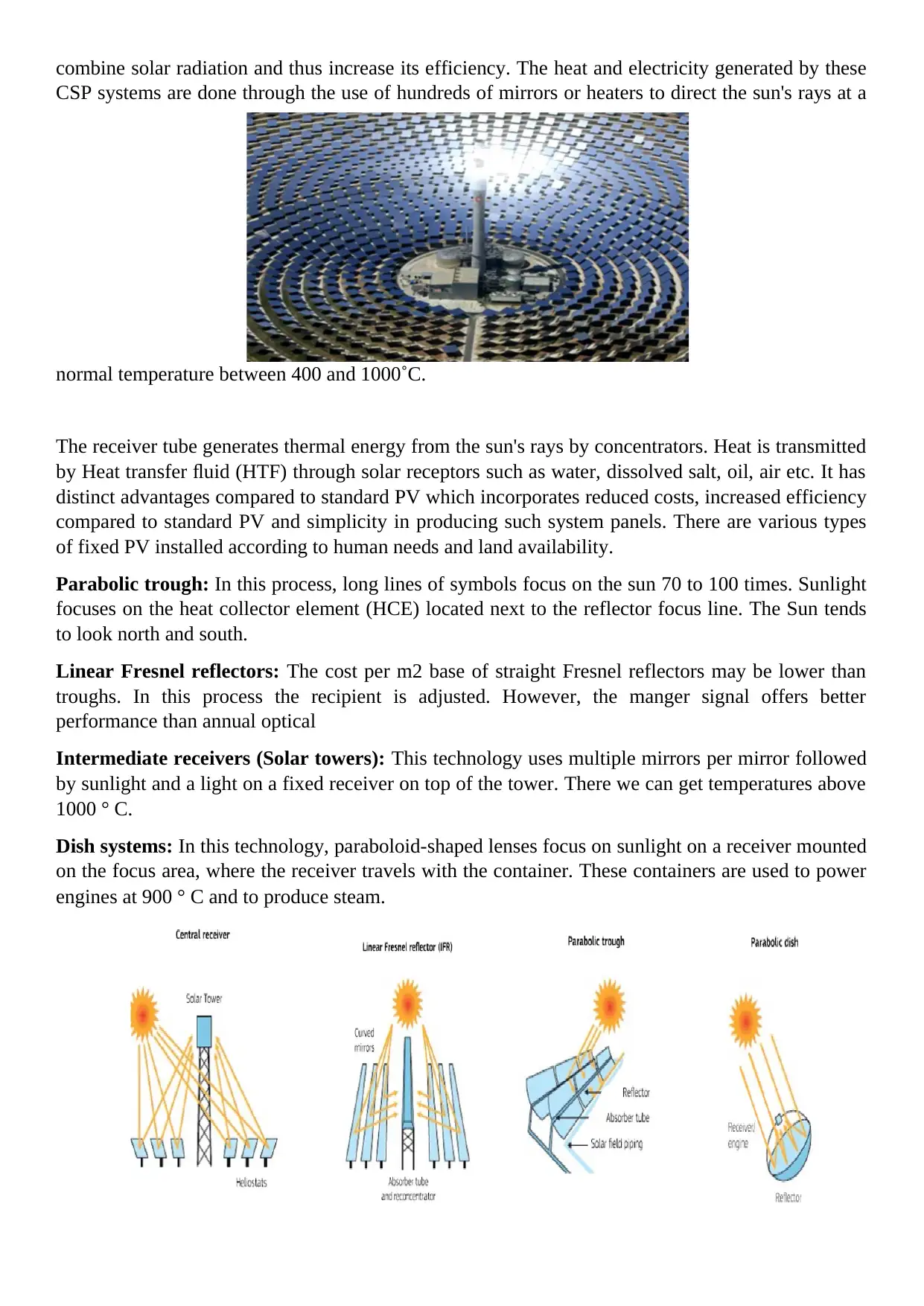
Increasing the output of our voltaic imaging system can make it possible for us to provide light
focused on PV cells. We can say that it uses lenses and curved mirrors to focus sunlight on a small
area of solar cells.
Stabilized PV has an efficiency rate of up to 41%. The fact remains that those CVP solar panels can
work best when exposed to the sun at the right angle. The solar tracker is placed inside the solar
panel to achieve high levels of efficiency.
The title of such CPV cells makes them perform better compared to other types of PV: the indicated
areas are folded, points are focused on each other and for some time cooling frames are used to
These types of solar panels are made of pure mono-crystalline
silicon material. They can be easily seen because of their
unmistakable black-looking feature and rounded edges. These
types of solar panels have very high performance levels up to 20%
efficiency.
These solar panels emit a lot of energy and also last a long time.
Such good qualities come with a price. They are the most
expensive and least affected by high temperatures.
Poly-crystalline Solar Panel (Poly-SI) system
These solar panels are easily separated because this type of solar
panel is square and its angles are not cut. It has a blue appearance.
They are made of molten silicon. This is a faster and cheaper
process than that used by monocrystalline panels.
Although this affects the final price of the product. Its
effectiveness is also about 15% lower compared to mono
crystalline. It also has a short lifespan and is affected by hot
temperatures.
Concentrated PV
Increasing the output of our voltaic imaging system can make it possible for us to provide light
focused on PV cells. We can say that it uses lenses and curved mirrors to focus sunlight on a small
area of solar cells.
Stabilized PV has an efficiency rate of up to 41%. The fact remains that those CVP solar panels can
work best when exposed to the sun at the right angle. The solar tracker is placed inside the solar
panel to achieve high levels of efficiency.
The title of such CPV cells makes them perform better compared to other types of PV: the indicated
areas are folded, points are focused on each other and for some time cooling frames are used to
combine solar radiation and thus increase its efficiency. The heat and electricity generated by these
CSP systems are done through the use of hundreds of mirrors or heaters to direct the sun's rays at a
normal temperature between 400 and 1000˚C.
The receiver tube generates thermal energy from the sun's rays by concentrators. Heat is transmitted
by Heat transfer fluid (HTF) through solar receptors such as water, dissolved salt, oil, air etc. It has
distinct advantages compared to standard PV which incorporates reduced costs, increased efficiency
compared to standard PV and simplicity in producing such system panels. There are various types
of fixed PV installed according to human needs and land availability.
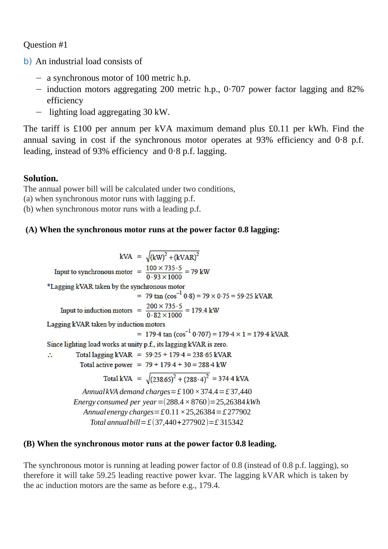
Parabolic trough: In this process, long lines of symbols focus on the sun 70 to 100 times. Sunlight
focuses on the heat collector element (HCE) located next to the reflector focus line. The Sun tends
to look north and south.
Linear Fresnel reflectors: The cost per m2 base of straight Fresnel reflectors may be lower than
troughs. In this process the recipient is adjusted. However, the manger signal offers better
performance than annual optical
Intermediate receivers (Solar towers): This technology uses multiple mirrors per mirror followed
by sunlight and a light on a fixed receiver on top of the tower. There we can get temperatures above
1000 ° C.
Dish systems: In this technology, paraboloid-shaped lenses focus on sunlight on a receiver mounted
on the focus area, where the receiver travels with the container. These containers are used to power
engines at 900 ° C and to produce steam.
CSP systems are done through the use of hundreds of mirrors or heaters to direct the sun's rays at a
normal temperature between 400 and 1000˚C.
The receiver tube generates thermal energy from the sun's rays by concentrators. Heat is transmitted
by Heat transfer fluid (HTF) through solar receptors such as water, dissolved salt, oil, air etc. It has
distinct advantages compared to standard PV which incorporates reduced costs, increased efficiency
compared to standard PV and simplicity in producing such system panels. There are various types
of fixed PV installed according to human needs and land availability.
Parabolic trough: In this process, long lines of symbols focus on the sun 70 to 100 times. Sunlight
focuses on the heat collector element (HCE) located next to the reflector focus line. The Sun tends
to look north and south.
Linear Fresnel reflectors: The cost per m2 base of straight Fresnel reflectors may be lower than
troughs. In this process the recipient is adjusted. However, the manger signal offers better
performance than annual optical
Intermediate receivers (Solar towers): This technology uses multiple mirrors per mirror followed
by sunlight and a light on a fixed receiver on top of the tower. There we can get temperatures above
1000 ° C.
Dish systems: In this technology, paraboloid-shaped lenses focus on sunlight on a receiver mounted
on the focus area, where the receiver travels with the container. These containers are used to power
engines at 900 ° C and to produce steam.
⊘ This is a preview!⊘
Do you want full access?
Subscribe today to unlock all pages.
Trusted by 1+ million students worldwide
Question #1
b) An industrial load consists of
a synchronous motor of 100 metric h.p.
induction motors aggregating 200 metric h.p., 0·707 power factor lagging and 82%
efficiency
lighting load aggregating 30 kW.
The tariff is £100 per annum per kVA maximum demand plus £0.11 per kWh. Find the
annual saving in cost if the synchronous motor operates at 93% efficiency and 0·8 p.f.
leading, instead of 93% efficiency and 0·8 p.f. lagging.
Solution.
The annual power bill will be calculated under two conditions,
(a) when synchronous motor runs with lagging p.f.
(b) when synchronous motor runs with a leading p.f.
(A) When the synchronous motor runs at the power factor 0.8 lagging:
Annual kVA demand charges=£ 100 ×374.4=£ 37,440
Energy consumed per year =(288.4 × 8760)=25,26384 kWh
Annual energy charges=£ 0.11 ×25,26384=£ 277902
Total annualbill=£ (37,440+277902)=£ 315342
(B) When the synchronous motor runs at the power factor 0.8 leading.
The synchronous motor is running at leading power factor of 0.8 (instead of 0.8 p.f. lagging), so
therefore it will take 59.25 leading reactive power kvar. The lagging kVAR which is taken by
the ac induction motors are the same as before e.g., 179.4.
Paraphrase This Document
Need a fresh take? Get an instant paraphrase of this document with our AI Paraphraser

Annual kVA demand charges=£ 100 ×312.4=£ 31,240
Annual energy charges=£ 2,77,902
Total annualbill=£ (31,240+277902)=£ 3,09,142
Annual saving=£ (315342−3,09,142)=£ 6200
Question #1
c) Discuss causes and effects of distorted waveforms on Power Factor (P.F).
Answer:
Definition of Harmonic Distortion
Harmonic distortion is formed by such a load obtained by the current measurement at each
stage of the harmonic frequency.
Causes of harmonics
Harmonic is actually created because of the indirect loads that include switching a large
network will produce harmonics and the load-related filter form is analyzed and divided into
components to produce harmonic spectrum. The following are just a few examples of
electronic devices that produce harmonics:
UPS, Motors, fans and pumps
Servers having the leading p.f.
PCs, video monitors, digital printers and photocopiers
Lights, Fluorescent lights and low voltage lights
VSDs, VFDs and power supplies (switched-mode)
Rectifiers, power converters and Thyristor controls
Chillers, compressors, coolers, freezers and microwave cookers
Equipment for heating and ventilation
Effects of harmonics
The high level of current distortion is the reason for the Voltage separation and the level of
THDU depends largely on the source block. Therefore, the higher the source of impedance
will create a higher THDU value.
Below are a few of the things that happen as a result of system distortion:
1) Mains voltage distortion
⊘ This is a preview!⊘
Do you want full access?
Subscribe today to unlock all pages.
Trusted by 1+ million students worldwide
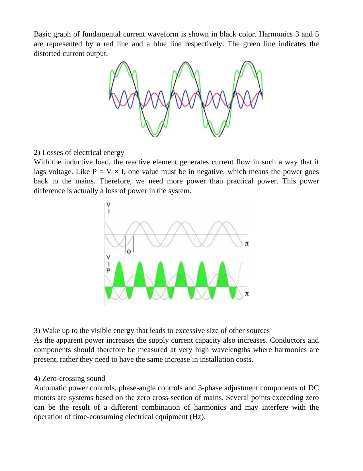
Basic graph of fundamental current waveform is shown in black color. Harmonics 3 and 5
are represented by a red line and a blue line respectively. The green line indicates the
distorted current output.
2) Losses of electrical energy
With the inductive load, the reactive element generates current flow in such a way that it
lags voltage. Like P = V × I, one value must be in negative, which means the power goes
back to the mains. Therefore, we need more power than practical power. This power
difference is actually a loss of power in the system.
3) Wake up to the visible energy that leads to excessive size of other sources
As the apparent power increases the supply current capacity also increases. Conductors and
components should therefore be measured at very high wavelengths where harmonics are
present, rather they need to have the same increase in installation costs.
4) Zero-crossing sound
Automatic power controls, phase-angle controls and 3-phase adjustment components of DC
motors are systems based on the zero cross-section of mains. Several points exceeding zero
can be the result of a different combination of harmonics and may interfere with the
operation of time-consuming electrical equipment (Hz).
Paraphrase This Document
Need a fresh take? Get an instant paraphrase of this document with our AI Paraphraser
5) Failure of stand-by generating sets
Harmonics can cause a lot of problems if you switch from large transmission lines to stand
by power such as in hospitals.
6) Transformers overheating
Due to the presence of harmonic currents, transformer windings often suffer increased
copper losses. Also due to skin effect, at high frequencies the resistance can increase
hugely. The conductors in transformer can suffer from harmonic built up which can result in
the increase of phase current by a 2.1 factor.
7) Negative rotation sequences in motors
In an imported vehicle, the external stator has existing coils supplied by AC in order to
produce the rotating magnetic force which is accompanied by the Rotor. Few harmonics
produce high losses on the car that can cause excessive heat to the car and lead to temporary
failure.
8) Damage to capacitors
A large power system network is considered a power input in inductive form. Its impedance
increases with frequency. In general, the impedance of capacitors decreases with frequency.
At high frequencies, harmonic currents may flow to the capacitors.
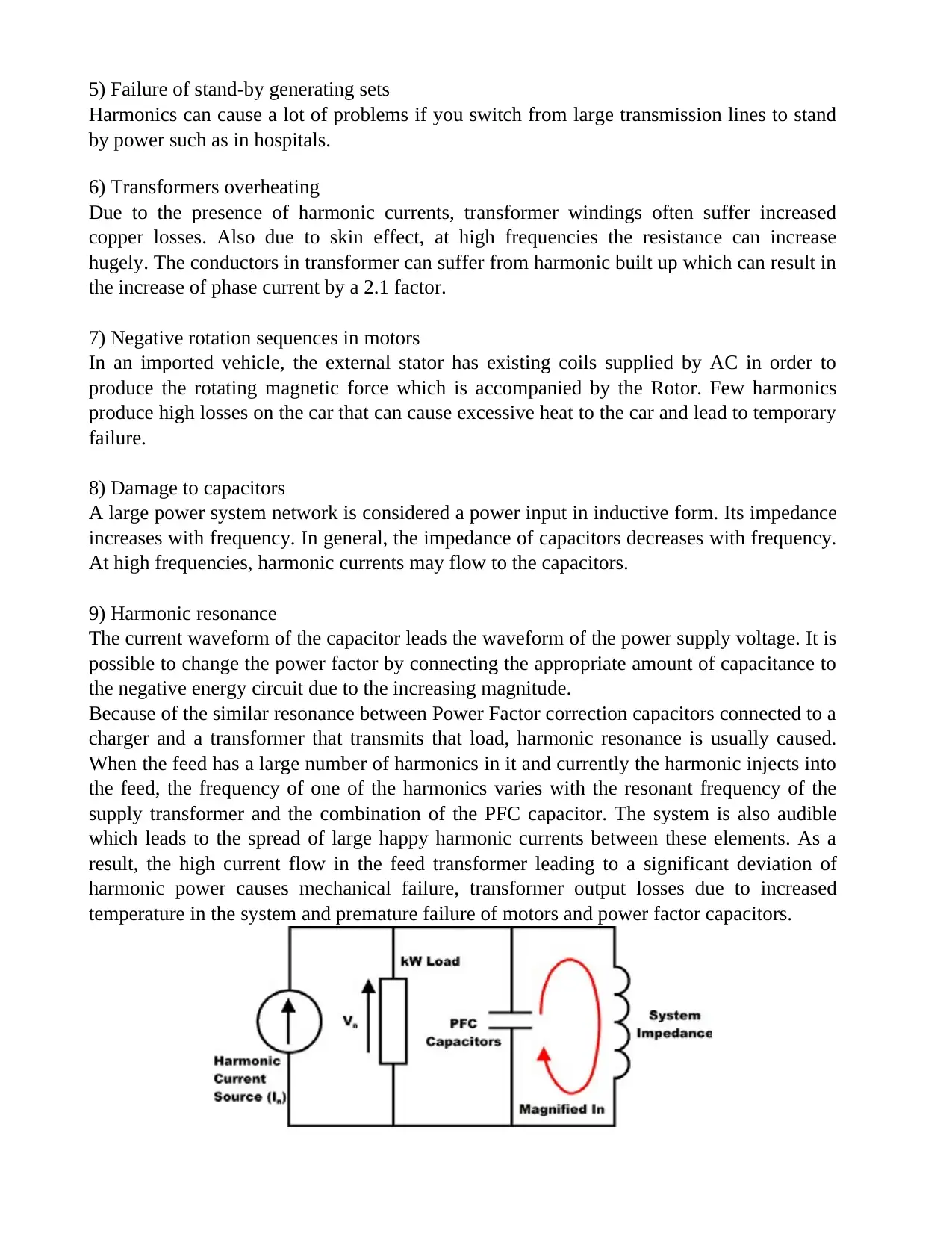
9) Harmonic resonance
The current waveform of the capacitor leads the waveform of the power supply voltage. It is
possible to change the power factor by connecting the appropriate amount of capacitance to
the negative energy circuit due to the increasing magnitude.
Because of the similar resonance between Power Factor correction capacitors connected to a
charger and a transformer that transmits that load, harmonic resonance is usually caused.
When the feed has a large number of harmonics in it and currently the harmonic injects into
the feed, the frequency of one of the harmonics varies with the resonant frequency of the
supply transformer and the combination of the PFC capacitor. The system is also audible
which leads to the spread of large happy harmonic currents between these elements. As a
result, the high current flow in the feed transformer leading to a significant deviation of
harmonic power causes mechanical failure, transformer output losses due to increased
temperature in the system and premature failure of motors and power factor capacitors.
Harmonics can cause a lot of problems if you switch from large transmission lines to stand
by power such as in hospitals.
6) Transformers overheating
Due to the presence of harmonic currents, transformer windings often suffer increased
copper losses. Also due to skin effect, at high frequencies the resistance can increase
hugely. The conductors in transformer can suffer from harmonic built up which can result in
the increase of phase current by a 2.1 factor.
7) Negative rotation sequences in motors
In an imported vehicle, the external stator has existing coils supplied by AC in order to
produce the rotating magnetic force which is accompanied by the Rotor. Few harmonics
produce high losses on the car that can cause excessive heat to the car and lead to temporary
failure.
8) Damage to capacitors
A large power system network is considered a power input in inductive form. Its impedance
increases with frequency. In general, the impedance of capacitors decreases with frequency.
At high frequencies, harmonic currents may flow to the capacitors.
9) Harmonic resonance
The current waveform of the capacitor leads the waveform of the power supply voltage. It is
possible to change the power factor by connecting the appropriate amount of capacitance to
the negative energy circuit due to the increasing magnitude.
Because of the similar resonance between Power Factor correction capacitors connected to a
charger and a transformer that transmits that load, harmonic resonance is usually caused.
When the feed has a large number of harmonics in it and currently the harmonic injects into
the feed, the frequency of one of the harmonics varies with the resonant frequency of the
supply transformer and the combination of the PFC capacitor. The system is also audible
which leads to the spread of large happy harmonic currents between these elements. As a
result, the high current flow in the feed transformer leading to a significant deviation of
harmonic power causes mechanical failure, transformer output losses due to increased
temperature in the system and premature failure of motors and power factor capacitors.
Question: 02
a)
Critically discuss the advantages of bipolar over monopole HVDC transmission
systems.
Answer:
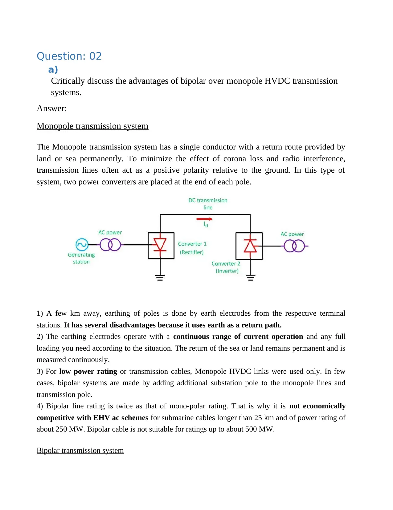
Monopole transmission system
The Monopole transmission system has a single conductor with a return route provided by
land or sea permanently. To minimize the effect of corona loss and radio interference,
transmission lines often act as a positive polarity relative to the ground. In this type of
system, two power converters are placed at the end of each pole.
1) A few km away, earthing of poles is done by earth electrodes from the respective terminal
stations. It has several disadvantages because it uses earth as a return path.
2) The earthing electrodes operate with a continuous range of current operation and any full
loading you need according to the situation. The return of the sea or land remains permanent and is
measured continuously.
3) For low power rating or transmission cables, Monopole HVDC links were used only. In few
cases, bipolar systems are made by adding additional substation pole to the monopole lines and
transmission pole.
4) Bipolar line rating is twice as that of mono-polar rating. That is why it is not economically
competitive with EHV ac schemes for submarine cables longer than 25 km and of power rating of
about 250 MW. Bipolar cable is not suitable for ratings up to about 500 MW.
Bipolar transmission system
a)
Critically discuss the advantages of bipolar over monopole HVDC transmission
systems.
Answer:
Monopole transmission system
The Monopole transmission system has a single conductor with a return route provided by
land or sea permanently. To minimize the effect of corona loss and radio interference,
transmission lines often act as a positive polarity relative to the ground. In this type of
system, two power converters are placed at the end of each pole.
1) A few km away, earthing of poles is done by earth electrodes from the respective terminal
stations. It has several disadvantages because it uses earth as a return path.
2) The earthing electrodes operate with a continuous range of current operation and any full
loading you need according to the situation. The return of the sea or land remains permanent and is
measured continuously.
3) For low power rating or transmission cables, Monopole HVDC links were used only. In few
cases, bipolar systems are made by adding additional substation pole to the monopole lines and
transmission pole.
4) Bipolar line rating is twice as that of mono-polar rating. That is why it is not economically
competitive with EHV ac schemes for submarine cables longer than 25 km and of power rating of
about 250 MW. Bipolar cable is not suitable for ratings up to about 500 MW.
Bipolar transmission system
⊘ This is a preview!⊘
Do you want full access?
Subscribe today to unlock all pages.
Trusted by 1+ million students worldwide
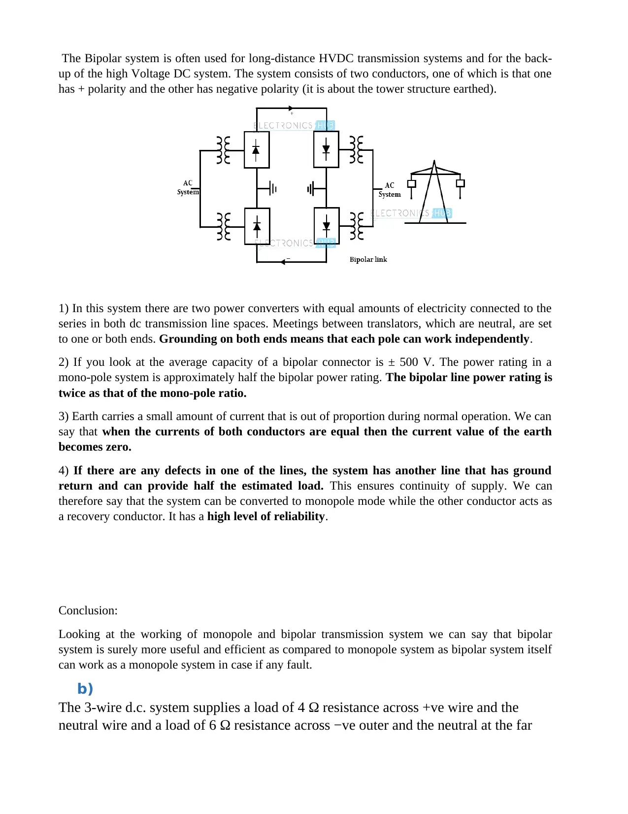
The Bipolar system is often used for long-distance HVDC transmission systems and for the back-
up of the high Voltage DC system. The system consists of two conductors, one of which is that one
has + polarity and the other has negative polarity (it is about the tower structure earthed).
1) In this system there are two power converters with equal amounts of electricity connected to the
series in both dc transmission line spaces. Meetings between translators, which are neutral, are set
to one or both ends. Grounding on both ends means that each pole can work independently.
2) If you look at the average capacity of a bipolar connector is ± 500 V. The power rating in a
mono-pole system is approximately half the bipolar power rating. The bipolar line power rating is
twice as that of the mono-pole ratio.
3) Earth carries a small amount of current that is out of proportion during normal operation. We can
say that when the currents of both conductors are equal then the current value of the earth
becomes zero.
4) If there are any defects in one of the lines, the system has another line that has ground
return and can provide half the estimated load. This ensures continuity of supply. We can
therefore say that the system can be converted to monopole mode while the other conductor acts as
a recovery conductor. It has a high level of reliability.
Conclusion:
Looking at the working of monopole and bipolar transmission system we can say that bipolar
system is surely more useful and efficient as compared to monopole system as bipolar system itself
can work as a monopole system in case if any fault.
b)
The 3-wire d.c. system supplies a load of 4 Ω resistance across +ve wire and the
neutral wire and a load of 6 Ω resistance across −ve outer and the neutral at the far
Paraphrase This Document
Need a fresh take? Get an instant paraphrase of this document with our AI Paraphraser
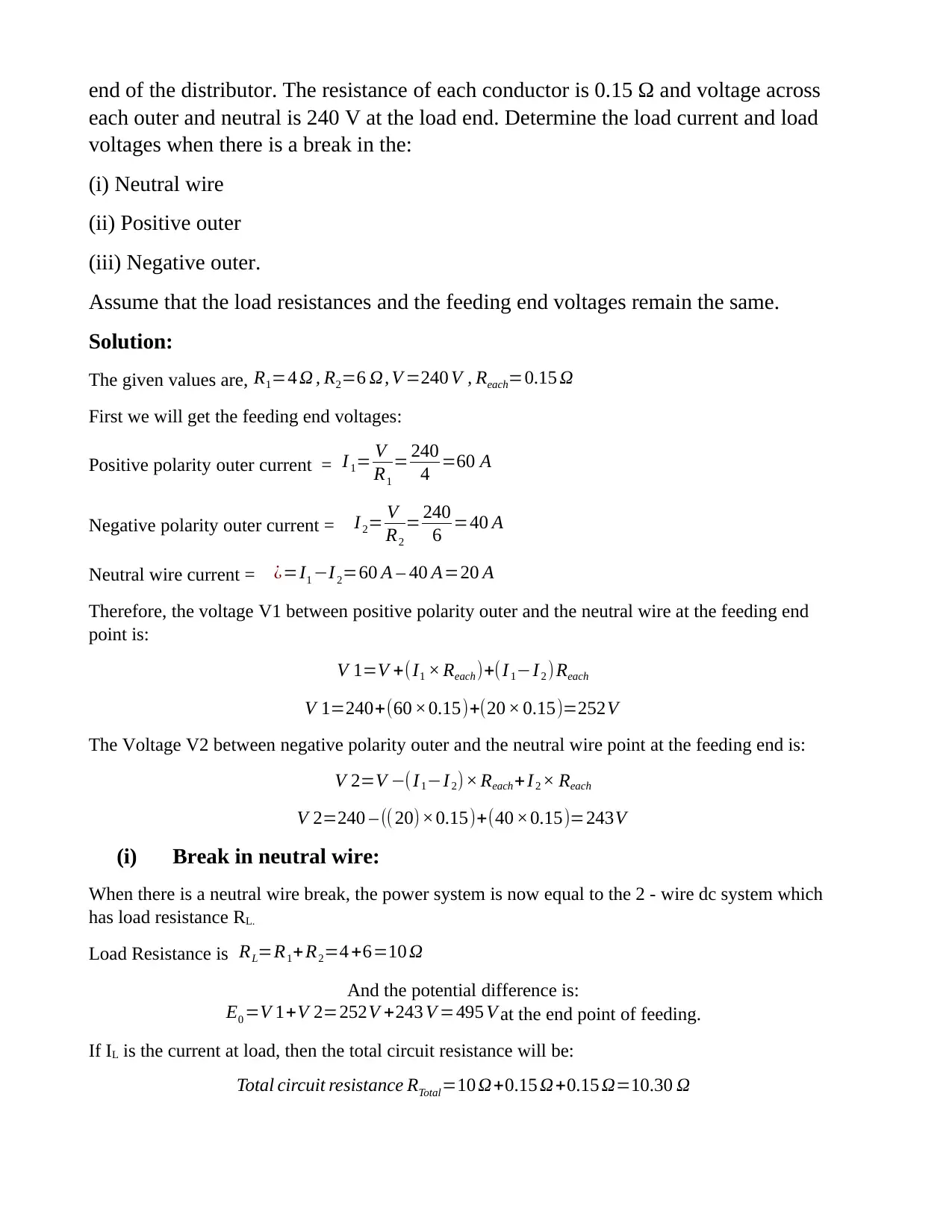
end of the distributor. The resistance of each conductor is 0.15 Ω and voltage across
each outer and neutral is 240 V at the load end. Determine the load current and load
voltages when there is a break in the:
(i) Neutral wire
(ii) Positive outer
(iii) Negative outer.
Assume that the load resistances and the feeding end voltages remain the same.
Solution:
The given values are, R1=4 Ω , R2=6 Ω, V =240 V , Reach=0.15 Ω
First we will get the feeding end voltages:
Positive polarity outer current = I 1= V
R1
= 240
4 =60 A
Negative polarity outer current = I 2= V
R2
= 240
6 =40 A
Neutral wire current = ¿=I1 −I 2=60 A – 40 A=20 A
Therefore, the voltage V1 between positive polarity outer and the neutral wire at the feeding end
point is:
V 1=V +(I1 × Reach)+(I 1−I 2 )Reach
V 1=240+(60 ×0.15)+(20 × 0.15)=252V
The Voltage V2 between negative polarity outer and the neutral wire point at the feeding end is:
V 2=V −( I1−I2)× Reach+ I2 × Reach
V 2=240 – (( 20)×0.15)+(40 ×0.15)=243V
(i) Break in neutral wire:
When there is a neutral wire break, the power system is now equal to the 2 - wire dc system which
has load resistance RL.
Load Resistance is RL=R1+ R2=4 +6=10 Ω
And the potential difference is:
E0 =V 1+V 2=252V +243 V =495 V at the end point of feeding.
If IL is the current at load, then the total circuit resistance will be:
Total circuit resistance RTotal=10 Ω+0.15 Ω+0.15 Ω=10.30 Ω
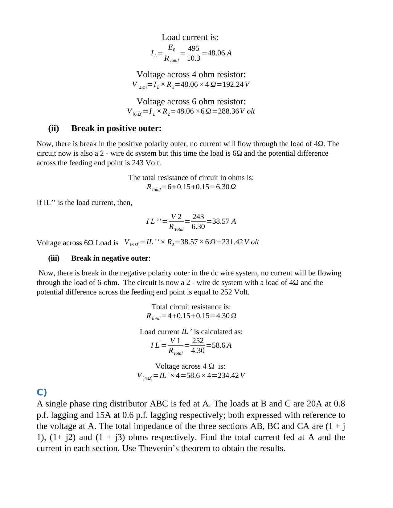
Load current is:
I L= E0
RTotal
= 495
10.3 =48.06 A
Voltage across 4 ohm resistor:
V ( 4 Ω ) =I L × R1=48.06 × 4 Ω=192.24 V
Voltage across 6 ohm resistor:
V (6 Ω)=I L × R2=48.06 ×6 Ω=288.36V olt
(ii) Break in positive outer:
Now, there is break in the positive polarity outer, no current will flow through the load of 4Ω. The
circuit now is also a 2 - wire dc system but this time the load is 6Ω and the potential difference
across the feeding end point is 243 Volt.
The total resistance of circuit in ohms is:
RTotal=6+ 0.15+0.15=6.30 Ω
If IL’’ is the load current, then,
I L ’'= V 2
RTotal
= 243
6.30 =38.57 A
Voltage across 6Ω Load is V (6 Ω)=IL ’ ' × R2=38.57 × 6 Ω=231.42 V olt
(iii) Break in negative outer:
Now, there is break in the negative polarity outer in the dc wire system, no current will be flowing
through the load of 6-ohm. The circuit is now a 2 - wire dc system with a load of 4Ω and the
potential difference across the feeding end point is equal to 252 Volt.
Total circuit resistance is:
RTotal=4+0.15+0.15=4.30 Ω
Load current IL ’ is calculated as:
I L'= V 1
RTotal
= 252
4.30 =58.6 A
Voltage across 4 Ω is:
V (4 Ω)=IL' × 4=58.6 × 4=234.42 V
C)
A single phase ring distributor ABC is fed at A. The loads at B and C are 20A at 0.8
p.f. lagging and 15A at 0.6 p.f. lagging respectively; both expressed with reference to
the voltage at A. The total impedance of the three sections AB, BC and CA are (1 + j
1), (1+ j2) and (1 + j3) ohms respectively. Find the total current fed at A and the
current in each section. Use Thevenin’s theorem to obtain the results.
⊘ This is a preview!⊘
Do you want full access?
Subscribe today to unlock all pages.
Trusted by 1+ million students worldwide
1 out of 18
Related Documents


Your All-in-One AI-Powered Toolkit for Academic Success.
+13062052269
info@desklib.com
Available 24*7 on WhatsApp / Email
![[object Object]](/_next/static/media/star-bottom.7253800d.svg)
Unlock your academic potential
Copyright © 2020–2026 A2Z Services. All Rights Reserved. Developed and managed by ZUCOL.