Project Report: Three Phase Fault Analysis and Auto Reset System

Verified

Added on  2020/04/21

|8
|1640
|266
Report
AI Summary
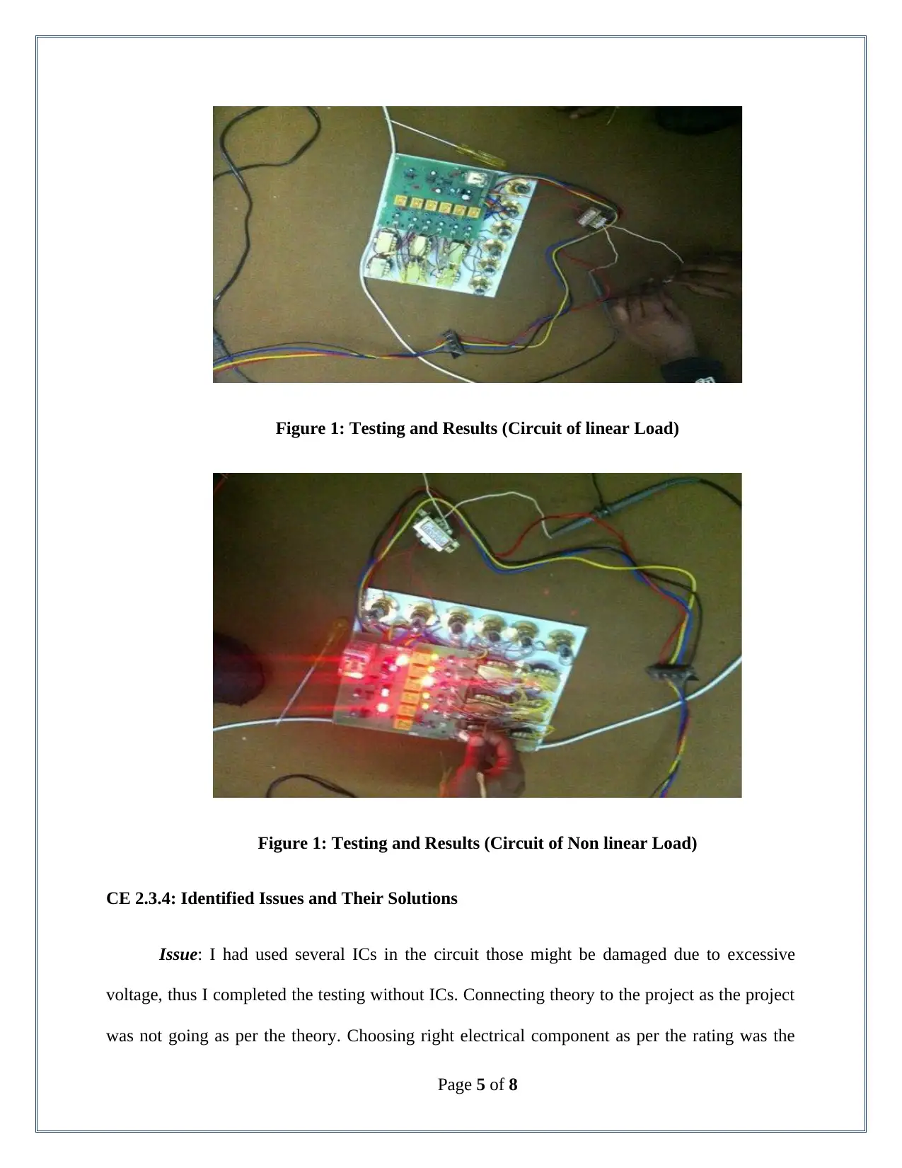
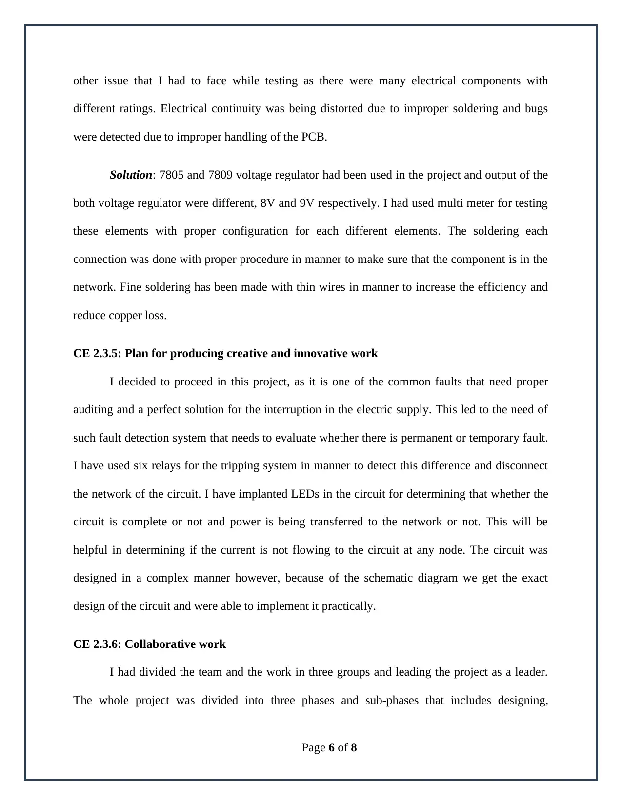
This report details a student's project on a three-phase fault analysis system with an auto-reset mechanism for temporary faults and a trip function for permanent faults. The project aimed to design and implement a system capable of detecting various fault types (3L, LL, LG) in a three-phase supply. The student, acting as team leader, designed the circuit, conducted hardware testing, and ensured proper component selection. The system utilized transformers, relays, and timers to differentiate between temporary and permanent faults, automatically resetting for the former and tripping for the latter. The report outlines the project's objectives, the student's responsibilities, the engineering knowledge applied, issues encountered (such as potential IC damage), and the solutions implemented. Collaborative efforts, circuit design, and testing results are thoroughly discussed, providing a comprehensive overview of the project's development and successful implementation.
Document Page
tabler-icon-diamond-filled.svg

Paraphrase This Document

Need a fresh take? Get an instant paraphrase of this document with our AI Paraphraser
Document Page
CE 2.1: Project Introduction
Name of the Project : Three Phase Fault Analysis with Auto Reset for Temporary Fault
and Trip for Permanent Fault
Geographical Location : [Please Fill]
Project Duration : [Please Fill]
Organization : [Please Fill]
Position in the Project : Team Leader
CE 2.2: Project Background
CE 2.2.1: Characteristics of the Project
There have been many studies made regarding the faults in the overhead lines those show
that 70% to 90% of the faults on these lines are transient. Insulator flashover is a transient fault
that is cleared by immediate tripping of one or more circuit breakers in manner to isolate the
identified fault. The electrical substations those supply electricity to the population of the sector
might suffer certain failures due to certain faults no matter it is small or big. These faults include
3L (three lines), LL (Line to Line), and LG (Line to Ground) in the supply systems and this
could affect the power system of that area. This project is a successful attempt to make a system
that can be helpful in sensing such faults. Based on this detection, automatic tripping mechanism
has been introduced to the project that will work according to the type of the fault and will
respond accordingly.
Page 1 of 8
Document Page
CE 2.2.2: Objectives developed for project
Successful designing of this project needs proper electrical engineering knowledge in
manner to create an effective system to detect such faults and prevent from further destruction.
The objective of this report can be listed as:
To develop a tripping mechanism for three phase supply system;
To detect major or minor faults in the power supply;
To disconnect the connection between the customers and power stations;
To present a star input and star output network for three connected transformers;
CE 2.2.3: My area of work
I had designed the circuit and done hardware testing that includes two phases,
conductivity test and Power on test. I had to check whether the circuit was closed and the
continuity of the power supply. I had used multi meter and a bundle of wires in manner to
evaluate whether all the elements of the circuit are receiving the rated voltage and current or not.
I had performed the power on test without ICs and using multi meter in the voltage mode. I
checked whether the output voltage of the transformer is 12V AC or not (and batteries are fully
charged or not).
CE 2.2.4: Project Group
Page 2 of 8
Document Page
Figure 2: Team Member Associated for the completion of the project
CE 2.2.5: My responsibilities throughout the project
I was responsible for the complete circuit of the project and made sure that the circuit was
closed and power was supplying to every element. I chose the proper rated components in
manner to make sure that the power is supplied or divided among them. I chose the medium
price devices (neither most cheaply not costly) for making sure that the recorded readings are
specific and original even up to four digits after the decimal. I took the responsibility for the
evaluation of each element and used marking system for them.
CE 2.3: Distinctive Activity
CE 2.3.1: Comprehending the Theory of the project
After a brief interruption in the power supply, the project automatically resets for the case
of temporary faults and for permanent faults the project remains in the tripped condition. This
system can sense the faults including major, minor, temporary, and permanent faults in the 3L,
Page 3 of 8
tabler-icon-diamond-filled.svg

Paraphrase This Document

Need a fresh take? Get an instant paraphrase of this document with our AI Paraphraser
Document Page
LG, and LL supply systems. I have designed the whole setup in a manner that the connection
will be tripped whenever there is a fault detected in the electric supply. I have used three single-
phase transformers and connected them in star connection and three other transformers in delta
connection and the rated voltage for the transformers are 220V input and 20V output. In
addition, I have added the 555 timers for handling the long and short duration faults.
CE 2.3.2: Engineering Knowledge and Skills applied in the project
I had used six numbers step-down transformers to operate the whole circuit at low
voltage and maintain the voltage flow at 12V for testing the three-phase fault analysis. Primary
winding of the transformer was connected in star to the three phase and the secondary windings
were connected in delta configuration. Outputs of the transformers were filtered and rectified to
the individually and were given to the six relay coils. I have designed the circuit and relays in
manner that if the nature of the fault is temporary or pushed button is released immediately. Op-
Amp output through a positive feedback remains high indefinitely for its pin 1 to pin 3 through a
resistor and forward biased connected in series. This setup will be helpful in detecting the faults
in the three-phase supply system that could affect the power system.
CE 2.3.3: Accomplishment and Task Performed
The project was a successful system after testing, in the form of three single-phase
transformers 230V to 12V for the development of an automatic tripping mechanism. Testing was
initiated after the soldering process however; soldering was made two times, as ICs were needed
to be removed before testing. This could be helpful in determining the permanent and temporary
faults in the supply of the electricity. Temporary trip will detect the short duration fault and
permanent trip will be helpful in detecting the long duration faults.
Page 4 of 8
Document Page
Figure 1: Testing and Results (Circuit of linear Load)
Figure 1: Testing and Results (Circuit of Non linear Load)
CE 2.3.4: Identified Issues and Their Solutions
Issue: I had used several ICs in the circuit those might be damaged due to excessive
voltage, thus I completed the testing without ICs. Connecting theory to the project as the project
was not going as per the theory. Choosing right electrical component as per the rating was the
Page 5 of 8
Document Page
other issue that I had to face while testing as there were many electrical components with
different ratings. Electrical continuity was being distorted due to improper soldering and bugs
were detected due to improper handling of the PCB.
Solution: 7805 and 7809 voltage regulator had been used in the project and output of the
both voltage regulator were different, 8V and 9V respectively. I had used multi meter for testing
these elements with proper configuration for each different elements. The soldering each
connection was done with proper procedure in manner to make sure that the component is in the
network. Fine soldering has been made with thin wires in manner to increase the efficiency and
reduce copper loss.
CE 2.3.5: Plan for producing creative and innovative work
I decided to proceed in this project, as it is one of the common faults that need proper
auditing and a perfect solution for the interruption in the electric supply. This led to the need of
such fault detection system that needs to evaluate whether there is permanent or temporary fault.
I have used six relays for the tripping system in manner to detect this difference and disconnect
the network of the circuit. I have implanted LEDs in the circuit for determining that whether the
circuit is complete or not and power is being transferred to the network or not. This will be
helpful in determining if the current is not flowing to the circuit at any node. The circuit was
designed in a complex manner however, because of the schematic diagram we get the exact
design of the circuit and were able to implement it practically.
CE 2.3.6: Collaborative work
I had divided the team and the work in three groups and leading the project as a leader.
The whole project was divided into three phases and sub-phases that includes designing,
Page 6 of 8
tabler-icon-diamond-filled.svg

Paraphrase This Document

Need a fresh take? Get an instant paraphrase of this document with our AI Paraphraser
Document Page
implementing, and testing. One of my teammate designed the circuit and I have contributed in
the innovative thought of implementing six relays. Other member of my team made the circuit
that includes soldering wire and electrical components in the circuit. Each member of the team
was devoted to the project and left not any stone unturned to eliminate human errors. The third
phase was my responsibility alone that includes testing of the continuity and power on testing
and it was a time taking process.
CE 2.4: Project Review
CE 2.4.1: Project Overview
The project was designed using three single-phase transformers, six relays and many
other electrical components for rectifying the voltage and ICs have implanted in the circuit. This
project will help in detecting the faults and disconnecting the network of power supply as per the
case of the fault. Admittance method is used in the project to determine the fault current:
At 230V = 4A
At 12V = 8A
CE 2.4.2: My contribution to work
I worked as the team leader in the project, contributed to the designing of the circuit, and
tested the components after connection is made and connected to the circuit board. I made the
testing using multi meter, removing the ICs as the testing was being made using high voltage and
the ICs and transistors might fall in break down case.
Page 7 of 8
chevron_up_icon
1 out of 8
circle_padding
hide_on_mobile
zoom_out_icon
[object Object]