Design of Flyback Converter: Project Report and Analysis

Verified

Added on  2019/10/31

|9
|1658
|193
Report
AI Summary
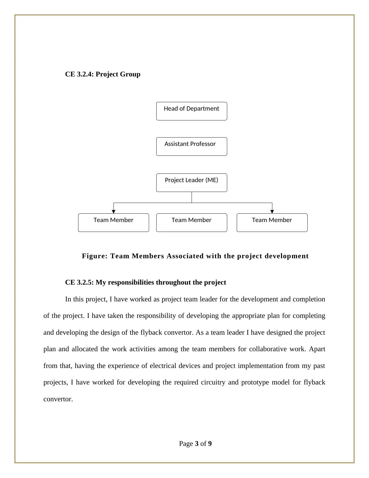
This report details a student's project on the design and implementation of a flyback converter. The project focuses on understanding the working principles, designing the topology, and implementing the converter for a 50W, 5V power supply. The report covers the project background, objectives, and the student's role as team leader. It describes the design process, including the selection of components like UCC3809 and error amplifiers, and the application of engineering knowledge to calculate duty cycles and transformer turns ratios. The student addressed technical issues, such as identical traces in continuous and discontinuous modes, by reviewing the experimental setup. The report highlights innovative aspects such as the implementation of an error amplifier on the secondary side and the use of voltage clamps to suppress voltage overshoot, leading to an improved design. The collaborative work and decision-making process are also discussed. The project aimed for a cost-effective, efficient design and incorporated measures to enhance performance compared to similar projects.
Document Page
Competency
Demonstration Report
(CDR)
Career Episode 3
tabler-icon-diamond-filled.svg

Paraphrase This Document

Need a fresh take? Get an instant paraphrase of this document with our AI Paraphraser
Document Page
CE 3.1: Project Introduction
Name of the Project : Design of Flyback Converter, Transformer Design
Geographical Location : [Please Fill]
Project Duration : [Please Fill]
Organization : [Please Fill]
Position in the Project : Team Leader
CE 3.2. Project Background
CE 3.2.1: Characteristics of the Project
In various multiple and single output dc to dc converters, the Flyback power sources
plays a significant role in at lower power levels at 150 watts or less. I have learnt that the flyback
converters used the inductor for storage of energy. Further, in telecommunication industry the
flyback converters are utilized for interfacing with various voltage ranges. In various topologies
derived on the buck convertor, are implemented with the use of push-pull or forward convertor
for reducing the significant amount of cost and component count. Therefore, in this project I
have worked for the understanding and evaluation of the working principle of the flyback
convertor. In addition to that, I have focused on designing and implementation of a flyback
convertor for this project. In this project I have used Precision Reference UC3965 along with
“Low Offset Error Amplifier” for driving the octocoupler used in this project.
Page 1 of 9
Document Page
CE 3.2.2: Objectives developed for project
In this project, I have developed my significant aim for the design of the flyback
converter. Prior to that; I have focused on understanding of the working principle for the flyback
converter. In addition to that, I was associated with the hardware implementation and circuit
design for the flyback converter for this project. In order to complete the project within allocated
deadline while ensuring all the possible deliverables I have developed the following objectives:
To identify the working principle for flyback converter;
To evaluate the system requirement and electrical equipments for the flyback
converter;
To determine the specifications for the power supply for the flyback converter;
To develop the topology design and control method for flyback converter;
To develop the appropriate design for the flyback transformer;
To provide the appropriate design and set up for the UCC3809 and error amplifier;
CE 3.2.3: My area of work
Before started working in the hardware implementation of the flyback converter, I have
determined the specification for the power supply for the flyback convertor. In this project, I
have ensured the 0A to 10 A of load, + 5V of DC output voltage, –72VDC to –32VDC input
voltage range and the 1500VRMS Isolation. In addition to that, I have developed the appropriate
design for the power stage of the flyback convertor and setting up with the required UCC3809.
In addition to that, I have also developed the preliminary circuit diagram for the error amplifier
in the secondary line.
Page 2 of 9
Document Page
Head of Department
Assistant Professor
Project Leader (ME)
Team MemberTeam Member Team Member
CE 3.2.4: Project Group
Figure: Team Members Associated with the project development
CE 3.2.5: My responsibilities throughout the project
In this project, I have worked as project team leader for the development and completion
of the project. I have taken the responsibility of developing the appropriate plan for completing
and developing the design of the flyback convertor. As a team leader I have designed the project
plan and allocated the work activities among the team members for collaborative work. Apart
from that, having the experience of electrical devices and project implementation from my past
projects, I have worked for developing the required circuitry and prototype model for flyback
convertor.
Page 3 of 9
tabler-icon-diamond-filled.svg

Paraphrase This Document

Need a fresh take? Get an instant paraphrase of this document with our AI Paraphraser
Document Page
CE 3.3: Distinctive Activity
CE 3.3.1: Comprehending the Theory of the project
For the design and implementation of the flyback convertor, I have learned that there
exists various types of topologies for the design. In this project I have considered the output,
input ripple currents, cost, isolation, simplicity and low power factor during the configuration of
the flyback convertor. I have further studies various articles and journals for evaluating the
working principle and identifying the configuration of the flyback converter. Based on the details
and information obtained from secondary sources I have developed a primary configuration
circuit for the converter as illustrated in the section below:
Figure: Preliminary Circuit Diagram for the flyback converter
In this project through the design and implementation of the 50 watt, 5 V power supply, I
have focused on achieving low cost yet efficient design of the flyback convertor. I have used
Page 4 of 9
Document Page
UCC3809 on the primary side for obtaining the current mode fixed frequency and on the
secondary side I have used precision reference and error amplifier.
CE 3.3.2: Engineering Knowledge and Skills applied in the project
I decided to use the topology for the control method for the finding of the maximum duty
cycle Dmaxshould be used. I found the duty cycle in the ratio of on time of Q1 to the total time D
= ton/T. later on with the help of this I found that the DC transferring function of a CCM flyback
converter in use to be:
From the above equation VO is equal to the output voltage of 5V, VD is the forwarded
voltage drop in the rectifier D1, VIN is the equal to 32V, VRds (ON) is the voltage drop across the
MOSFET Q1 which has been assumed to be 1V, N is the turn’s ratio of the transformer used
(Ns/Np), Ns is the secondary turns of the transformer, Np is the primary turns of the transformer
and D is the Duty cycle.
I found out that the maximum duty cycle can be of 0.45 which occurs at the point of
minimum input of voltage. I found that the turn’s ratio has been found to be inversely
proportional to the peak primary current.
CE 3.3.3: Accomplishment and Task Performed
Page 5 of 9
Document Page
I have studied various articles, journals and books for determining the appropriate
working principle of the flyback converter. After determining and understanding the working
principle and operation used in the flyback converter.
CE 3.3.4: Identified Issues and Their Solutions
Issue: After the development of the flyback convertor design and prototype model, I have
worked for examining the performance of the system. For this purpose I have used oscilloscope
traces for indicating the appropriate ground of the flyback convertor on both the primary and
secondary mode. I have faced significant technical issue in the project when the traces in the
continuous and discontinuous mode were found to be same.
Solution: For resolving the issue, I have checked and reviewed the experiment
environment and test rests. From the evaluation I have found that during the continuous mode of
the flyback convertor, the 1v gate was turned on those results in the similar output. I have further
switched off the 1V pin and observed the output to the different and satisfactory.
CE 3.3.5: Plan for producing creative and innovative work
In order to develop innovative and creative design in the flyback convertor, I have
implemented the error amplifier on the secondary side of the flyback convertor. I have further
developed the required design of the flyback convertor using the input-output isolation. In this
project, I have observed the UC3965 threshold of 4.1v. Further, for preventing the tripping of the
voltage ripple, I have implemented a decoupling capacitor of 47μF. Apart from that, for
controlling the on time FET discharging, I have used the Schottky diode in series formation.
Page 6 of 9
tabler-icon-diamond-filled.svg

Paraphrase This Document

Need a fresh take? Get an instant paraphrase of this document with our AI Paraphraser
Document Page
Through this, I was able to obtain the effective design and minimizing the error in the flyback
convertor.
CE 3.3.6: Collaborative work
Being a team leader, I have worked in this project for obtaining standard process and
effective design for the implementation of the flyback convertor. I have followed and developed
a communication matrix and resource allocation matrix for ensuring the proper flow of
information and availability of resources among the team members. In addition to that I have
provided the team members with efficient guidance and information for developing and
implementing the required design of flyback convertor.
CE 3.4: Project Review
CE 3.4.1: Decision Making Process
In this project I have worked as a team leader but worked for the implementation of the
flyback convertor. Therefore, I took the required decision and developed the appropriate plan for
the implementation of the flyback convertor. In this project, I have evaluated the project details
and divided the work into two major module. In the first module, I have worked for the
identification and evaluation of the operational and performances of the flyback convertor. In the
second phase, I have distributed the work among the project team for the implementation and
design of the required flyback convertor.
CE 3.4.2: Comparatively Better In This Project Among Other Similar Projects
In this project, I have used clams and snubbers in the flyback convertor for making the
project comparatively better than other available flyback convertor present in the market. I have
Page 7 of 9
Document Page
observed that the leakage in the transformer poses significant risks among the switching devices.
For overcoming this purpose I have used voltage clams for suppressing thee overshoot of voltage
of flyback convertor. Through this I was able to limit the peak switch voltage and significantly
reduce the power dissipation.
Page 8 of 9
chevron_up_icon
1 out of 9
circle_padding
hide_on_mobile
zoom_out_icon
[object Object]