Electrical Installation Design: Workshop Analysis and Calculations
VerifiedAdded on 2023/03/20
|10
|1651
|53
Homework Assignment
AI Summary
This assignment solution provides a comprehensive analysis of an electrical installation design for a workshop environment. It covers various aspects, starting with the sources of information, including the IET Wiring Regulations and other relevant guides. The solution details the wiring system for luminaires, specifying cable types, cross-sectional areas, and shielding considerations. It then addresses the power supply, including voltage, circuit type (radial), and protective devices like cut-out fuses. The assignment further examines the suspension of luminaires, earthing fault protection requirements (RCDs), and the design current calculation for an air compressor. The solution extends to circuit design for both three-phase and single-phase circuits, including calculations for design current, overcurrent protection, and CPC (Circuit Protective Conductor) sizing using the adiabatic formula. The document also covers notices, labeling, diagrams for luminaires, IP requirements for outdoor luminaires, and protective bonding. Furthermore, it explains prospective fault current, breaking capacity ratings (ICN, ICS), and coordination and discrimination of protective devices. Finally, it emphasizes the importance of inspection and testing for electrical installations and the recommended intervals.
QUESTION ONE
Sources of information
1. IET Wiring Regulation (17th Edition BS 7671_2008)
2. ON-SITE GUIDE BS 7671 17th Edition BS 7671 2008
3. Electrical Installation Design Guide, calculation for
electricians and designers 4th edition
4. Electricians Guide to the building regulation by Paul Cook
5. Guide to wiring regulations by Darrell Locke
QUESTION TWO
Luminaires wiring system for the main workshop
Type of cables-single core sheathed cables in a conduit
mounted on a wall-conduit used as there are more than one
circuits and a single core used to pave way for easier circuit
arrangement
For Lighting system cables of cross sectional 1.0 mm2 and of
copper material as shown in table 52.3
Shielding is done to the cable suspending luminaires to guard
against external heating
QUESTION THREE
power supply to main workshop luminaires
It will be supplied with a single-phase supply
Nominal voltage of 230V ac,
The type of the circuit is radial
Single core type of cable to be used, enclosed in a conduit
Fed through cut out fuse of type B that disconnect the circuit
incase of overcurrent fault
Paraphrase This Document
Need a fresh take? Get an instant paraphrase of this document with our AI Paraphraser
QUESTION FOUR
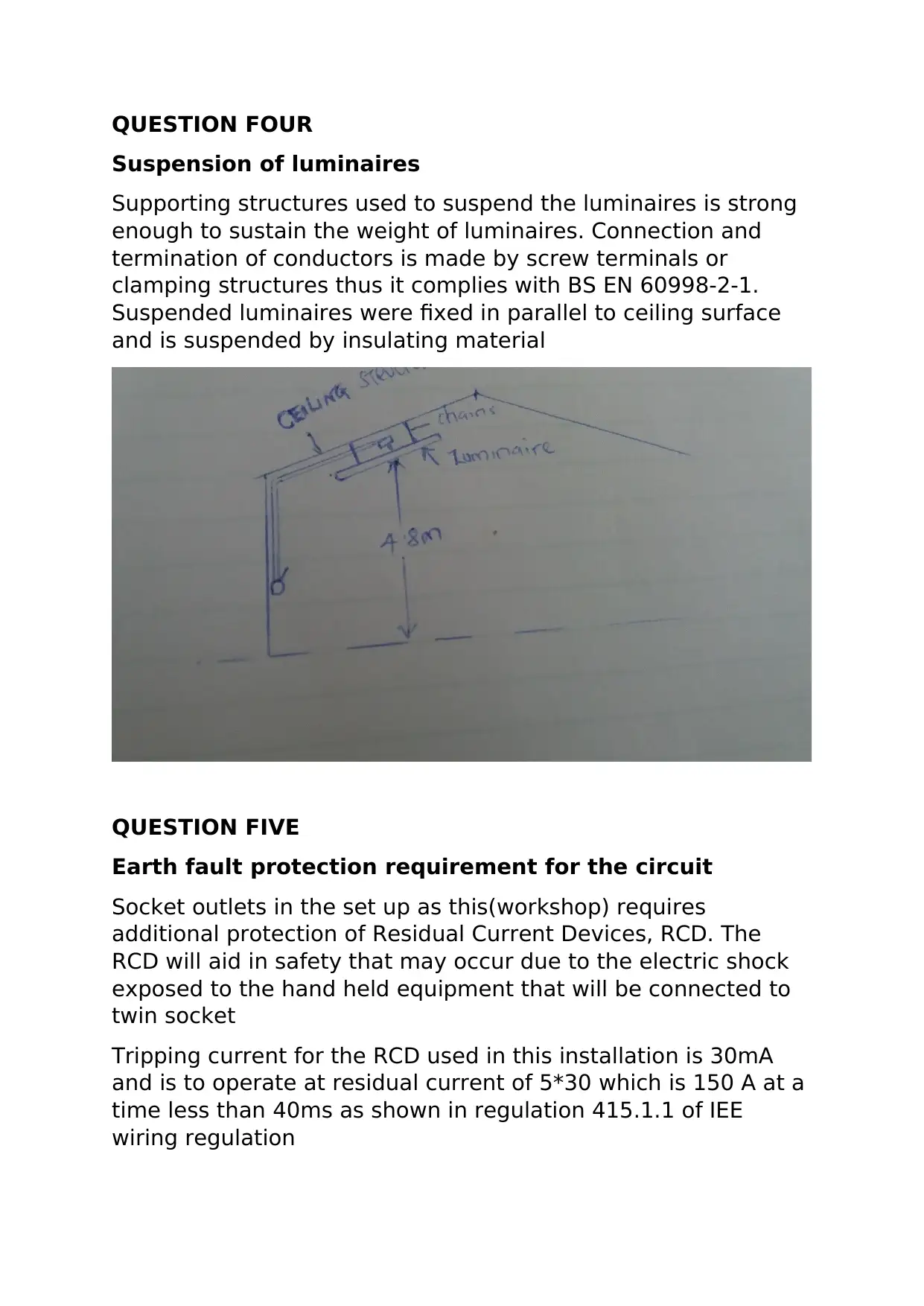
Suspension of luminaires
Supporting structures used to suspend the luminaires is strong
enough to sustain the weight of luminaires. Connection and
termination of conductors is made by screw terminals or
clamping structures thus it complies with BS EN 60998-2-1.
Suspended luminaires were fixed in parallel to ceiling surface
and is suspended by insulating material
QUESTION FIVE
Earth fault protection requirement for the circuit
Socket outlets in the set up as this(workshop) requires
additional protection of Residual Current Devices, RCD. The
RCD will aid in safety that may occur due to the electric shock
exposed to the hand held equipment that will be connected to
twin socket
Tripping current for the RCD used in this installation is 30mA
and is to operate at residual current of 5*30 which is 150 A at a
time less than 40ms as shown in regulation 415.1.1 of IEE
wiring regulation
Requirements for height and provision of socket outlets
The building regulation require the socket outlets be installed in
a position easily accessible by users. To satisfy this
requirement socket outlets are installed at a minimum height of
450 mm
As for the number of socket outlets, sufficient number is
installed so that equipment using them can be reasonable
access, taking into account length of a flexible cable fitted to
the portable equipment.
QUESTION SIX
Design current
Taking power of a single-phase air compressor to be 2.5hp,
with a power factor of 0.78, and a 75 percent efficiency. Design
current, Ib is calculated as shown below
P=V*Ib*cos Ø
0.75×2.5×746 w= 230 V× Ib×0.78
Ib= (746×2.5×0.75)/(230×0.78)
= 7.8 A
QUESTION SEVEN
a) Circuit design
3 phase power supply to the lift rated 400V, 3kW and a power
factor 0.85
Circuit type – three phase radial
Power= √3*V×I×P.F
Design current, Ib is thus
Ib= √3*3000/400×0.85
=15.28 A
⊘ This is a preview!⊘
Do you want full access?
Subscribe today to unlock all pages.

Trusted by 1+ million students worldwide
For the circuit to operate normally, Current rating of
overcurrent protecting device, In>Ib
Installation method B is preferred for this installation
Type B circuit breakers to BS EN 60898 and RCBOs used with
In=20 A
as shown in appendix 4, BS7671 for this type of cable, and the
ambient temperature.
Value of current tabulated, It is calculated by the formula below
It=In/Ca*Cg*Ci*Cc
Ca is a factor for ambient temperature and from Table 6A on
onsite guide, Ca is 1.0 for an ambient temperature of 30
degrees.
Cg is a factor for grouping, from table 6C of onsite guide, Cg for
4 circuits is 0.80
Ci=Cc=1
It= 20/1.0*0.8
= 25 A
From table 4D2A reference method used will be B, cable used
will be of cross sectional 4mm2 for copper conductor
b) CPC calculations
Adiabatic formula, S= I*√(t)/k
Where I is the fault current
S is nominal cross-sectional area of conductor
T is operating time of disconnecting device upon fault
current
K is factor, as shown table 54.2 to 54.6 of BS7671
From fig 3A4 of IET wiring regulation
Fault current I of type B breaker corresponding to In of 20A is
100 A
Paraphrase This Document
Need a fresh take? Get an instant paraphrase of this document with our AI Paraphraser
Values of K from table 54.3 of BS 7671 is 54.3 (single core) and
the approximate tripping time of 2 seconds
S= (100*√2)/54.3= 2.6 mm2
From table 54.7 of BS7671, if S is equal or less than 16, the
cross-sectional area the minimum cross-sectional of CPC is
equal to S
Thus, minimum size of CPC is 2mm2
Question eight
a) Lighting circuit
Circuit type- single phase ring
Design current Ib will be calculated using the highest power
consumed by the one of the lighting equipment that is 2×42 W
(twin LED floodlight)
P= V*I*cos Ø
Lights are resistive loads thus a P.F is 1
Ib=84/230 v= 0.365 A
For the circuit to operate normally, Current rating of
overcurrent protecting device, In>Ib
Type B circuit breakers to BS EN 60898 and RCBOs used with
In= 6 A
Installation method: B
Number of circuits is four
Type of cable-single core non-sheathed
It=In/Ca*Cg*Ci*Cc
Ca for ambient temperature from Table 4B1 of IET wiring
regulation Ca is 1.03 for 25 degrees
Cg for grouping, from table 6C of onsite guide, Cg for 4 circuits
= 0.80
Ci*Cc=1
It= 6/1.03*0.8
= 7 A
From table 4D2A reference method used will be B, cable used
will of cross sectional 1mm2 for copper conductor
b) CPC calculation
Adiabatic formula, S= I*√(t)/k
Where I is the fault current
S is nominal cross-sectional area of conductor
T is operating time of disconnecting device upon
fault current
K is factor, as shown table 54.2 to 54.6 of BS7671
From fig 3A4 of IET wiring regulation
Fault current I of type B breaker corresponding to In of 6A is 30A
Values of K from table 54.3 of BS 7671 is 54.3 (single core) and
the approximate tripping time of 2 seconds
S= (30*/2)/54.3= 0.78 mm2
From table 54.7 of BS7671, if S is equal or less than 16, the
cross-sectional area the minimum cross sectional of CPC is
equal to S
Thus, minimum size of CPC is 1mm2
QUESTION NINE
Notices, labelling and diagrams for the luminaire installation
⊘ This is a preview!⊘
Do you want full access?
Subscribe today to unlock all pages.

Trusted by 1+ million students worldwide
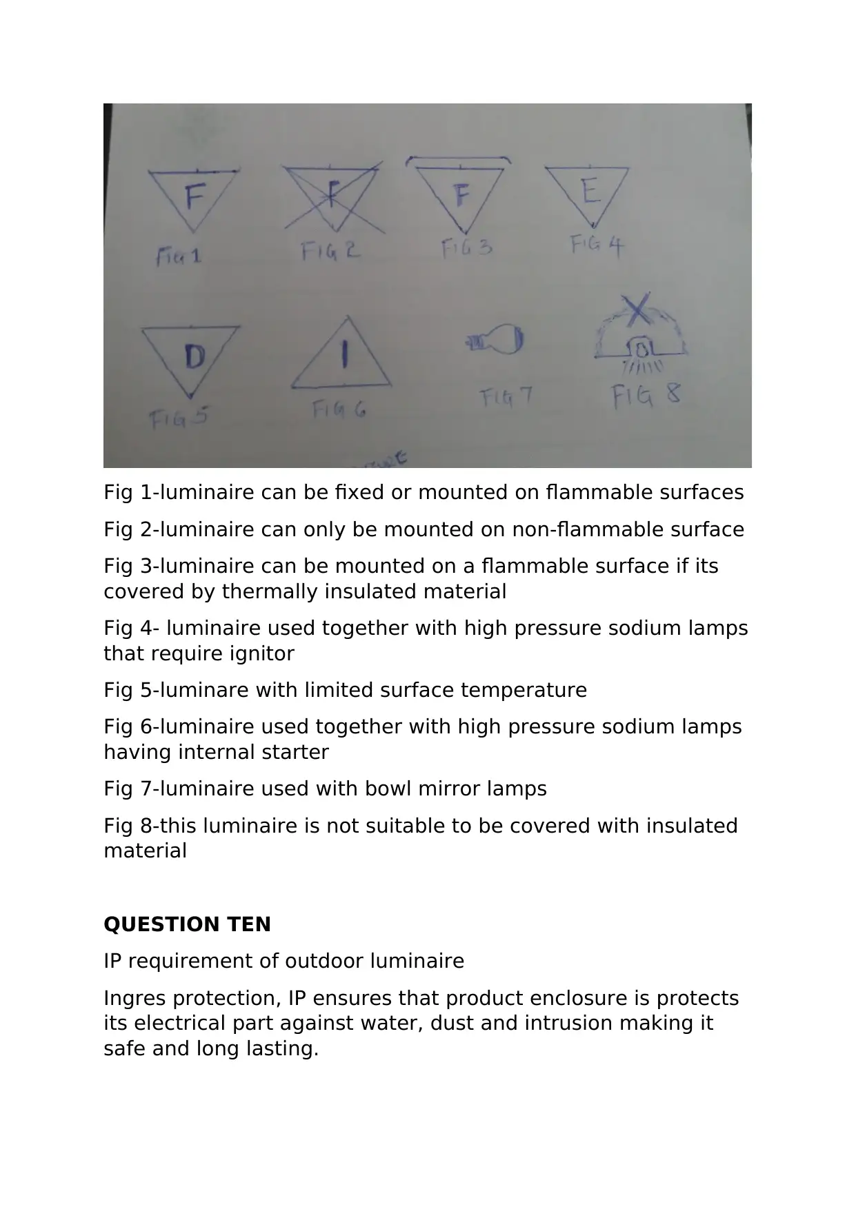
Fig 1-luminaire can be fixed or mounted on flammable surfaces
Fig 2-luminaire can only be mounted on non-flammable surface
Fig 3-luminaire can be mounted on a flammable surface if its
covered by thermally insulated material
Fig 4- luminaire used together with high pressure sodium lamps
that require ignitor
Fig 5-luminare with limited surface temperature
Fig 6-luminaire used together with high pressure sodium lamps
having internal starter
Fig 7-luminaire used with bowl mirror lamps
Fig 8-this luminaire is not suitable to be covered with insulated
material
QUESTION TEN
IP requirement of outdoor luminaire
Ingres protection, IP ensures that product enclosure is protects
its electrical part against water, dust and intrusion making it
safe and long lasting.
Paraphrase This Document
Need a fresh take? Get an instant paraphrase of this document with our AI Paraphraser
For security lighting it should be protected and be durable.
When looking for security luminaire product of IP44-IP68 is
chosen. If the outdoor luminaire is placed in unsheltered place,
Floodlight of IP65 is chosen as its dust tight and is protected
from water jets.
QUESTION ELEVEN
a) Gas supply metal pipes
Water supply metal pipes
Distribution board
Exposed metal parts appliances
b) Protective bonding minimises the potential difference
between conductive parts when a fault occurs. The
bonding equalises the potential between extraneous
conductive part and exposed conductive parts
c) Air conditioning systems
Metal gas pipes
Metal water pipes
QUESTION TWELVE
Prospective fault current- its that overcurrent that flows when
earth fault or short circuit fault occurs in electrical systems
QUESTION THIRTEEN
Prospective fault current is highest at the origin of installation,
as at this point impedance is at its lowest level. If PFC is not
high at the main, then it means everywhere else is okay. From
ohms law, I=V/R it can seen that the higher the resistance the
lesser the current, the farther you move from the main
resistance keep increasing
QUESTION FOURTEEN
ICN- its breaking capacity rating of a circuit breaker and its a
maximum fault current that circuit break can successfully
interrupt without it being damaged
ICS- its the maximum fault current that a break successfully
interrupts after which the breaker is rendered unusable until
repaired or tested for normal operation
QUESTION FIFTEEN
Coordination of protective devices- its the process that
involves selecting and arranging protective devices to restrict
overcurrent to small area.
Coordination of protective devices aids in determining breaker
and relay setting also to determine sizes of fuses.
Discrimination- this is the coordination of protective devices
so that a fault appearing at specific zone of the power system is
cleared by a protective device responsible for that zone alone.
QUESTION SIXTEEN
All electrical installations deteriorate with time, and it is
recommended to perform some inspection and testing. The
rate at which installation deteriorates depends on some factors
such as nature of activities performed in the area of
installation, and the degree of wear and tear that can occur in
the normal use
For this installation maximum period to first inspection and
testing is 3 years
⊘ This is a preview!⊘
Do you want full access?
Subscribe today to unlock all pages.

Trusted by 1+ million students worldwide

1 out of 10
Your All-in-One AI-Powered Toolkit for Academic Success.
+13062052269
info@desklib.com
Available 24*7 on WhatsApp / Email
![[object Object]](/_next/static/media/star-bottom.7253800d.svg)
Unlock your academic potential
Copyright © 2020–2026 A2Z Services. All Rights Reserved. Developed and managed by ZUCOL.