Practical Analysis of Electrical Power and Machines Systems
VerifiedAdded on 2021/04/24
|14
|956
|95
Practical Assignment
AI Summary
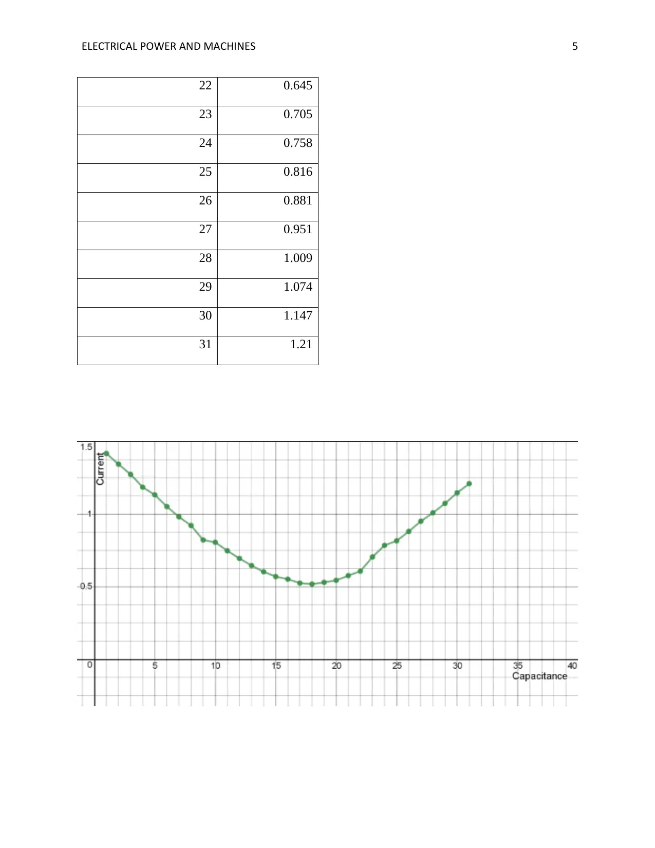
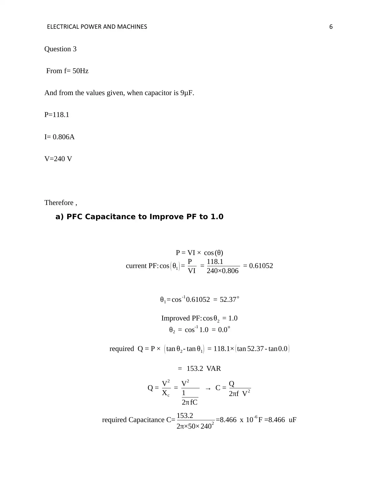
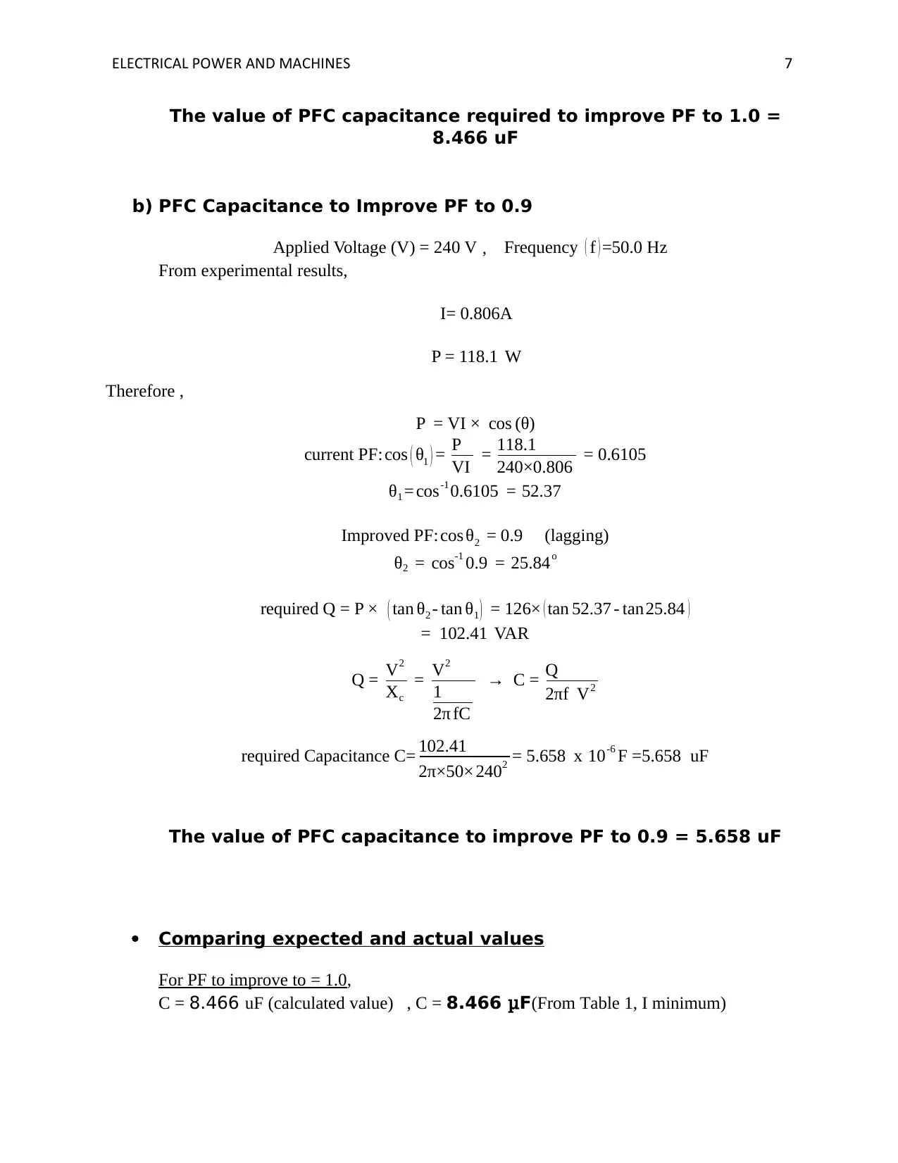
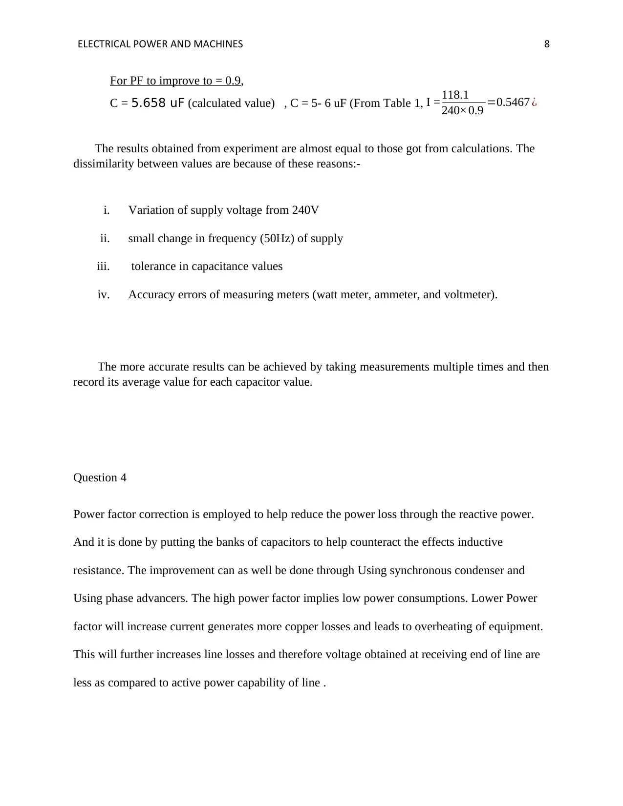
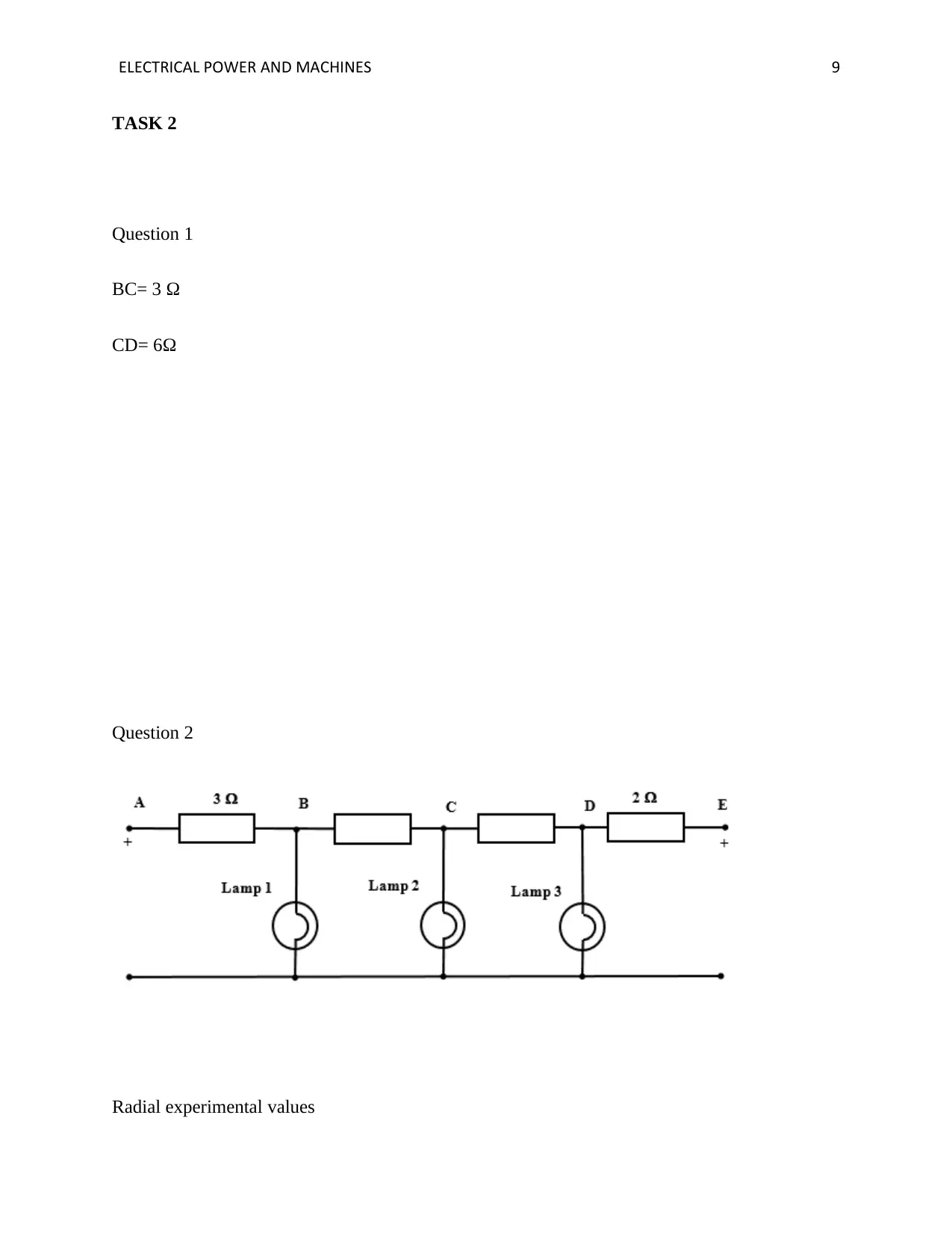
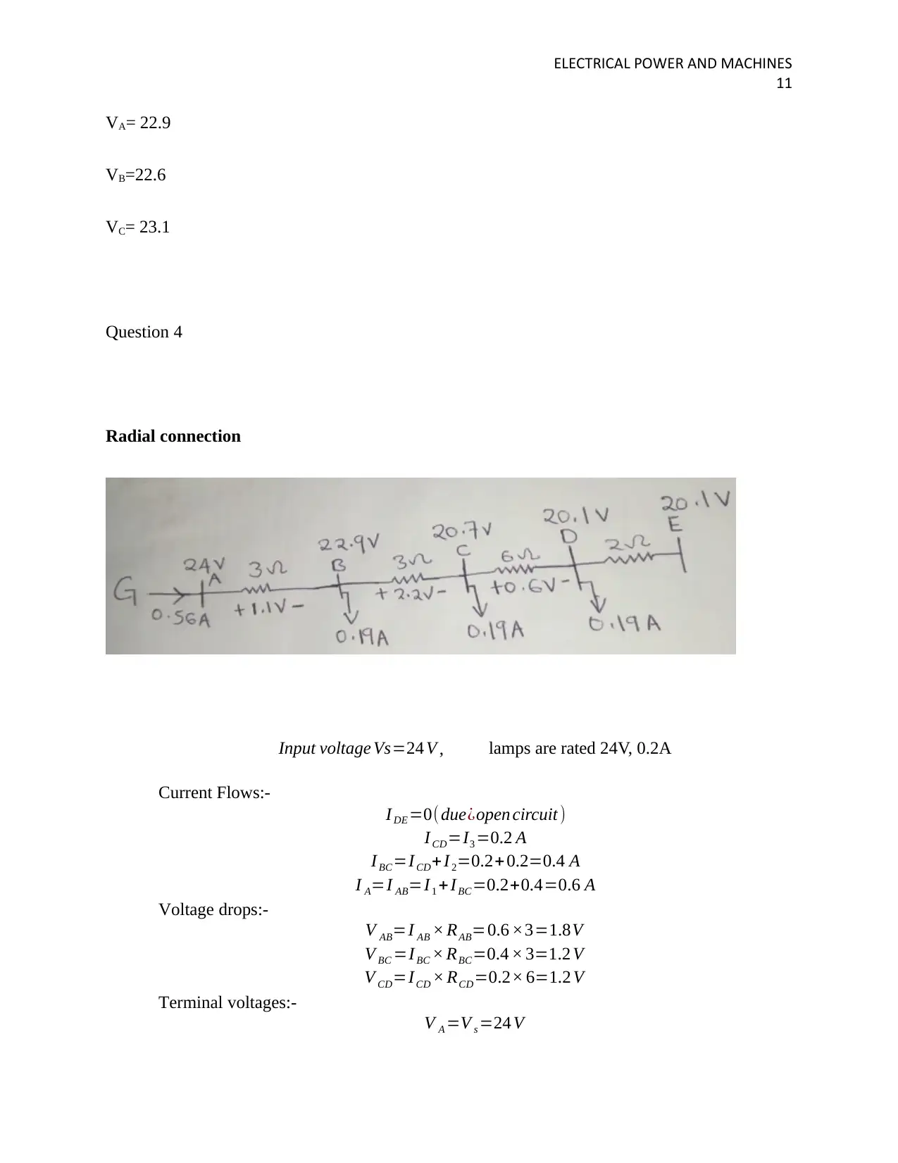
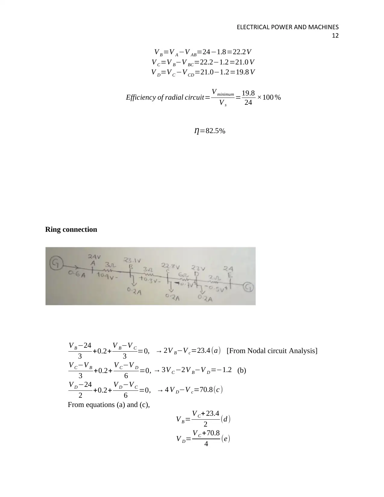
This assignment on electrical power and machines presents a detailed analysis of practical experiments and theoretical concepts. The first task involves analyzing the impact of capacitors on power factor, including experimental data on voltage, current, and power under varying capacitance. It explores power factor correction techniques and compares expected versus actual values, discussing potential sources of error. The second task focuses on circuit analysis, comparing radial and ring connections. It includes experimental values for current and voltage drops in both configurations, and provides a comparison of their advantages and disadvantages. The assignment highlights the impact of different connection methods on voltage regulation and power distribution, concluding with a discussion of potential experimental errors and their impact on results.

Running head: ELECTRICAL POWER AND MACHINES 0
ELECTRICAL POWER AND MACHINES
By Name
Course
Instructor
Institution
Location
Date
ELECTRICAL POWER AND MACHINES
By Name
Course
Instructor
Institution
Location
Date
Paraphrase This Document
Need a fresh take? Get an instant paraphrase of this document with our AI Paraphraser

ELECTRICAL POWER AND MACHINES 2
TASK 1
Question 1
capacitor (micro-farad)
Switch off (no capactor)
power / Watts Current / Amps Voltage/ Volts
118.6 1.418 241.3
1 117.4 1.344 241.15
2 118.5 1.274 241.3
3 117.6 1.186 240.4
4 118 1.133 241.1
5 118.1 1.052 240.9
6 117.9 0.981 240.3
7 118.5 0.922 241.1
8 118.1 0.822 241.2
9 118.1 0.806 240
10 118.2 0.748 240
11 118.2 0.695 240.1
12 118.1 0.646 240.3
13 118.1 0.603 240.1

ELECTRICAL POWER AND MACHINES 3
14 117.5 0.57 240.6
15 118.2 0.552 240.7
16 118.6 0.525 241.3
17 119.1 0.518 241.7
18 118.8 0.53 241.6
19 119.4 0.544 242
20 119.3 0.576 241.7
21 117.3 0.607 240.8
22 117.2 0.645 240.8
23 117.2 0.705 240.8
24 114.7 0.758 239.3
25 116.3 0.816 240.3
26 117.1 0.881 240.5
27 116.9 0.951 240.6
28 117.4 1.009 240.3
29 117 1.074 240.3
30 117.3 1.147 240.3
31 117.5 1.21 240.5
Question 2
capacitor (micro-farad) Current / Amps
⊘ This is a preview!⊘
Do you want full access?
Subscribe today to unlock all pages.

Trusted by 1+ million students worldwide

ELECTRICAL POWER AND MACHINES 4
Switch off (no
capacitor)
1.418
1 1.344
2 1.274
3 1.186
4 1.133
5 1.052
6 0.981
7 0.922
8 0.822
9 0.806
10 0.748
11 0.695
12 0.646
13 0.603
14 0.57
15 0.552
16 0.525
17 0.518
18 0.53
19 0.544
20 0.576
21 0.607
Switch off (no
capacitor)
1.418
1 1.344
2 1.274
3 1.186
4 1.133
5 1.052
6 0.981
7 0.922
8 0.822
9 0.806
10 0.748
11 0.695
12 0.646
13 0.603
14 0.57
15 0.552
16 0.525
17 0.518
18 0.53
19 0.544
20 0.576
21 0.607
Paraphrase This Document
Need a fresh take? Get an instant paraphrase of this document with our AI Paraphraser

ELECTRICAL POWER AND MACHINES 5
22 0.645
23 0.705
24 0.758
25 0.816
26 0.881
27 0.951
28 1.009
29 1.074
30 1.147
31 1.21
22 0.645
23 0.705
24 0.758
25 0.816
26 0.881
27 0.951
28 1.009
29 1.074
30 1.147
31 1.21

ELECTRICAL POWER AND MACHINES 6
Question 3
From f= 50Hz
And from the values given, when capacitor is 9μF.
P=118.1
I= 0.806A
V=240 V
Therefore ,
a) PFC Capacitance to Improve PF to 1.0
P = VI × cos (θ)
current PF: cos ( θ1 ) = P
VI = 118.1
240×0.806 = 0.61052
θ1 = cos-10.61052 = 52.37o
Improved PF: cos θ2 = 1.0
θ2 = cos-1 1.0 = 0.0o
required Q = P × ( tan θ2 - tan θ1 ) = 118.1× ( tan 52.37 - tan0.0 )
= 153.2 VAR
Q = V2
Xc
= V2
1
2π fC
→ C = Q
2πf V2
required Capacitance C= 153.2
2π×50× 2402 =8.466 x 10⁻⁶ F =8.466 uF
⊘ This is a preview!⊘
Do you want full access?
Subscribe today to unlock all pages.

Trusted by 1+ million students worldwide

ELECTRICAL POWER AND MACHINES 7
The value of PFC capacitance required to improve PF to 1.0 =
8.466 uF
b) PFC Capacitance to Improve PF to 0.9
Applied Voltage (V) = 240 V , Frequency ( f ) =50.0 Hz
From experimental results,
I= 0.806A
P = 118.1 W
Therefore ,
P = VI × cos (θ)
current PF: cos ( θ1 ) = P
VI = 118.1
240×0.806 = 0.6105
θ1 = cos-1 0.6105 = 52.37
Improved PF: cos θ2 = 0.9 (lagging)
θ2 = cos-1 0.9 = 25.84o
required Q = P × ( tan θ2 - tan θ1 ) = 126× ( tan 52.37 - tan25.84 )
= 102.41 VAR
Q = V2
Xc
= V2
1
2π fC
→ C = Q
2πf V2
required Capacitance C= 102.41
2π×50× 2402 = 5.658 x 10⁻⁶ F =5.658 uF
The value of PFC capacitance to improve PF to 0.9 = 5.658 uF
Comparing expected and actual values
For PF to improve to = 1.0,
C = 8.466 uF (calculated value) , C = 8.466 μF(From Table 1, I minimum)
Paraphrase This Document
Need a fresh take? Get an instant paraphrase of this document with our AI Paraphraser

ELECTRICAL POWER AND MACHINES 8
For PF to improve to = 0.9,
C = 5.658 uF (calculated value) , C = 5- 6 uF (From Table 1, I = 118.1
240× 0.9 =0.5467 ¿
The results obtained from experiment are almost equal to those got from calculations. The
dissimilarity between values are because of these reasons:-
i. Variation of supply voltage from 240V
ii. small change in frequency (50Hz) of supply
iii. tolerance in capacitance values
iv. Accuracy errors of measuring meters (watt meter, ammeter, and voltmeter).
The more accurate results can be achieved by taking measurements multiple times and then
record its average value for each capacitor value.
Question 4
Power factor correction is employed to help reduce the power loss through the reactive power.
And it is done by putting the banks of capacitors to help counteract the effects inductive
resistance. The improvement can as well be done through Using synchronous condenser and
Using phase advancers. The high power factor implies low power consumptions. Lower Power
factor will increase current generates more copper losses and leads to overheating of equipment.
This will further increases line losses and therefore voltage obtained at receiving end of line are
less as compared to active power capability of line .

ELECTRICAL POWER AND MACHINES 9
TASK 2
Question 1
BC= 3 Ω
CD= 6Ω
Question 2
Radial experimental values
TASK 2
Question 1
BC= 3 Ω
CD= 6Ω
Question 2
Radial experimental values
⊘ This is a preview!⊘
Do you want full access?
Subscribe today to unlock all pages.

Trusted by 1+ million students worldwide

ELECTRICAL POWER AND MACHINES
10
IA= 0.56 A
I1= 0.1937
I2=0.1858
I3= 0.1737
VA= 22.1
VB=21.0
VC= 20.0
Question 3
Ring experimental values
IA= 0.3 A
IE= 0.29 A
I1= 0.1977
I2=0.1944
I3= 0.1885
10
IA= 0.56 A
I1= 0.1937
I2=0.1858
I3= 0.1737
VA= 22.1
VB=21.0
VC= 20.0
Question 3
Ring experimental values
IA= 0.3 A
IE= 0.29 A
I1= 0.1977
I2=0.1944
I3= 0.1885
Paraphrase This Document
Need a fresh take? Get an instant paraphrase of this document with our AI Paraphraser

ELECTRICAL POWER AND MACHINES
11
VA= 22.9
VB=22.6
VC= 23.1
Question 4
Radial connection
Input voltage Vs=24 V , lamps are rated 24V, 0.2A
Current Flows:-
I DE =0(due¿open circuit )
I CD=I3 =0.2 A
I BC=ICD+ I2=0.2+ 0.2=0.4 A
I A=I AB=I1 + IBC=0.2+0.4=0.6 A
Voltage drops:-
V AB=I AB × RAB=0.6 ×3=1.8V
V BC =I BC × RBC=0.4 × 3=1.2 V
V CD=ICD × RCD=0.2× 6=1.2 V
Terminal voltages:-
V A =V s =24 V

ELECTRICAL POWER AND MACHINES
12
V B =V A −V AB=24−1.8=22.2V
V C=V B−V BC=22.2−1.2=21.0 V
V D=V C −V CD=21.0−1.2=19.8 V
Efficiency of radial circuit= V minimum
V s
=19.8
24 ×100 %
Ƞ=82.5%
Ring connection
V B −24
3 +0.2+ V B−V C
3 =0, → 2V B−V c=23.4 (a) [From Nodal circuit Analysis]
V C−V B
3 +0.2+ V C−V D
6 =0, → 3V C −2V B−V D =−1.2 (b)
V D −24
2 +0.2+ V D −V C
6 =0, → 4 V D−V c=70.8(c )
From equations (a) and (c),
V B = V C+ 23.4
2 (d )
V D= V C +70.8
4 (e)
⊘ This is a preview!⊘
Do you want full access?
Subscribe today to unlock all pages.

Trusted by 1+ million students worldwide
1 out of 14

Your All-in-One AI-Powered Toolkit for Academic Success.
+13062052269
info@desklib.com
Available 24*7 on WhatsApp / Email
Unlock your academic potential
Copyright © 2020–2025 A2Z Services. All Rights Reserved. Developed and managed by ZUCOL.