University Lab Report: Electrical Circuit Measurements, EE 101
VerifiedAdded on 2022/10/16
|5
|954
|486
Report
AI Summary
This lab report details an experiment on electrical circuit measurements, focusing on fundamental concepts and practical applications. The objectives included understanding basic electrical circuits and apparatus, gaining a practical understanding of Ohm’s law, constructing circuits on a breadb...

1
Lab Report 1: Electrical Circuit Measurements
Aims and objectives
This laboratory exercise was carried out to achieve the following aims
1. To understand basic electrical circuits and apparatus such as the digital multimeter
2. To gain a practical understanding of Ohm’s law
3. To construct circuits on a bread board
4. To measure circuit parameters such as currents, resistance and voltages
5. To acquaint with laboratory procedures and standards
Apparatus used
1. Power supply
2. Bread board
3. Digital multimeter
4. Resistors
Procedure
The first part of this laboratory involves familiarization with the uses of the digital
multimeter. The use of the multimeter in the measurement of voltages, currents and resistance
was discussed ion details before commencing on the practical part. The value of the resistor
was then measured with the power supply to the circuit cut off.
Paraphrase This Document
Need a fresh take? Get an instant paraphrase of this document with our AI Paraphraser

2
The second part involved the construction of a series circuit with three different resistances.
The individual resistances, voltages and current through the resistor network were then
measured and recorded. This was done to understand Kirchhoff’s voltage law.
For the third part of the exercise, a parallel network of resistances was constructed to
investigate Kirchhoff’s current law. A total of three resistors were used. The voltages across
the three resistors were measured as well as the currents flowing through the circuit branches.
Finally, a circuit of parallel and series resistor combinations was constructed and voltage and
current measurements carried out.
While taking measurements, the multimeter was connected across the resistor under
investigation while the multimeter was connected in series with the resistor for current
measurements.
Results and discussion
Multimeter:
To obtain the internal resistance of the multimeter, its two measuring probes were connected
together. The recorded resistance was 0.2 Ohms. It was observed that the multimeter gave
unexpected results whenever it was connected inappropriately. Besides, the fuse blew when
the multimeter was connected across a component during current measurement.
Bread board
The bread board is a temporary circuit board. Electrical components can be inserted to
construct an electric circuit and removed whenever necessary. All the circuits were made on
the bread board and connected to the power supply.
Experiment 1: Resistance measurement

3
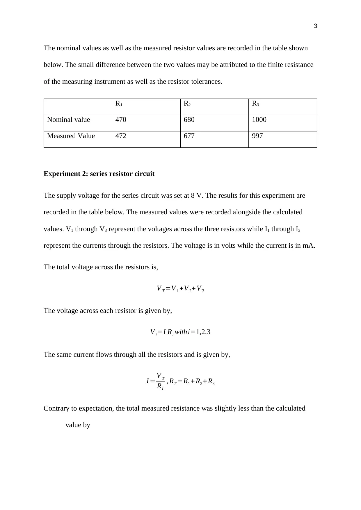
The nominal values as well as the measured resistor values are recorded in the table shown
below. The small difference between the two values may be attributed to the finite resistance
of the measuring instrument as well as the resistor tolerances.
R1 R2 R3
Nominal value 470 680 1000
Measured Value 472 677 997
Experiment 2: series resistor circuit
The supply voltage for the series circuit was set at 8 V. The results for this experiment are
recorded in the table below. The measured values were recorded alongside the calculated
values. V1 through V3 represent the voltages across the three resistors while I1 through I3
represent the currents through the resistors. The voltage is in volts while the current is in mA.
The total voltage across the resistors is,
V T =V 1 +V 2+ V 3
The voltage across each resistor is given by,
V i=I Ri withi=1,2,3
The same current flows through all the resistors and is given by,
I = V T
RT
, RT =R1 +R2 + R3
Contrary to expectation, the total measured resistance was slightly less than the calculated
value by
⊘ This is a preview!⊘
Do you want full access?
Subscribe today to unlock all pages.

Trusted by 1+ million students worldwide

4
4 ohms. To calculate the total current, ohm’s law was applied giving 3.7 mA. The measured
value was 0.02 mA greater than the calculated value due to the lower measured resistance.
Ohm’s law was also used to calculate the voltage drops across the resistors. The circuit was
observed to obey Kirchhoff’s voltage law as the sum of the voltage drops across the resistors
was almost equal to the total supply voltage.
Experiment 3: Resistors in parallel
The values of resistance remain as recorded previously. However, the currents through the
resistors as well as the voltages across the voltages change. The total resistance also changes
and is no longer a simple addition. The total resistance is given by the following equation,
1
RT
= 1
R1
+ 1
R2
+ 1
R3
RT =( 1
R1
+ 1
R2
+ 1
R3
)
−1
= V
I
The total current supplied by the power source is given by,
I =I1+ I2 + I3
The individual currents are given by,
I i= V
Ri
withi=1,2,3
Contrary to expectation, the measured resistance was 0.05 ohms less than the calculated
value. The total current was calculated from ohm’s law and found to be 18.2 mA. However,
the measured value was greater by about 0.2 mA. Ohm’s law was also used to compute the
voltage across the resistances. It was found that the voltage across the resistances was almost
the same as the supply voltage. This is why buildings have their electrical loads connected in
parallel with the supply.
Paraphrase This Document
Need a fresh take? Get an instant paraphrase of this document with our AI Paraphraser

5
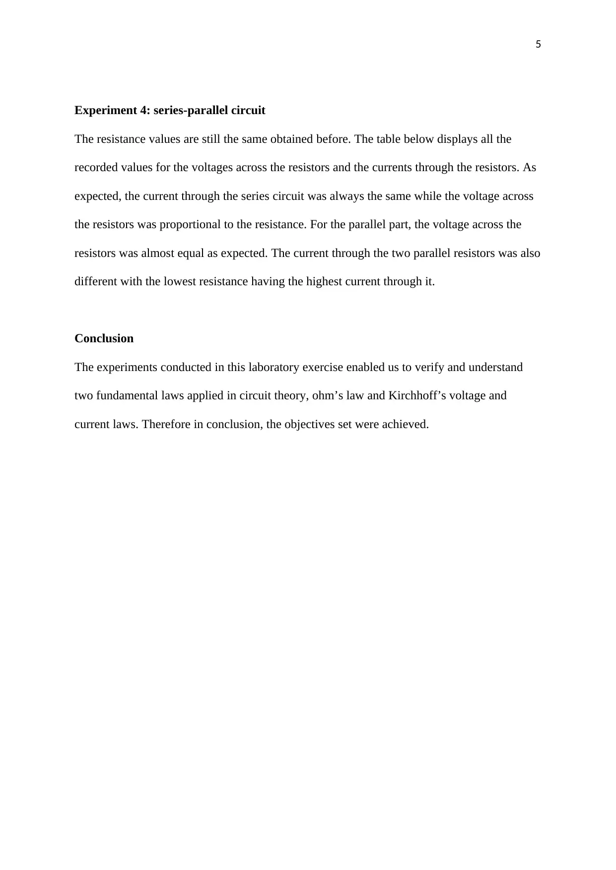
Experiment 4: series-parallel circuit
The resistance values are still the same obtained before. The table below displays all the
recorded values for the voltages across the resistors and the currents through the resistors. As
expected, the current through the series circuit was always the same while the voltage across
the resistors was proportional to the resistance. For the parallel part, the voltage across the
resistors was almost equal as expected. The current through the two parallel resistors was also
different with the lowest resistance having the highest current through it.
Conclusion
The experiments conducted in this laboratory exercise enabled us to verify and understand
two fundamental laws applied in circuit theory, ohm’s law and Kirchhoff’s voltage and
current laws. Therefore in conclusion, the objectives set were achieved.
1 out of 5
Related Documents

Your All-in-One AI-Powered Toolkit for Academic Success.
+13062052269
info@desklib.com
Available 24*7 on WhatsApp / Email
Unlock your academic potential
© 2024 | Zucol Services PVT LTD | All rights reserved.