Electrical Technology and Applications: Workshop Motor Control Systems
VerifiedAdded on 2022/10/11
|18
|4071
|26
Practical Assignment
AI Summary
This assignment addresses electrical technology and applications, focusing on motor control systems in a workshop setting. It begins with the design of a start/stop/retain control circuit for a 3-phase drilling machine or lathe, including the operational principles of electromagnetic relays and examples of commercial relays/contactors. The assignment then explores variable speed drives (VSDs) for controlling the speed of a conveyor line, detailing their operation, components, and application, along with a schematic diagram and discussion of advantages, such as energy efficiency and improved motor performance. Finally, the assignment considers an alternative AC to DC motor control system, focusing on thyristor and transistor H-bridge drive systems, including their operation, advantages, and relevant diagrams. Research evidence and practical examples support the explanations throughout, offering a comprehensive overview of motor control techniques in industrial applications, with a focus on safety, efficiency, and performance.
ELECTRICAL TECHNOLOGY AND APPLICATIONS
Task 4
From workshop audit you have been asked to:
a) Draw a start/stop/retain control circuit that could be used for the safe and
emergency operation of a 3phase drilling machine or lathe in the workshop.
b) Describe how the circuit and relay /contactor would operate for the machine.
Include the principles of operation for electromagnetic mechanical relay.
c) Describe with an example, what types of commercial relays/contactor could be
selected for the task.
Solutions
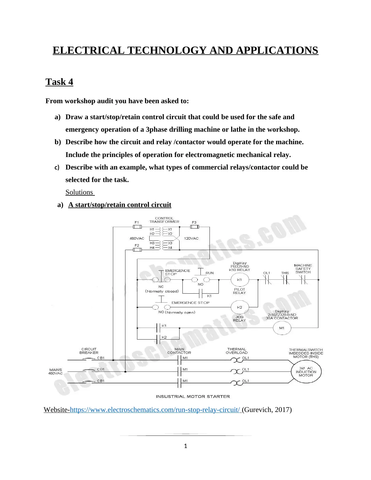
a) A start/stop/retain control circuit
Website-https://www.electroschematics.com/run-stop-relay-circuit/ (Gurevich, 2017)
1
Task 4
From workshop audit you have been asked to:
a) Draw a start/stop/retain control circuit that could be used for the safe and
emergency operation of a 3phase drilling machine or lathe in the workshop.
b) Describe how the circuit and relay /contactor would operate for the machine.
Include the principles of operation for electromagnetic mechanical relay.
c) Describe with an example, what types of commercial relays/contactor could be
selected for the task.
Solutions
a) A start/stop/retain control circuit
Website-https://www.electroschematics.com/run-stop-relay-circuit/ (Gurevich, 2017)
1
Paraphrase This Document
Need a fresh take? Get an instant paraphrase of this document with our AI Paraphraser
The working of the circuit above is as follows. The circuit contains two emergence stop buttons.
When the normally open (NO) emergence stop is pressed, K1 picks up, “shorts” or “seals” the
Run contacts and powers the load—when the Run pushbutton is released, the K1 contact (also
called “holding contact”) conducts instead of the pushbutton so that operation continues.
The second emergence button when pressed, the normally closed (NC), drops the relay and thus
the power from the load is removed and therefore no power supply in the circuit. This loss of
power in addition drops K1 so it cannot automatically restart when power is resumed (Milica
Pejanovic -Djurisc, 2012).
The whole circuit contains relay contact to power the load so that the emergence pushbuttons 1
and 2 do not conduct load current. This relay con handle up to 133 kW of power.
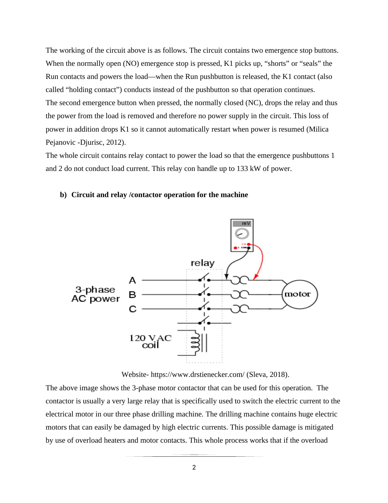
b) Circuit and relay /contactor operation for the machine
Website- https://www.drstienecker.com/ (Sleva, 2018).
The above image shows the 3-phase motor contactor that can be used for this operation. The
contactor is usually a very large relay that is specifically used to switch the electric current to the
electrical motor in our three phase drilling machine. The drilling machine contains huge electric
motors that can easily be damaged by high electric currents. This possible damage is mitigated
by use of overload heaters and motor contacts. This whole process works that if the overload
2
When the normally open (NO) emergence stop is pressed, K1 picks up, “shorts” or “seals” the
Run contacts and powers the load—when the Run pushbutton is released, the K1 contact (also
called “holding contact”) conducts instead of the pushbutton so that operation continues.
The second emergence button when pressed, the normally closed (NC), drops the relay and thus
the power from the load is removed and therefore no power supply in the circuit. This loss of
power in addition drops K1 so it cannot automatically restart when power is resumed (Milica
Pejanovic -Djurisc, 2012).
The whole circuit contains relay contact to power the load so that the emergence pushbuttons 1
and 2 do not conduct load current. This relay con handle up to 133 kW of power.
b) Circuit and relay /contactor operation for the machine
Website- https://www.drstienecker.com/ (Sleva, 2018).
The above image shows the 3-phase motor contactor that can be used for this operation. The
contactor is usually a very large relay that is specifically used to switch the electric current to the
electrical motor in our three phase drilling machine. The drilling machine contains huge electric
motors that can easily be damaged by high electric currents. This possible damage is mitigated
by use of overload heaters and motor contacts. This whole process works that if the overload
2
heaters connected in series technique become overheated due to current overload the motor
contactor will automatically open thereby de-energizing the contactor by redirecting power to the
motor.
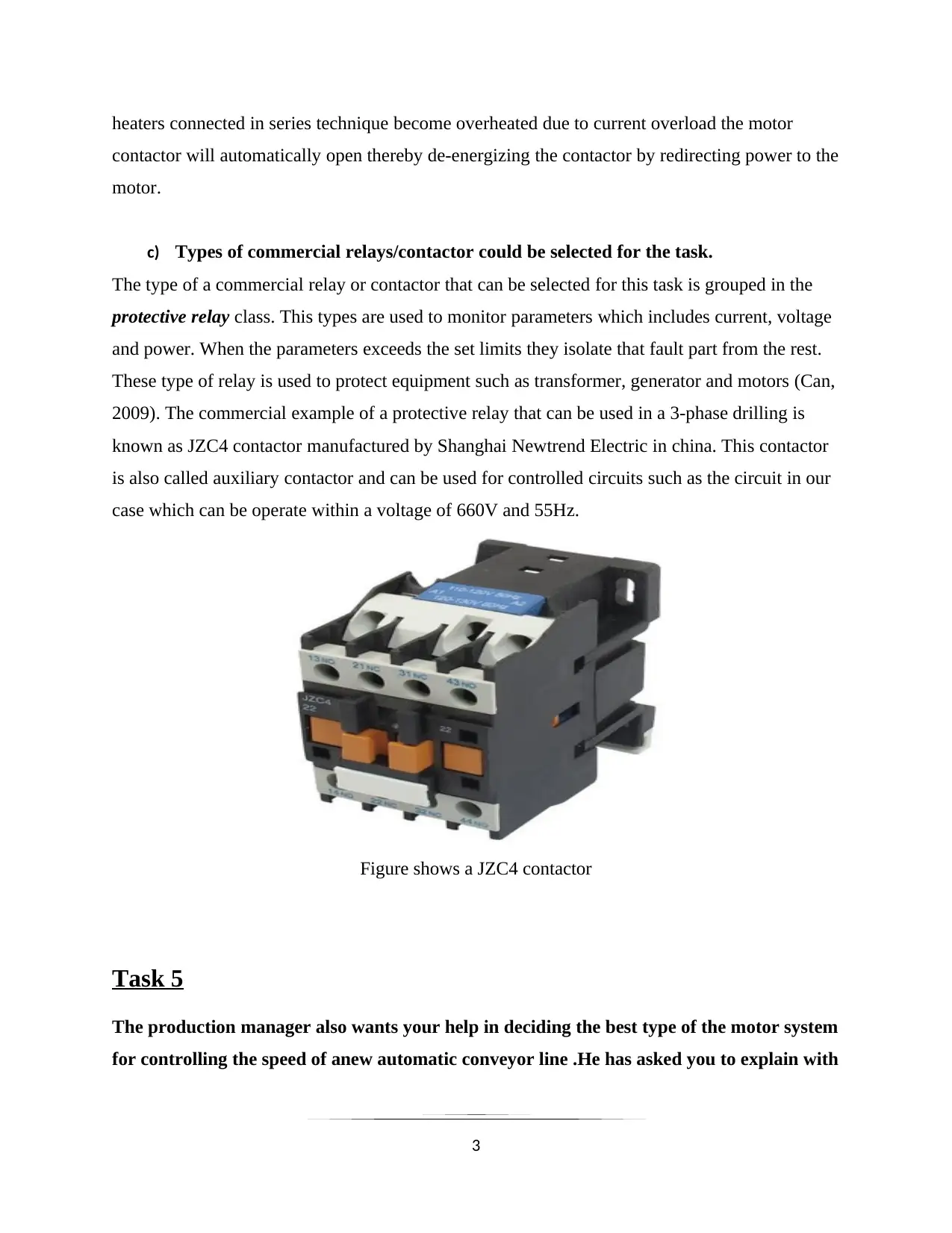
c) Types of commercial relays/contactor could be selected for the task.
The type of a commercial relay or contactor that can be selected for this task is grouped in the
protective relay class. This types are used to monitor parameters which includes current, voltage
and power. When the parameters exceeds the set limits they isolate that fault part from the rest.
These type of relay is used to protect equipment such as transformer, generator and motors (Can,
2009). The commercial example of a protective relay that can be used in a 3-phase drilling is
known as JZC4 contactor manufactured by Shanghai Newtrend Electric in china. This contactor
is also called auxiliary contactor and can be used for controlled circuits such as the circuit in our
case which can be operate within a voltage of 660V and 55Hz.
Figure shows a JZC4 contactor
Task 5
The production manager also wants your help in deciding the best type of the motor system
for controlling the speed of anew automatic conveyor line .He has asked you to explain with
3
contactor will automatically open thereby de-energizing the contactor by redirecting power to the
motor.
c) Types of commercial relays/contactor could be selected for the task.
The type of a commercial relay or contactor that can be selected for this task is grouped in the
protective relay class. This types are used to monitor parameters which includes current, voltage
and power. When the parameters exceeds the set limits they isolate that fault part from the rest.
These type of relay is used to protect equipment such as transformer, generator and motors (Can,
2009). The commercial example of a protective relay that can be used in a 3-phase drilling is
known as JZC4 contactor manufactured by Shanghai Newtrend Electric in china. This contactor
is also called auxiliary contactor and can be used for controlled circuits such as the circuit in our
case which can be operate within a voltage of 660V and 55Hz.
Figure shows a JZC4 contactor
Task 5
The production manager also wants your help in deciding the best type of the motor system
for controlling the speed of anew automatic conveyor line .He has asked you to explain with
3
⊘ This is a preview!⊘
Do you want full access?
Subscribe today to unlock all pages.
Trusted by 1+ million students worldwide
the aid of a diagram , example and research evidence ,a variable speed drive(VSD),in
particular
a) The operation features (how it works)
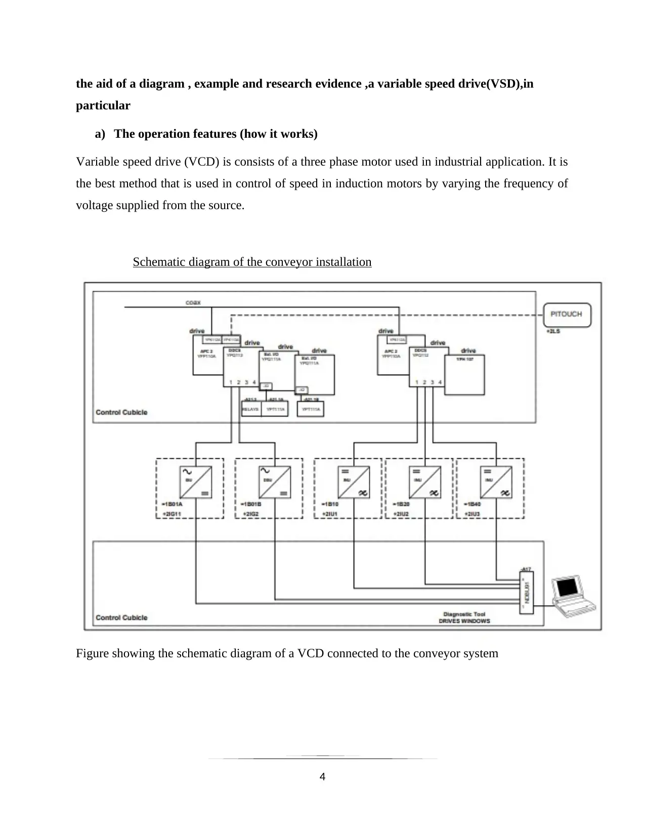
Variable speed drive (VCD) is consists of a three phase motor used in industrial application. It is
the best method that is used in control of speed in induction motors by varying the frequency of
voltage supplied from the source.
Schematic diagram of the conveyor installation
Figure showing the schematic diagram of a VCD connected to the conveyor system
4
particular
a) The operation features (how it works)
Variable speed drive (VCD) is consists of a three phase motor used in industrial application. It is
the best method that is used in control of speed in induction motors by varying the frequency of
voltage supplied from the source.
Schematic diagram of the conveyor installation
Figure showing the schematic diagram of a VCD connected to the conveyor system
4
Paraphrase This Document
Need a fresh take? Get an instant paraphrase of this document with our AI Paraphraser
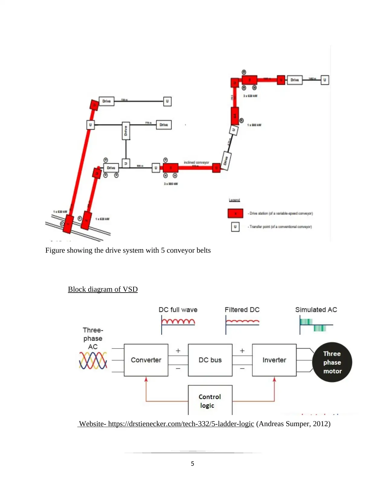
Figure showing the drive system with 5 conveyor belts
Block diagram of VSD
Website- https://drstienecker.com/tech-332/5-ladder-logic (Andreas Sumper, 2012)
5
Block diagram of VSD
Website- https://drstienecker.com/tech-332/5-ladder-logic (Andreas Sumper, 2012)
5
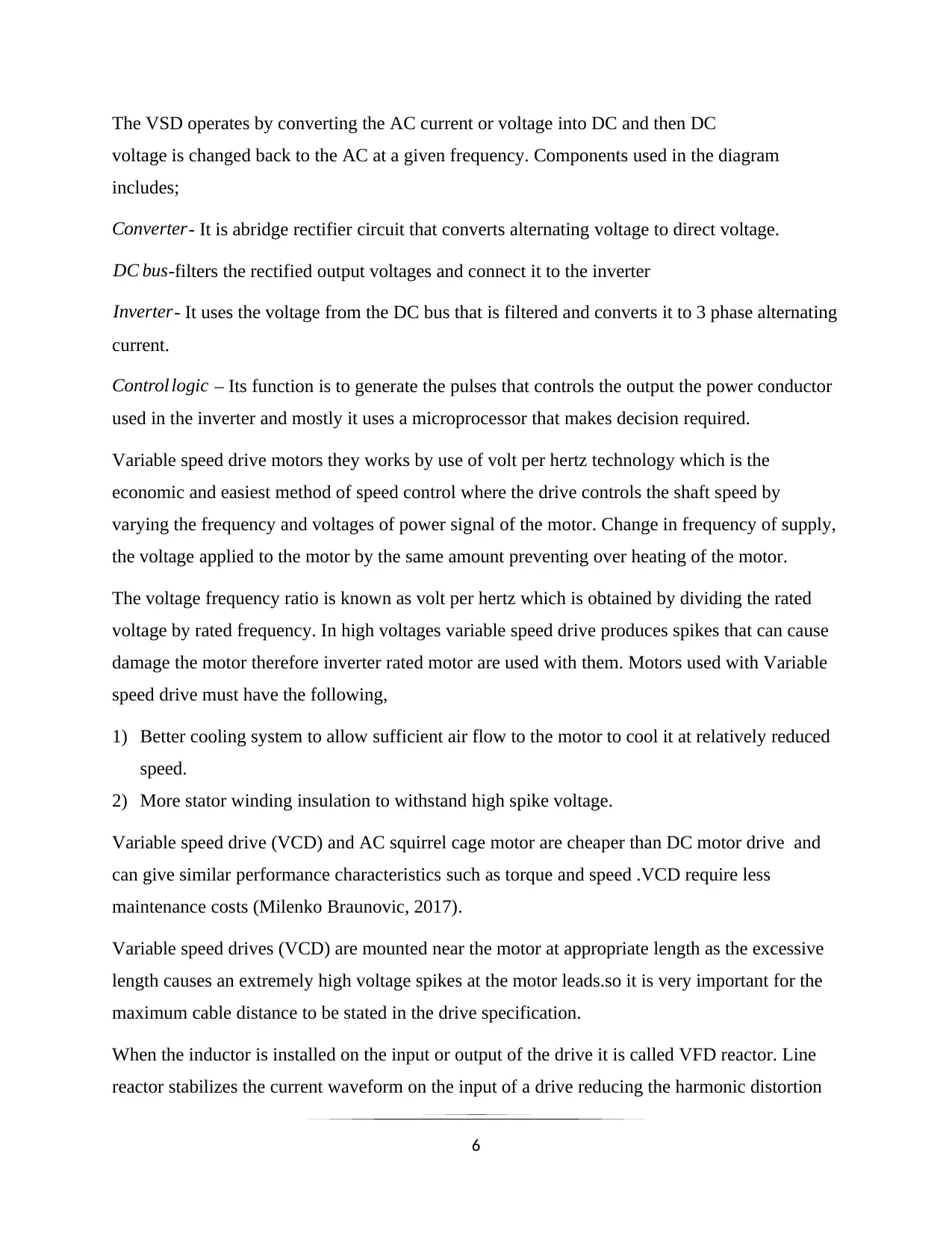
The VSD operates by converting the AC current or voltage into DC and then DC
voltage is changed back to the AC at a given frequency. Components used in the diagram
includes;
Converter- It is abridge rectifier circuit that converts alternating voltage to direct voltage.
DC bus-filters the rectified output voltages and connect it to the inverter
Inverter- It uses the voltage from the DC bus that is filtered and converts it to 3 phase alternating
current.
Control logic – Its function is to generate the pulses that controls the output the power conductor
used in the inverter and mostly it uses a microprocessor that makes decision required.
Variable speed drive motors they works by use of volt per hertz technology which is the
economic and easiest method of speed control where the drive controls the shaft speed by
varying the frequency and voltages of power signal of the motor. Change in frequency of supply,
the voltage applied to the motor by the same amount preventing over heating of the motor.
The voltage frequency ratio is known as volt per hertz which is obtained by dividing the rated
voltage by rated frequency. In high voltages variable speed drive produces spikes that can cause
damage the motor therefore inverter rated motor are used with them. Motors used with Variable
speed drive must have the following,
1) Better cooling system to allow sufficient air flow to the motor to cool it at relatively reduced
speed.
2) More stator winding insulation to withstand high spike voltage.
Variable speed drive (VCD) and AC squirrel cage motor are cheaper than DC motor drive and
can give similar performance characteristics such as torque and speed .VCD require less
maintenance costs (Milenko Braunovic, 2017).
Variable speed drives (VCD) are mounted near the motor at appropriate length as the excessive
length causes an extremely high voltage spikes at the motor leads.so it is very important for the
maximum cable distance to be stated in the drive specification.
When the inductor is installed on the input or output of the drive it is called VFD reactor. Line
reactor stabilizes the current waveform on the input of a drive reducing the harmonic distortion
6
⊘ This is a preview!⊘
Do you want full access?
Subscribe today to unlock all pages.
Trusted by 1+ million students worldwide
and upstream electrical burden. Harmonics are high frequency current and voltages distortions in
power system. VCD produces harmonics as they convert the voltages from AC to DC and back
to AC. Load reactors prevent both over and under voltages tripping problem.
Load reactors connected between the motor and variable speed drives absorbs high voltage
spikes and reduces motor heating and noise thus extending the life of the motor and increases
permissible distance between the motor and the drive Variable speed drives have the best over
the acceleration and retardation time which can be set by setting its ramping time
b) How it can be applied a conveyor
In application of the VSD in a conveyor belt is used as an inverter where it controls the motor
speed torque by input frequency adjustment and voltage of the motor which is induction or
synchronous conveyor belt.
Reasons for the use of VCD drives in belt conveyor
1) Good performance speed synchronization that realizes power balance, and the running
current is very less.
2) Reduces the surge current during start process thus reducing motor thermal loss while
starting the motor frequently increasing working lifespan of motor.
3) The belt conveyor can work at a higher percentage of load without failure.
4) Energy saving; use of the variable frequency drive in the system, the belt speed can be
adjusted automatically as the change of the load. The hydraulic coupler will be removed and
the gear-box will be connected with motor directly, it improves the transmission efficiency
effectively.
With both constant torque applications in the conveyors, the varying torque is applied in devices
such as fans, pumps and blowers but a caution of avoiding not to overloading them must be taken
care of. If the fan drive of a motor is driven at a speed that is faster than the base speed it can
lead to variance in the power requirements to sustain that speed which varies with the cube of the
speed thus consuming more of the power which in return overload the variable speed drive.
Reducing the fan speed let say by a half of the speed it reduces the power required.
7
Paraphrase This Document
Need a fresh take? Get an instant paraphrase of this document with our AI Paraphraser
The VSD restricts the following parameters in a motor which includes; the direction of motion,
speed of the motor and the , torque of the induction motor which is taken at a frequency that is
fixed and voltage from alternating current input and converts it into variable frequency and
voltage alternating current output.
When the variable power supply is applied, the motor produces pulses modulated width current
that results to the production of different in power and frequency supplied to the motor thus
controlling the motor speed accurately over a wide range. This feature enables it to be
appropriate for the conveyor line .Sometimes the variable speed drives are connected with fans
and pumps to vary the speed according to the demand and it saves a lot of energy. Variable speed
drives have a frequency that is fixed and produced from alternating current supply which is
further converted to a variable alternating current supply. This controls the output power which
is mechanical to run the motor efficiently with appropriate speed and this improves its control.
The VSD are components that are adjustable thus they can that can vary the speed of the motor
that is fixed and they are more energy efficient than other devices and they decreases the noise
generated at part of the load to allow fan used in the motor to operate in an unstable condition
that causes violent pulses that can damage the motor and reduce the mechanical wearing out of
conveyor belt and its components.
Due to innovation and invention there is an advancement of the VSD technology that uses solid
state circuit to adjust the voltage and frequency of the motors power as a result speed is varied.
Variable speed drive sometimes takes the place of the starter has they are capable of protecting
overloading in the system. On the other hand the controller used (Microprocessor) controls the
drives to provide extra protection against faults. Variable speed drive provides the comfortable
start of the motor reducing current flow in the brush of the motor and reduces wear of the
conveyor belt.
New Variable speed drive are used as a bypass that selects the speed and do not allow a full
speed running of the motor thus relieving the air pressure and fan speed provided.
8
Task 6
As an alternative to AC system in task 5, you have also been asked to produce a circuit
design that can control the speed and direction of the conveyor such as an Ac to DC motor
thyristor and transistor H-bridge drive system .With reference to appropriate diagram ,an
example and research evidence discuss
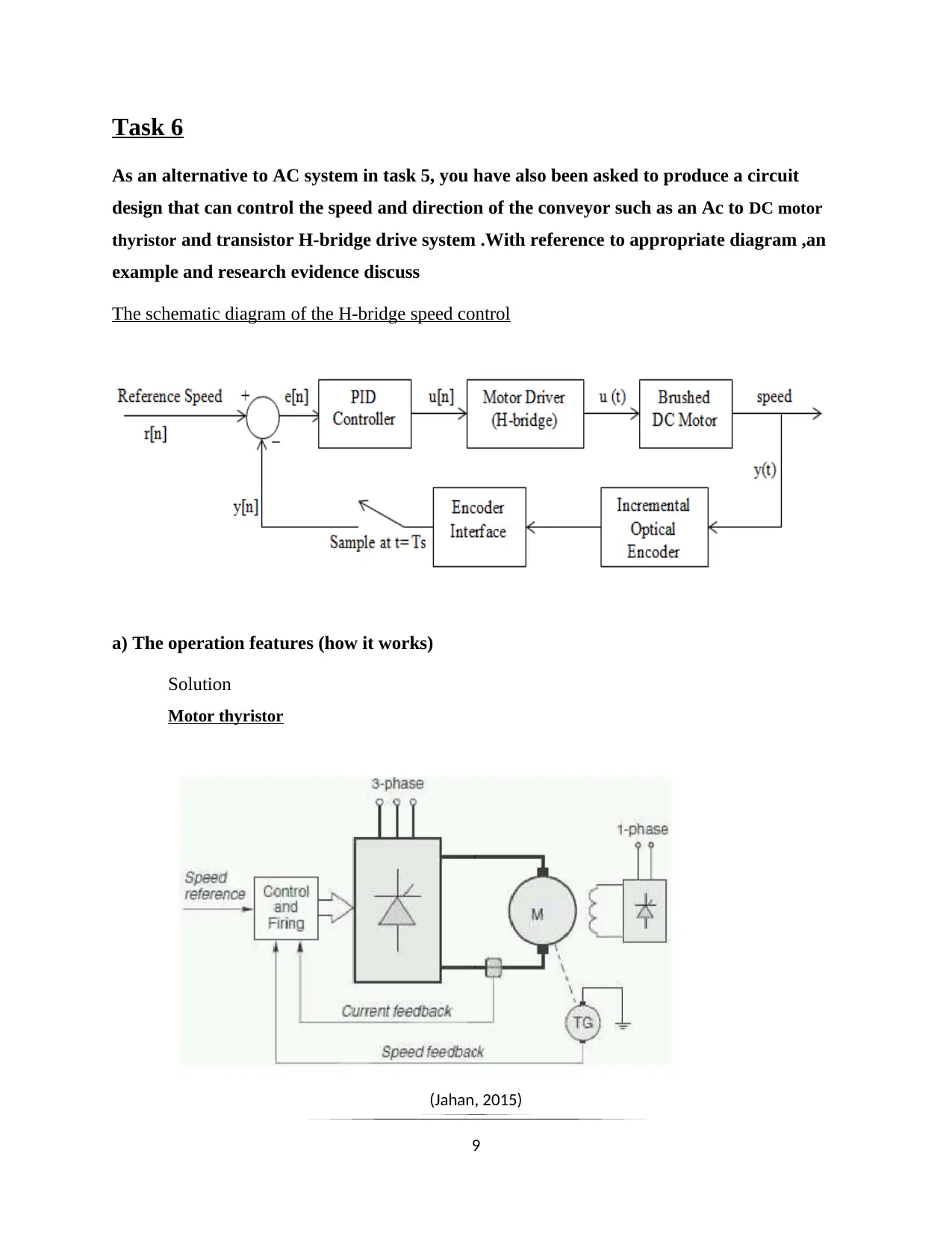
The schematic diagram of the H-bridge speed control
a) The operation features (how it works)
Solution
Motor thyristor
(Jahan, 2015)
9
As an alternative to AC system in task 5, you have also been asked to produce a circuit
design that can control the speed and direction of the conveyor such as an Ac to DC motor
thyristor and transistor H-bridge drive system .With reference to appropriate diagram ,an
example and research evidence discuss
The schematic diagram of the H-bridge speed control
a) The operation features (how it works)
Solution
Motor thyristor
(Jahan, 2015)
9
⊘ This is a preview!⊘
Do you want full access?
Subscribe today to unlock all pages.
Trusted by 1+ million students worldwide
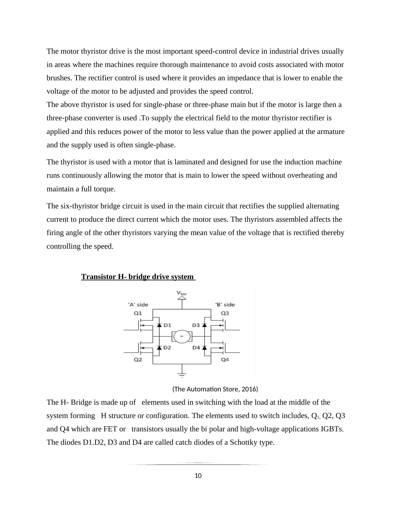
The motor thyristor drive is the most important speed-control device in industrial drives usually
in areas where the machines require thorough maintenance to avoid costs associated with motor
brushes. The rectifier control is used where it provides an impedance that is lower to enable the
voltage of the motor to be adjusted and provides the speed control.
The above thyristor is used for single-phase or three-phase main but if the motor is large then a
three-phase converter is used .To supply the electrical field to the motor thyristor rectifier is
applied and this reduces power of the motor to less value than the power applied at the armature
and the supply used is often single-phase.
The thyristor is used with a motor that is laminated and designed for use the induction machine
runs continuously allowing the motor that is main to lower the speed without overheating and
maintain a full torque.
The six-thyristor bridge circuit is used in the main circuit that rectifies the supplied alternating
current to produce the direct current which the motor uses. The thyristors assembled affects the
firing angle of the other thyristors varying the mean value of the voltage that is rectified thereby
controlling the speed.
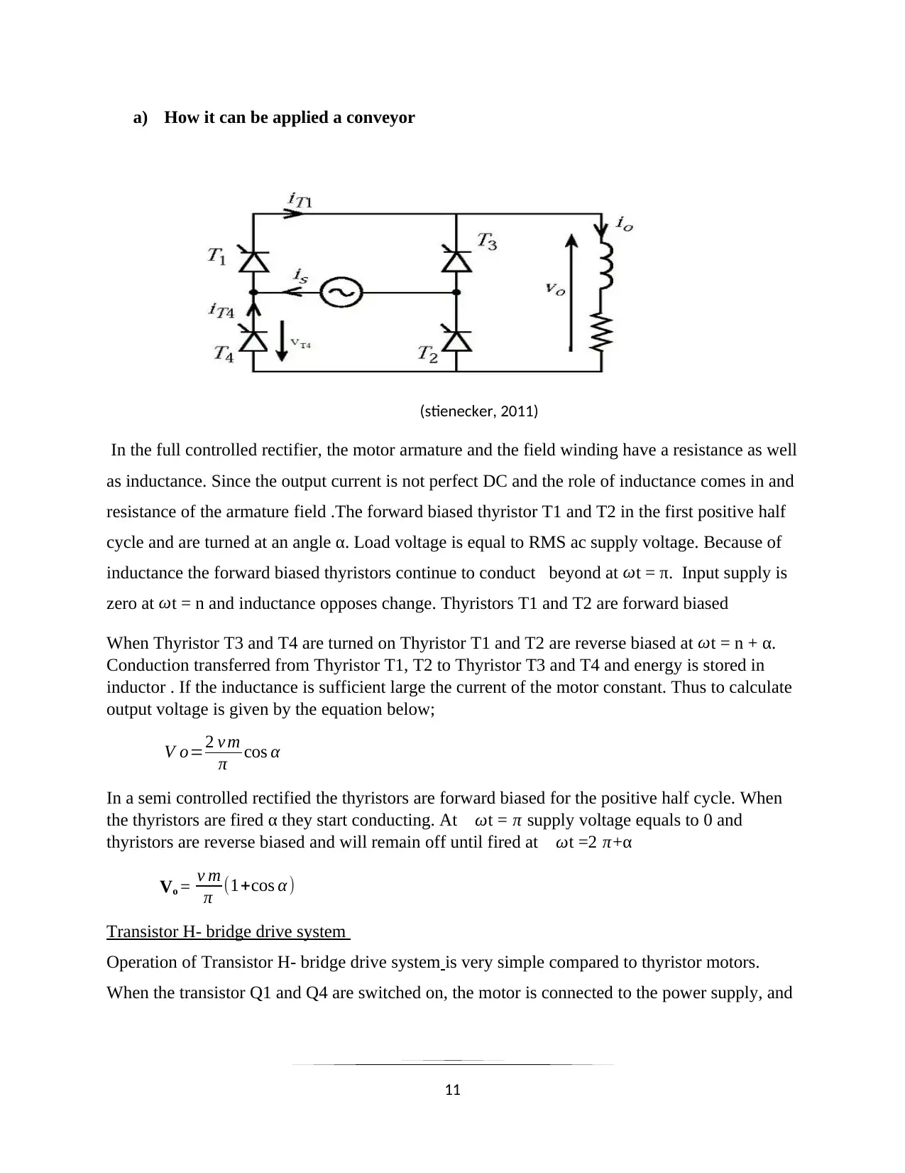
Transistor H- bridge drive system
(The Automation Store, 2016)
The H- Bridge is made up of elements used in switching with the load at the middle of the
system forming H structure or configuration. The elements used to switch includes, Q1, Q2, Q3
and Q4 which are FET or transistors usually the bi polar and high-voltage applications IGBTs.
The diodes D1.D2, D3 and D4 are called catch diodes of a Schottky type.
10
in areas where the machines require thorough maintenance to avoid costs associated with motor
brushes. The rectifier control is used where it provides an impedance that is lower to enable the
voltage of the motor to be adjusted and provides the speed control.
The above thyristor is used for single-phase or three-phase main but if the motor is large then a
three-phase converter is used .To supply the electrical field to the motor thyristor rectifier is
applied and this reduces power of the motor to less value than the power applied at the armature
and the supply used is often single-phase.
The thyristor is used with a motor that is laminated and designed for use the induction machine
runs continuously allowing the motor that is main to lower the speed without overheating and
maintain a full torque.
The six-thyristor bridge circuit is used in the main circuit that rectifies the supplied alternating
current to produce the direct current which the motor uses. The thyristors assembled affects the
firing angle of the other thyristors varying the mean value of the voltage that is rectified thereby
controlling the speed.
Transistor H- bridge drive system
(The Automation Store, 2016)
The H- Bridge is made up of elements used in switching with the load at the middle of the
system forming H structure or configuration. The elements used to switch includes, Q1, Q2, Q3
and Q4 which are FET or transistors usually the bi polar and high-voltage applications IGBTs.
The diodes D1.D2, D3 and D4 are called catch diodes of a Schottky type.
10
Paraphrase This Document
Need a fresh take? Get an instant paraphrase of this document with our AI Paraphraser
a) How it can be applied a conveyor
(stienecker, 2011)
In the full controlled rectifier, the motor armature and the field winding have a resistance as well
as inductance. Since the output current is not perfect DC and the role of inductance comes in and
resistance of the armature field .The forward biased thyristor T1 and T2 in the first positive half
cycle and are turned at an angle α. Load voltage is equal to RMS ac supply voltage. Because of
inductance the forward biased thyristors continue to conduct beyond at ωt = π. Input supply is
zero at ωt = n and inductance opposes change. Thyristors T1 and T2 are forward biased
When Thyristor T3 and T4 are turned on Thyristor T1 and T2 are reverse biased at ωt = n + α.
Conduction transferred from Thyristor T1, T2 to Thyristor T3 and T4 and energy is stored in
inductor . If the inductance is sufficient large the current of the motor constant. Thus to calculate
output voltage is given by the equation below;
V o=2 v m
π cos α
In a semi controlled rectified the thyristors are forward biased for the positive half cycle. When
the thyristors are fired α they start conducting. At ωt = π supply voltage equals to 0 and
thyristors are reverse biased and will remain off until fired at ωt =2 π+α
Vo = v m
π (1+cos α)
Transistor H- bridge drive system
Operation of Transistor H- bridge drive system is very simple compared to thyristor motors.
When the transistor Q1 and Q4 are switched on, the motor is connected to the power supply, and
11
the right lead of the motor connected to ground. Current starts flowing in the motor energizes the
in the forward direction and the shaft starts spine.
When the transistor Q2 and Q3 are turned on, the reverse process occurs thus the motor gets the
opposite direction energy, and results to shaft spinning backwards. The wrong connection of the
switches leads to creation of low-resistance path between power and ground, resulting to short-
circuiting of supply of power through shoot-through. This condition may destroy the bridge, or
something else in your circuit.
Suitable commercial DC motor drive
In dealing with the conveyor system various considerations are taken into account in choosing
the speed control system to be used especially for this case whereby direction and speed will be
controlled using the motor thyristor and the h-bridge transistor. In addition the conveyor system
requires the drive that will guarantee a varying speed and high torque. This two can be provided
by a BLDC motor drive. This drive provides PWM speed controlling technique that is easier
when it comes to variation of speed and require low maintenance.
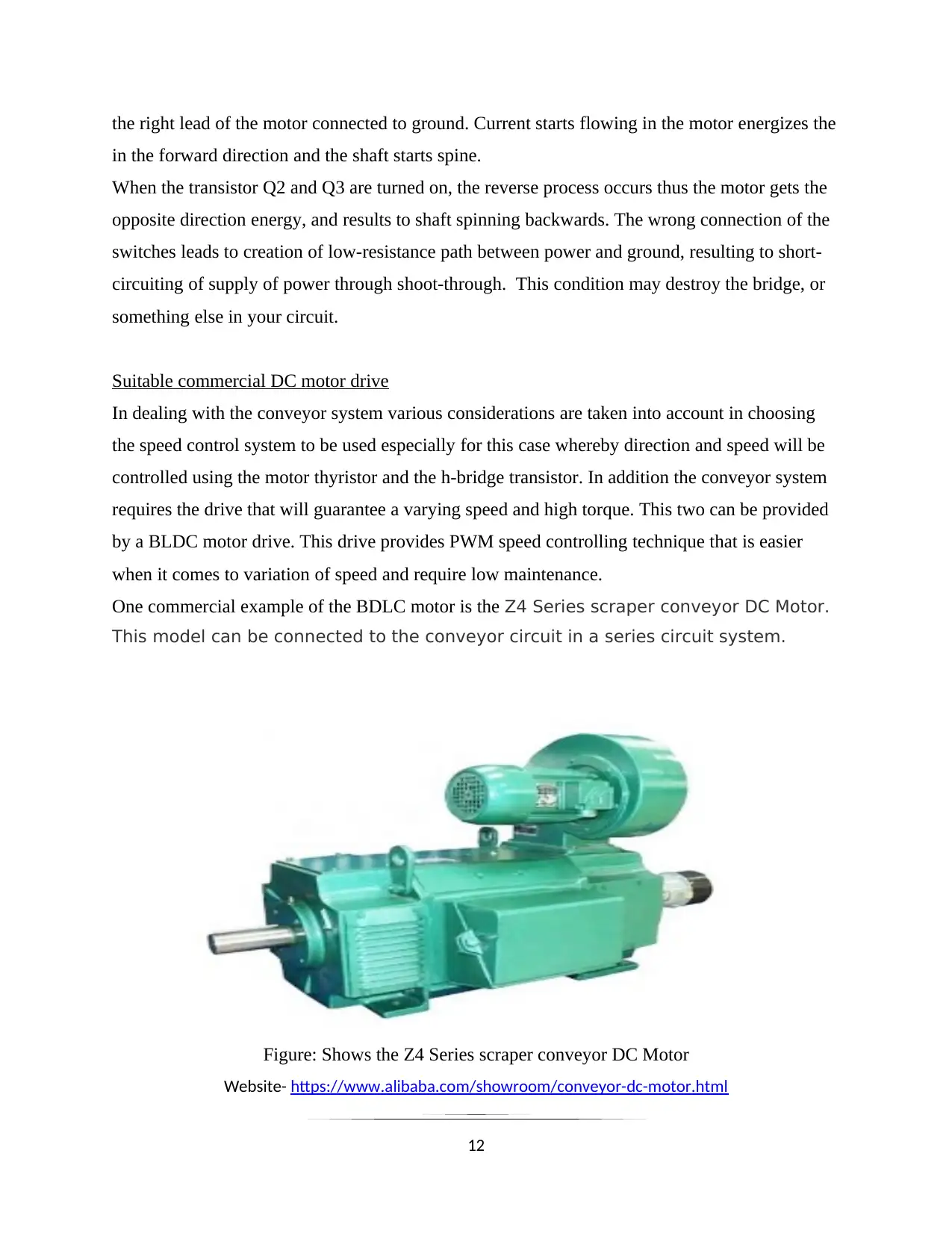
One commercial example of the BDLC motor is the Z4 Series scraper conveyor DC Motor.
This model can be connected to the conveyor circuit in a series circuit system.
Figure: Shows the Z4 Series scraper conveyor DC Motor
Website- https://www.alibaba.com/showroom/conveyor-dc-motor.html
12
in the forward direction and the shaft starts spine.
When the transistor Q2 and Q3 are turned on, the reverse process occurs thus the motor gets the
opposite direction energy, and results to shaft spinning backwards. The wrong connection of the
switches leads to creation of low-resistance path between power and ground, resulting to short-
circuiting of supply of power through shoot-through. This condition may destroy the bridge, or
something else in your circuit.
Suitable commercial DC motor drive
In dealing with the conveyor system various considerations are taken into account in choosing
the speed control system to be used especially for this case whereby direction and speed will be
controlled using the motor thyristor and the h-bridge transistor. In addition the conveyor system
requires the drive that will guarantee a varying speed and high torque. This two can be provided
by a BLDC motor drive. This drive provides PWM speed controlling technique that is easier
when it comes to variation of speed and require low maintenance.
One commercial example of the BDLC motor is the Z4 Series scraper conveyor DC Motor.
This model can be connected to the conveyor circuit in a series circuit system.
Figure: Shows the Z4 Series scraper conveyor DC Motor
Website- https://www.alibaba.com/showroom/conveyor-dc-motor.html
12
⊘ This is a preview!⊘
Do you want full access?
Subscribe today to unlock all pages.
Trusted by 1+ million students worldwide
1 out of 18
Related Documents


Your All-in-One AI-Powered Toolkit for Academic Success.
+13062052269
info@desklib.com
Available 24*7 on WhatsApp / Email
![[object Object]](/_next/static/media/star-bottom.7253800d.svg)
Unlock your academic potential
Copyright © 2020–2026 A2Z Services. All Rights Reserved. Developed and managed by ZUCOL.