Electrical Power and Machines Assignment: Power Factor and Circuits

Verified

Added on  2021/04/17

|7
|1050
|444
Report
AI Summary
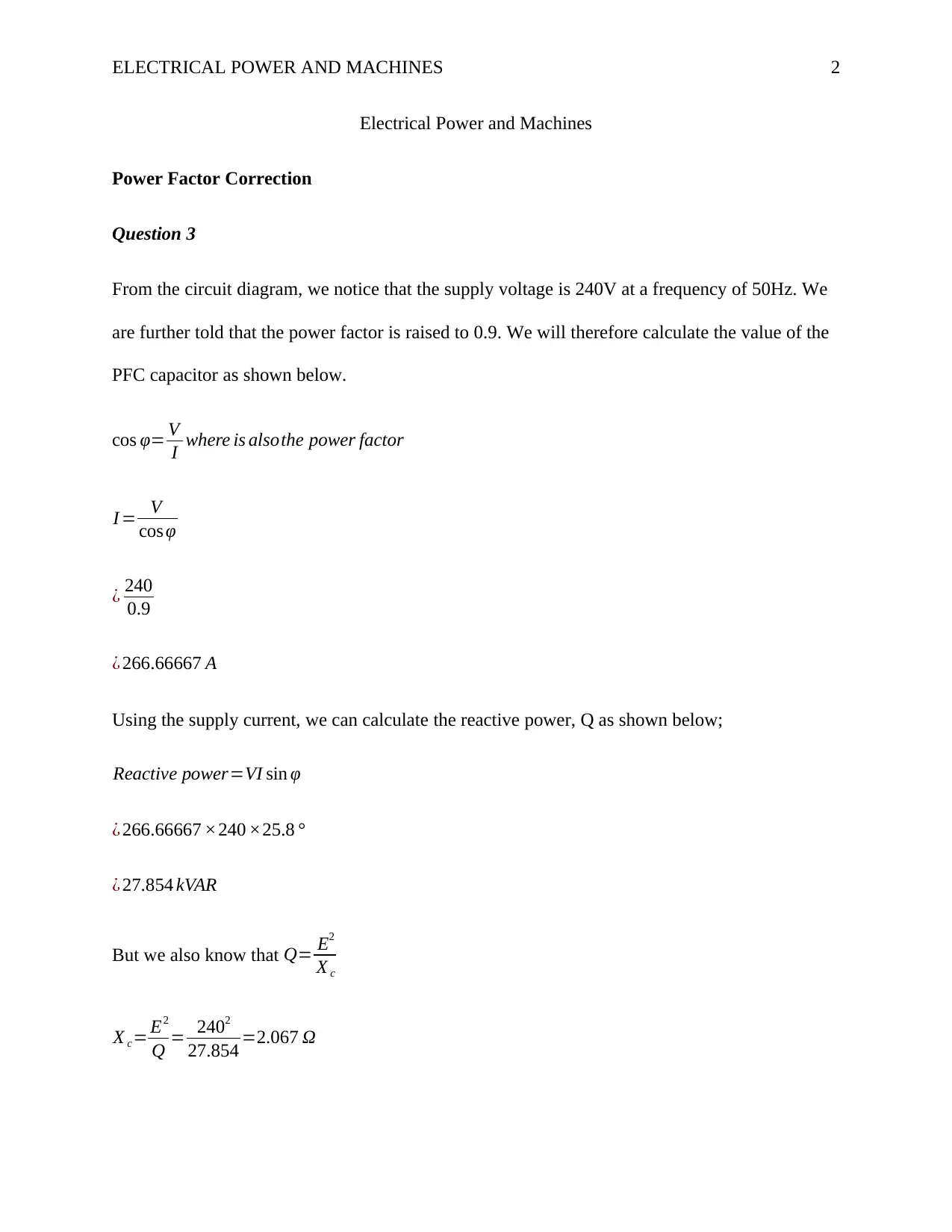
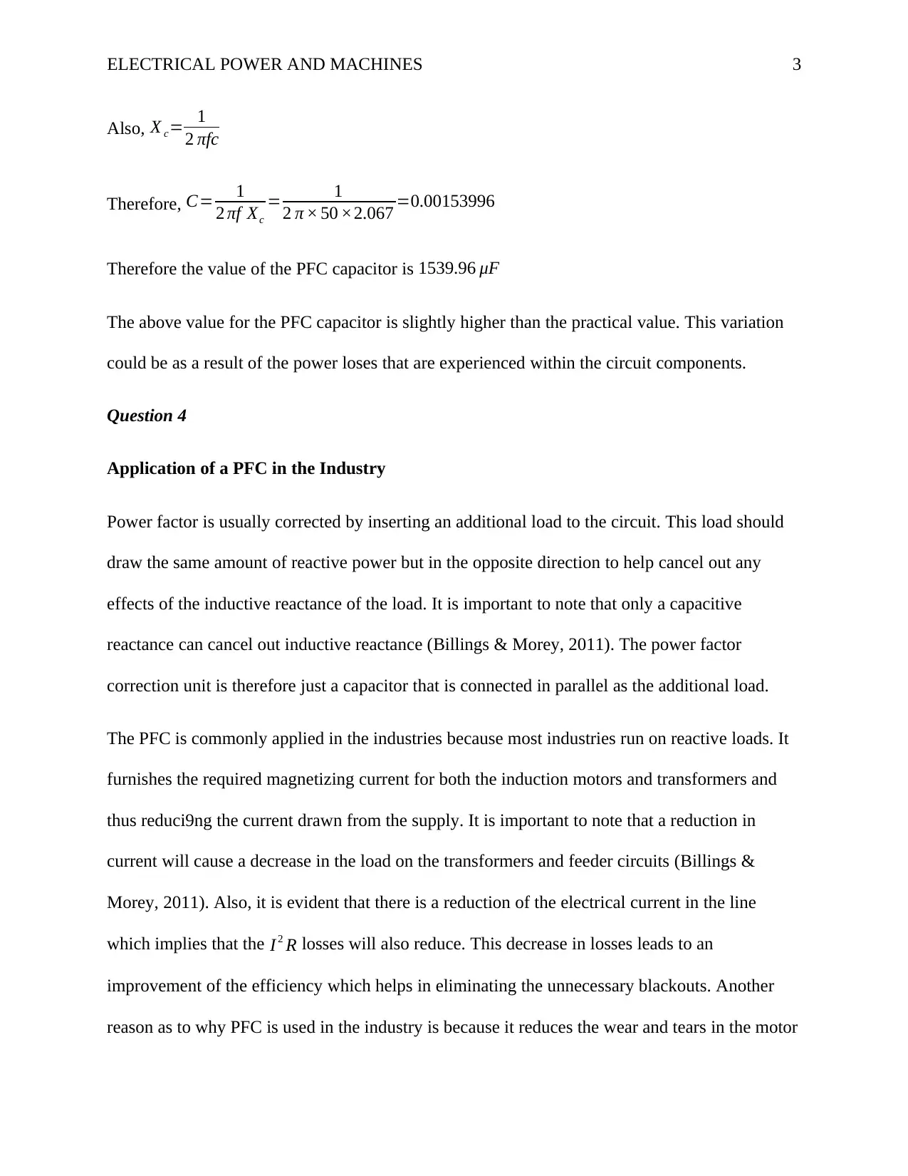
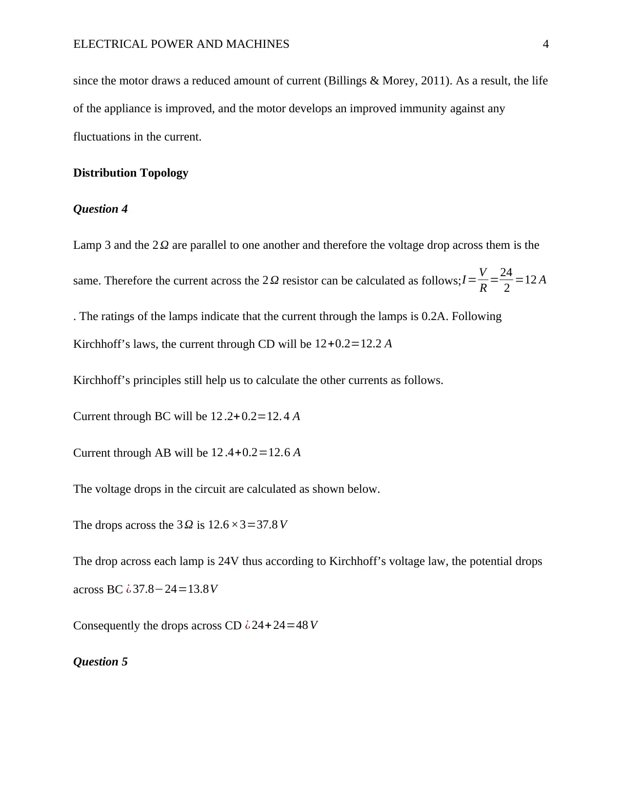
This report on Electrical Power and Machines analyzes power factor correction (PFC) techniques, including the calculation of a PFC capacitor value, considering potential variations due to circuit component losses. It explores the application of PFC in industries, highlighting its role in reducing reactive power, improving motor efficiency, and minimizing electrical losses. The report also investigates distribution topologies, specifically examining a circuit's voltage drops and current flows using Kirchhoff's laws, and compares predicted versus experimental results, addressing potential sources of error such as instrument drift and calibration issues. Finally, it presents the advantages and disadvantages of radial and ring distribution circuits, discussing factors like simplicity, maintenance costs, voltage drop, and reliability.
tabler-icon-diamond-filled.svg

Contribute Materials

Your contribution can guide someone’s learning journey. Share your documents today.
Document Page
Running head: ELECTRICAL POWER AND MACHINES
1
Electrical Power and Machines
Name
Institution
tabler-icon-diamond-filled.svg

Secure Best Marks with AI Grader

Need help grading? Try our AI Grader for instant feedback on your assignments.
Document Page
ELECTRICAL POWER AND MACHINES 2
Electrical Power and Machines
Power Factor Correction
Question 3
From the circuit diagram, we notice that the supply voltage is 240V at a frequency of 50Hz. We
are further told that the power factor is raised to 0.9. We will therefore calculate the value of the
PFC capacitor as shown below.
cos φ= V
I where is alsothe power factor
I = V
cos φ
¿ 240
0.9
¿ 266.66667 A
Using the supply current, we can calculate the reactive power, Q as shown below;
Reactive power=VI sin φ
¿ 266.66667 ×240 ×25.8 °
¿ 27.854 kVAR
But we also know that Q= E2
X c
X c= E2
Q = 2402
27.854 =2.067 Ω
Document Page
ELECTRICAL POWER AND MACHINES 3
Also, X c= 1
2 πfc
Therefore, C= 1
2 πf Xc
= 1
2 π × 50 ×2.067 =0.00153996
Therefore the value of the PFC capacitor is 1539.96 μF
The above value for the PFC capacitor is slightly higher than the practical value. This variation
could be as a result of the power loses that are experienced within the circuit components.
Question 4
Application of a PFC in the Industry
Power factor is usually corrected by inserting an additional load to the circuit. This load should
draw the same amount of reactive power but in the opposite direction to help cancel out any
effects of the inductive reactance of the load. It is important to note that only a capacitive
reactance can cancel out inductive reactance (Billings & Morey, 2011). The power factor
correction unit is therefore just a capacitor that is connected in parallel as the additional load.
The PFC is commonly applied in the industries because most industries run on reactive loads. It
furnishes the required magnetizing current for both the induction motors and transformers and
thus reduci9ng the current drawn from the supply. It is important to note that a reduction in
current will cause a decrease in the load on the transformers and feeder circuits (Billings &
Morey, 2011). Also, it is evident that there is a reduction of the electrical current in the line
which implies that the I 2 R losses will also reduce. This decrease in losses leads to an
improvement of the efficiency which helps in eliminating the unnecessary blackouts. Another
reason as to why PFC is used in the industry is because it reduces the wear and tears in the motor
Document Page
ELECTRICAL POWER AND MACHINES 4
since the motor draws a reduced amount of current (Billings & Morey, 2011). As a result, the life
of the appliance is improved, and the motor develops an improved immunity against any
fluctuations in the current.
Distribution Topology
Question 4
Lamp 3 and the 2 Ω are parallel to one another and therefore the voltage drop across them is the
same. Therefore the current across the 2 Ω resistor can be calculated as follows;I = V
R =24
2 =12 A
. The ratings of the lamps indicate that the current through the lamps is 0.2A. Following
Kirchhoff’s laws, the current through CD will be 12+0.2=12.2 A
Kirchhoff’s principles still help us to calculate the other currents as follows.
Current through BC will be 12 .2+ 0.2=12. 4 A
Current through AB will be 12 .4+0.2=12.6 A
The voltage drops in the circuit are calculated as shown below.
The drops across the 3 Ω is 12.6 ×3=37.8 V
The drop across each lamp is 24V thus according to Kirchhoff’s voltage law, the potential drops
across BC ¿ 37.824=13.8V
Consequently the drops across CD ¿ 24+ 24=48 V
Question 5
tabler-icon-diamond-filled.svg

Secure Best Marks with AI Grader

Need help grading? Try our AI Grader for instant feedback on your assignments.
Document Page
ELECTRICAL POWER AND MACHINES 5
There are differences between the predicted and the experimental results. We notice that our
experimental values are slightly lower than the predicted values. This could be caused by many
factors as outlined below.
Firstly, there could be drifts in the instruments used for measurements. It is worth noting the
readings in most electronic measuring devices always drift after some time. The amount of drift
will determine the extent of the error, and even though it is rarely significant, sometimes the drift
could just be enough to influence the reading. Another possible cause of the difference could be
due to drops along the circuit. The circuit components carry internal resistances that cause
potential to drop as current moves throughout it. Other errors and differences arise from poorly
calibrated measuring devices. Calibration is very crucial when precision and accuracy is desired.
Additionally, the difference in measurements can also result from personal errors. This could be
due to carelessness and poor technique by the individual carrying out the experiment. It is
therefore imperative to handle this experiment with the seriousness it deserves to achieve
accurate and precise results.
Question 6: Advantages and Disadvantages of Radial and Ring Circuits
The radial system of distribution has the following advantages (Brown, 2017).
i. It is a simple system of distribution since it is only fed at one end.
ii. The maintenance cost of a radial system is relatively lower when compared to the ring
circuit.
iii. It works perfectly with stations that are located centrally to the loads.
iv. The initial cost of setting up this system is relatively lower than that of the ring
topology.
Document Page
ELECTRICAL POWER AND MACHINES 6
v. The number of cables required in this system is less as compared to the other systems.
Despite all the advantages mentioned above, it is worth noting that the radial system also has its
disadvantages. These disadvantages are as listed below.
i. The end of the distributor that is close to the substation is normally very loaded.
ii. The whole of the radial system goes off in the event of a fault.
The ring system also has its advantages and disadvantages. The advantages include;
i. The power in this system is supplied from both ends.
ii. The voltage drop in a ring topology is less along the distribution line when compared to
radial system.
iii. The clients witness fewer voltage fluctuations at their terminals.
The disadvantages of this system include;
i. The cost of maintenance usually is very high.
ii. It is not applicable for clients located at the center of the load.
iii. The initial cost of a ring system is very high.
Document Page
ELECTRICAL POWER AND MACHINES 7
References
Billings, K. H., & Morey, T. (2011). Switchmode power supply handbook. McGraw-Hill.
Brown, R. E. (2017). Electric power distribution reliability. CRC press.
chevron_up_icon
1 out of 7
circle_padding
hide_on_mobile
zoom_out_icon
logo.png

Your All-in-One AI-Powered Toolkit for Academic Success.

Available 24*7 on WhatsApp / Email

[object Object]