Analysis of Electrical Power Transmission and Compensation
VerifiedAdded on 2023/03/20
|36
|5270
|76
Report
AI Summary
This report delves into the intricacies of electrical power transmission and compensation, exploring various methods to optimize power delivery and maintain system stability. The report examines the use of shunt capacitors for voltage compensation, analyzing their impact on reactive power and power flow within the transmission line. It further investigates the application of STATCOM (Static Synchronous Compensator) and autotransformers for voltage regulation and reactive power management, providing detailed insights into their operational principles and effectiveness. The analysis includes the impact of phase shifts, inductive reactance, and load variations on power transfer, offering a comprehensive understanding of the factors influencing the efficiency and stability of electrical power systems. The report also covers the characteristics of synchronous machines and the design considerations for high-voltage direct current (HVDC) systems in power transmission. Simulation results and experimental observations are presented to validate the theoretical concepts and demonstrate the practical application of these compensation techniques. The report concludes with a discussion on the scopes of the simulation and how compensation varies the voltage through the STATCOM unit.

Electrical power 1
ELECTRICAL POWER
Authors Name/s per 1st Affiliation (Author)
Dept. name of the organization
Name of organization, acronyms acceptable
City, Country
mail address
Authors Name/s per 2nd Affiliation (Author)
Dept. name of the organization
Name of organization, acronyms acceptable
City, Country
e-mail address
Paraphrase This Document
Need a fresh take? Get an instant paraphrase of this document with our AI Paraphraser
Electrical Power 2
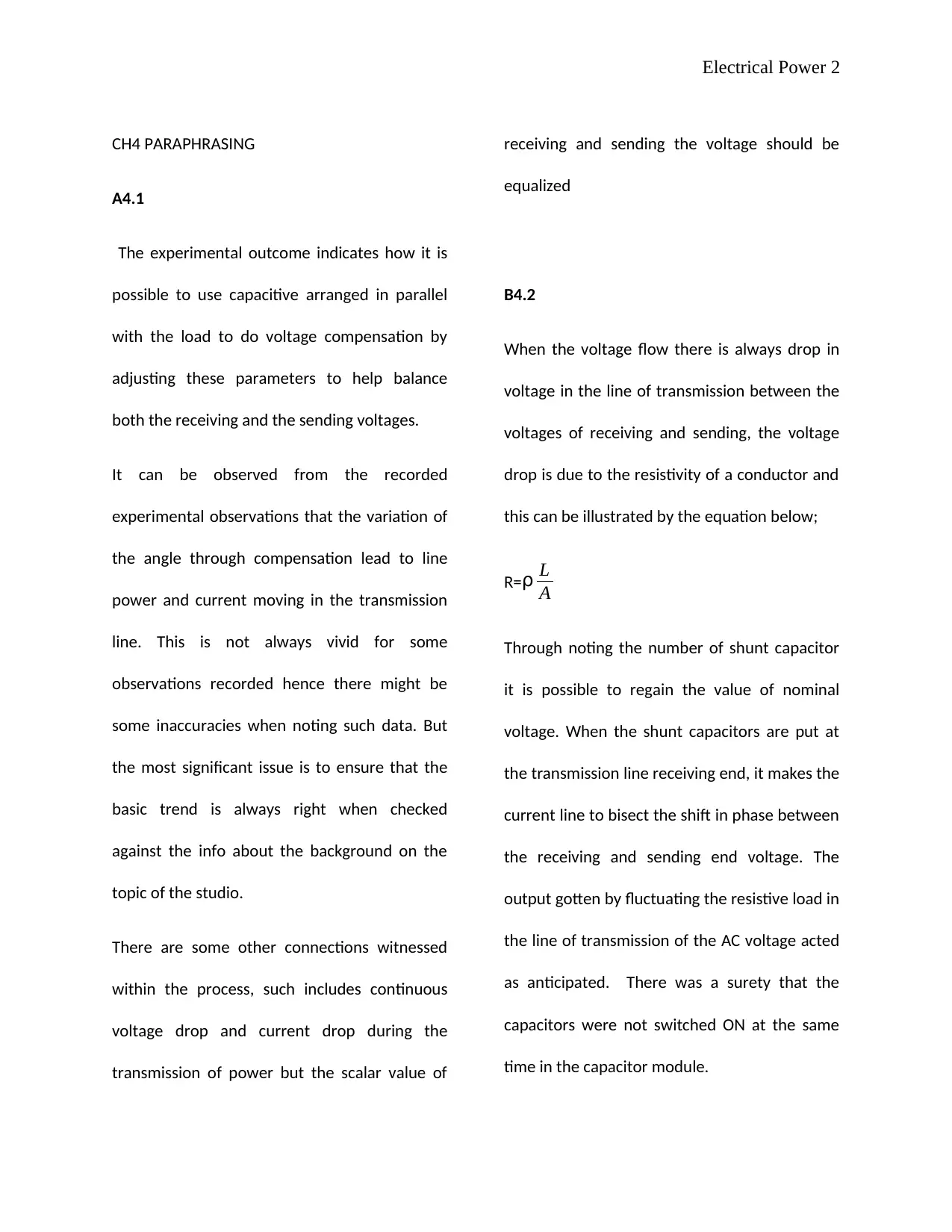
CH4 PARAPHRASING
A4.1
The experimental outcome indicates how it is
possible to use capacitive arranged in parallel
with the load to do voltage compensation by
adjusting these parameters to help balance
both the receiving and the sending voltages.
It can be observed from the recorded
experimental observations that the variation of
the angle through compensation lead to line
power and current moving in the transmission
line. This is not always vivid for some
observations recorded hence there might be
some inaccuracies when noting such data. But
the most significant issue is to ensure that the
basic trend is always right when checked
against the info about the background on the
topic of the studio.
There are some other connections witnessed
within the process, such includes continuous
voltage drop and current drop during the
transmission of power but the scalar value of
receiving and sending the voltage should be
equalized
B4.2
When the voltage flow there is always drop in
voltage in the line of transmission between the
voltages of receiving and sending, the voltage
drop is due to the resistivity of a conductor and
this can be illustrated by the equation below;
R=⍴ L
A
Through noting the number of shunt capacitor
it is possible to regain the value of nominal
voltage. When the shunt capacitors are put at
the transmission line receiving end, it makes the
current line to bisect the shift in phase between
the receiving and sending end voltage. The
output gotten by fluctuating the resistive load in
the line of transmission of the AC voltage acted
as anticipated. There was a surety that the
capacitors were not switched ON at the same
time in the capacitor module.
Electrical Power 3
Since the nominal voltage needs to be
maintained, at the receiving end there were
some capacitors which were employed to
realize this by increasing the receiving end
voltage. There may be a serious fault in the
gadgets of the line of transmission in case the
loads in the line of transmission are completely
removed from the line. There was a surety that
the capacitors were switched ON at different
times.
B4.2.1
The drop in voltage at the transmission line
receiving end was as expected when there were
no capacitors. The drop in voltage was
witnessed again where the shunt capacitors
were introduced, the network for power was as
well balanced [1]. With this simulation was
completed effectively.
A5.1
After concluding for the transmission line
capacity of the power transmission some of the
things were seen and deduced. Some of these
include; when in need for the active power to
move from the receiving end of the
transmission end, the shift in phase has to exist
in the voltage. In case the sending and receiving
voltage´s sine wave are in phase the
instantaneous voltage value at the receiving
and sending end will be at all times be equal
hence the active power will never flow.
During the experiment, it was seen that
transferred active power through transmission
line are the shift in phase between the receiving
and sending ends will increase until the
maximum value is attained when the shift is
equal to 900 . Nevertheless, optimizing
transferred output power through the voltage
AC voltage compensation in the transmission
line. This is attained by adjusting the shift in
phase until it reaches 900. This phase shift can
produce some unstable system since at this
point voltage cannot be compensated further.
⊘ This is a preview!⊘
Do you want full access?
Subscribe today to unlock all pages.

Trusted by 1+ million students worldwide
Electrical Power 4
Therefore it is significant to make sure that the
system of transmission will give the demanded
active power at the same time ensuring that
shift between the receiving and sending end is
much below 900 and in most scenarios, it is 300
The study in this assignment has deduced that
the reactance due to the inductors in a line of
transmission is inversely proportional to the
flow of real power but directly proportional to
the transmission line length [2]. Therefore the
real power optimum flow in the transmission
line, reactance due to inductor and length for
every conductor kilometre have to be
maintained as minimum as possible. This is a
perfect way of real power flow capacity
maximization as well as making sure that the
system keeps to the optimal stability.
A5.1.2
The outcomes from the MATLAB simulation
indicates that a roughly equal real power was
transferred in the AC transmission
compensated system. This was done at a reduce
phase shift in receiving and sending end
voltages and at that point reactance due to
inductors were decreased.
The simulations outcomes then help in doing
the verifications of the practical finding activity.
It was seen during the experiment that for
compensated voltage system, through
decreasing the reactance due to the inductor in
the transmission line, there will be an equal
level of real power in the reduced shift in phase
between the receiving and the sending end
voltage. This has advantages since it reduces
the reactance due to inductance in the line of
transmission [3].
B5.2
For this experiment capacitive load was
connected first then inductive load as well as
resistive load was connected to the system to
help analyse the drop in voltage and also phase
angles in the compensated line. In case the
Paraphrase This Document
Need a fresh take? Get an instant paraphrase of this document with our AI Paraphraser
Electrical Power 5
shunt capacitive load is used in the connection
then the outcome was that receiving voltage
was lagged by sending voltage. This implies that
the voltage receiving end was much less due to
the absorption voltage from the inductance.
But if we connect a load which is restive the
result gave no lag or lead-in phase. Hence the
sending end voltage is roughly equal to the
voltage at the receiving end. It can hence be
concluded that adding these shunt capacitors is
an appropriate way to give the optimum
reactive power in the transmission line [4].
A6.1
From the experiment done there was a vivid
indication that autotransformers can be
employed for adjusting the receiving and
sending voltage phase angles to help in power
flow regulations in two transmission lines. This
is realized in either direction so long as the
power level transmitted and relative phase
angles are involved.
B6.2
In case the receiver and sender voltage are in
phase to one another in the AC line of
transmission, then the real power is transmitted
through the reactive and line power is given in
similar quantity to the line of receiving and
sending voltage ends. The more the angle of
phase shifts the more the reactive power
engrossed by the transmission line
When the shift fluctuates to 150 and -150, the
real flow of power direction is altered. There
were no modifications of voltage hence it was
seen that there existed no flow of power in the
AC line when the power shift was 0. Hence to
ensure that for the transferred power in more
areas it is needed that they must have a phase
shift to help share the electrical power [5].
If we use an autotransformer is employed as a
step up transformers, it has the ability to reduce
or increase reactive power through the
Electrical Power 6
incoming phase shift voltages. The anticipated
values of decreased and increased voltage are
met through employing several taps on the
windings of the transformer and this is with
accordance with turn’s ratio.
A7.1
In the whole session of the practical, the
working and employment of a STATCOM to help
compensate voltage in transmission line was
illustrated and thoroughly scrutinized.
If the STATCOM was put in the transmission
line´s receiving end resistive load resistance was
confirmed and the correct information was
noted down. This indicates that a STATCOM
could be quickly and precisely compensate and
respond to the system through feeding required
amount of reactive power to make sure that the
voltage at the receiver end is almost the same
as that at the sender end [6].
The compensation speed was seen to be
between the two and one cycles of the sine
wave that is roughly instantaneous. This is a big
quality to efficiency of STATCOM compensation
voltage.
When the STATCOM I put at the receiver end
still of the line of transmission, therefore in the
middle of the line shunt capacitor was put.
During the experiment, it was clear that when
the shunt capacitor was included in AC line of
transmission, there was no consequence on the
appropriate compensation system of the
STATCOM.
In summary, it was approved that
compensating reactive power was very
operative when STSTCOM was used in the
whole transmission line [7].
A8.1
There are scopes which follow these activity´s
description of the simulation and illustrate the
variation in the power and how the
⊘ This is a preview!⊘
Do you want full access?
Subscribe today to unlock all pages.

Trusted by 1+ million students worldwide
Electrical Power 7
compensation varies the voltage through the
STATCOM unit.
The first scope illustrates the early process of
stabilization process which is followed by some
variations where there is the production of
current and amendment to do the
compensation of the voltage.
The second scope illustrates variations and also
0.2 where there some current drop to surge and
negative in the reactive power which is then
compensated to 0.3 for this process till the
nominal value of the voltage moves to 0.4.
And in the third scop it illustrates the process at
0.2 where there are trivial power changes on
the 1 st records then the prominent act of the
STATCOM in the process since there is a rise in
current and voltage waveform in the final
readings in the scope.
A8.1.2
“Data Acquisition station 1:”
Since the real power is often checked in the
trace illustrates that it increasing from zero to 1
pu it again reduces to about 1.5 s when the
power reduces to 0.95 pu.
The real power illustrates an initially jumped
market as ramp up system which is followed by
a marked variation at 1.5 s in which the reactive
power reduces hence it will be correct the
system for the system reactive capacitance. It
was then witnessed that the system was stable
there was more system with a few small
variations was enacted [8].
“Data Acquisition station 2:”
On the trace two direct current voltages after
the initial stabilization rests at about 1pu till it
reaches 1.5s and this goes on till there is
variation where there are voltage drop and
oscillation for the same period. Therefore at 2.5
s, it will drop gradually again because of the
Paraphrase This Document
Need a fresh take? Get an instant paraphrase of this document with our AI Paraphraser
Electrical Power 8
fluctuations but this elections must be close to
1pu which is a reference point.
A8.1.3
The simulation is done on these three gadgets
allows giving an illustration on how the
operating in regulating current, voltage,
reactive and real power in the transmission line.
The SVS and STATCOM system are perfectly
simulated to illustrate how the compensation
for the load variation and decrease or increases
in the systems reactive power to make the
stable power remain stable in the network [9].
The system of HVDC must deal with variations
as it transfers it in direct current form again
when it is reversed back to thigh AC voltage to
be used in power grid. The design illustrated the
voltage compensation to keep the transmission
in the needed pu parameters.
Electrical Power 9
ARTICLE 1
Synchronous machine
While in steady state, the rotation of a
synchronous machine is at a constant speed.
Direct current (ac) excitation is provided to the
field that winds to the rotor whereas the
alternating current is supplied in the armature
winding. Synchronous machines can use either
a motor or a generator.
Constructional features
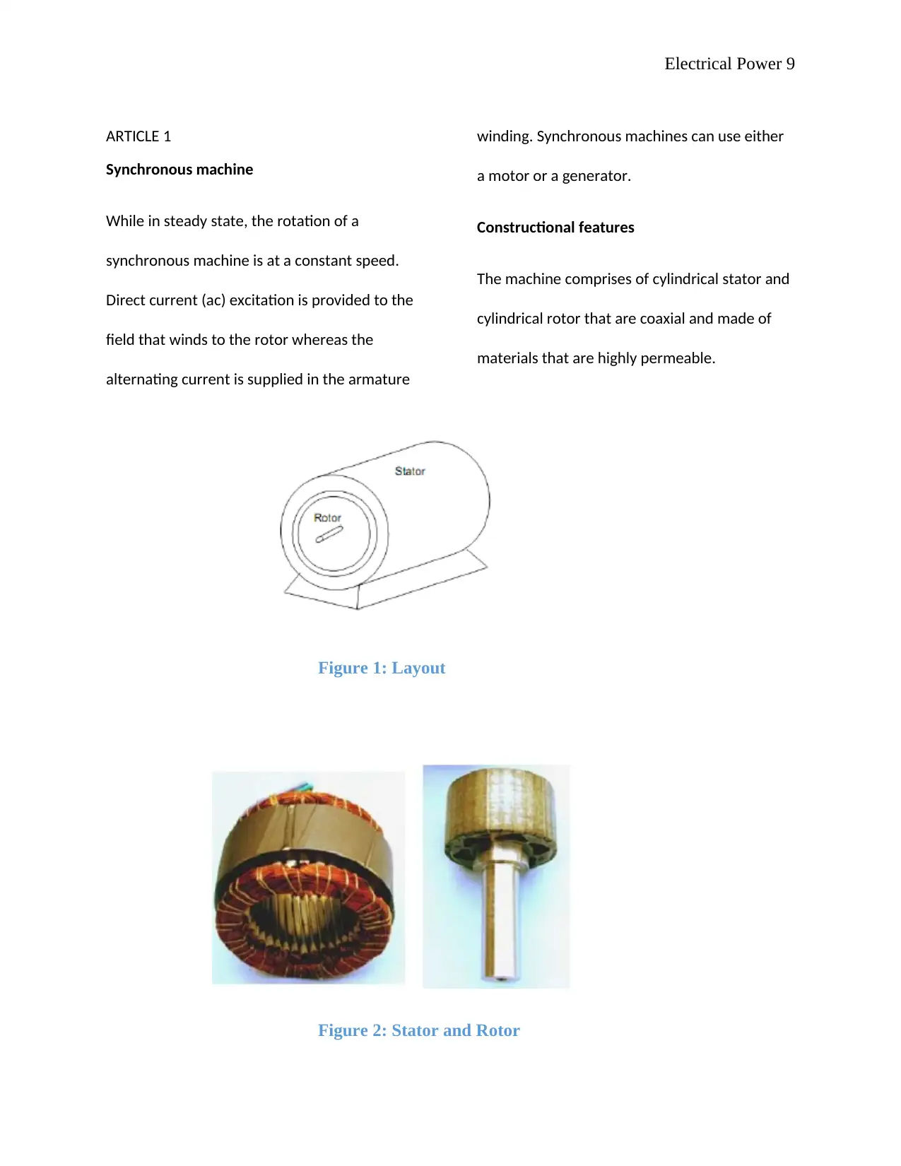
The machine comprises of cylindrical stator and
cylindrical rotor that are coaxial and made of
materials that are highly permeable.
Figure 1: Layout
Figure 2: Stator and Rotor
⊘ This is a preview!⊘
Do you want full access?
Subscribe today to unlock all pages.

Trusted by 1+ million students worldwide
Electrical Power 10
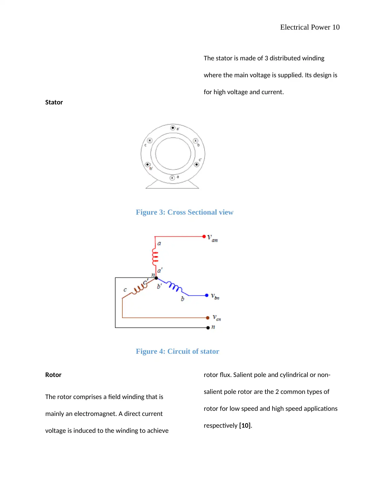
Stator
The stator is made of 3 distributed winding
where the main voltage is supplied. Its design is
for high voltage and current.
Figure 3: Cross Sectional view
Figure 4: Circuit of stator
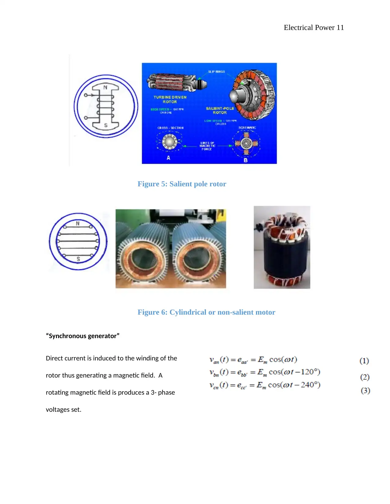
Rotor
The rotor comprises a field winding that is
mainly an electromagnet. A direct current
voltage is induced to the winding to achieve
rotor flux. Salient pole and cylindrical or non-
salient pole rotor are the 2 common types of
rotor for low speed and high speed applications
respectively [10].
Paraphrase This Document
Need a fresh take? Get an instant paraphrase of this document with our AI Paraphraser
Electrical Power 11
Figure 5: Salient pole rotor
Figure 6: Cylindrical or non-salient motor
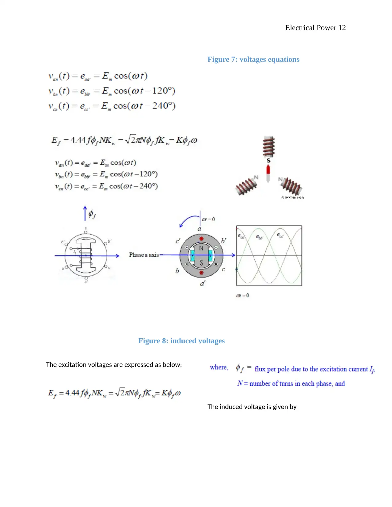
“Synchronous generator”
Direct current is induced to the winding of the
rotor thus generating a magnetic field. A
rotating magnetic field is produces a 3- phase
voltages set.
Figure 5: Salient pole rotor
Figure 6: Cylindrical or non-salient motor
“Synchronous generator”
Direct current is induced to the winding of the
rotor thus generating a magnetic field. A
rotating magnetic field is produces a 3- phase
voltages set.
Electrical Power 12
Figure 7: voltages equations
Figure 8: induced voltages
The excitation voltages are expressed as below;
The induced voltage is given by
Figure 7: voltages equations
Figure 8: induced voltages
The excitation voltages are expressed as below;
The induced voltage is given by
⊘ This is a preview!⊘
Do you want full access?
Subscribe today to unlock all pages.

Trusted by 1+ million students worldwide
1 out of 36
Related Documents
Your All-in-One AI-Powered Toolkit for Academic Success.
+13062052269
info@desklib.com
Available 24*7 on WhatsApp / Email
![[object Object]](/_next/static/media/star-bottom.7253800d.svg)
Unlock your academic potential
Copyright © 2020–2026 A2Z Services. All Rights Reserved. Developed and managed by ZUCOL.


