Experiment Report: Analysis of RLC Circuits Reactants and Impedance

Verified

Added on  2023/01/04

|9
|1683
|77
Report
AI Summary
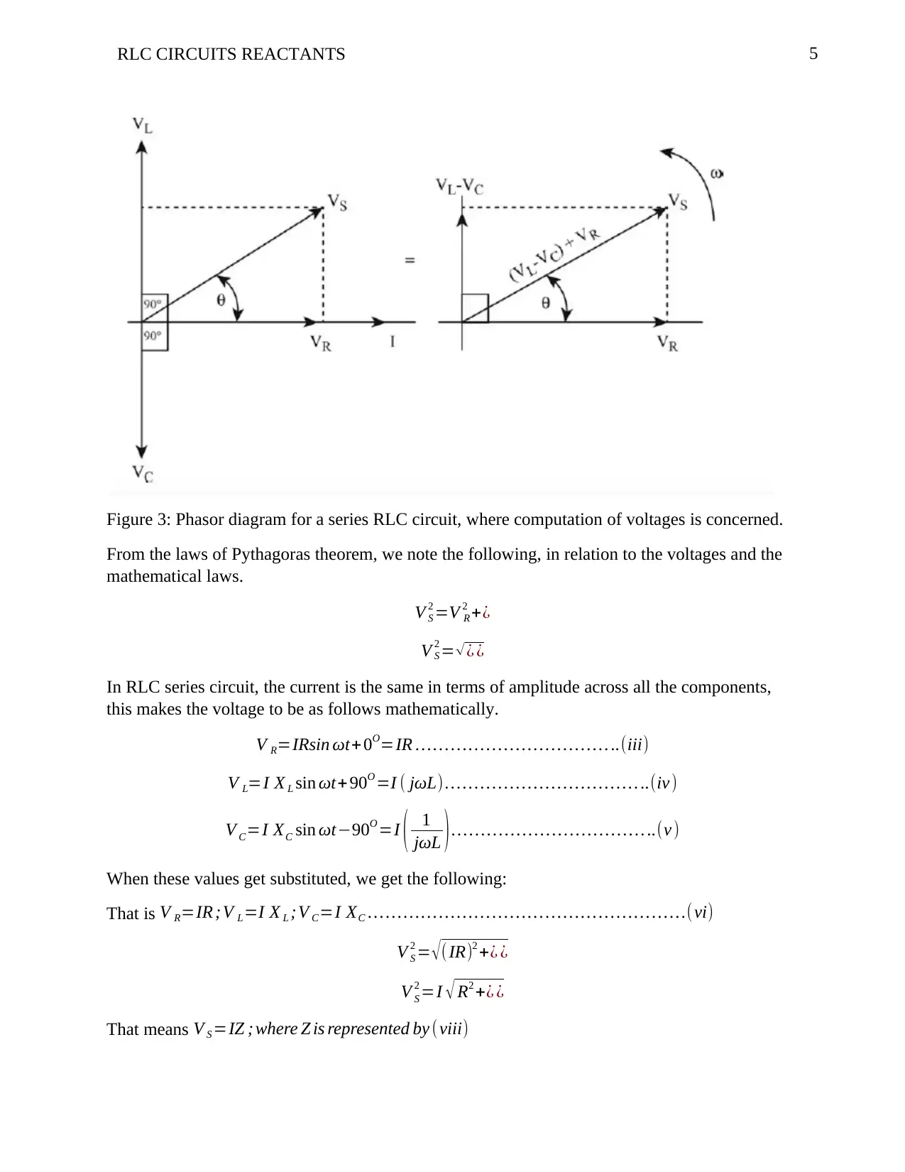
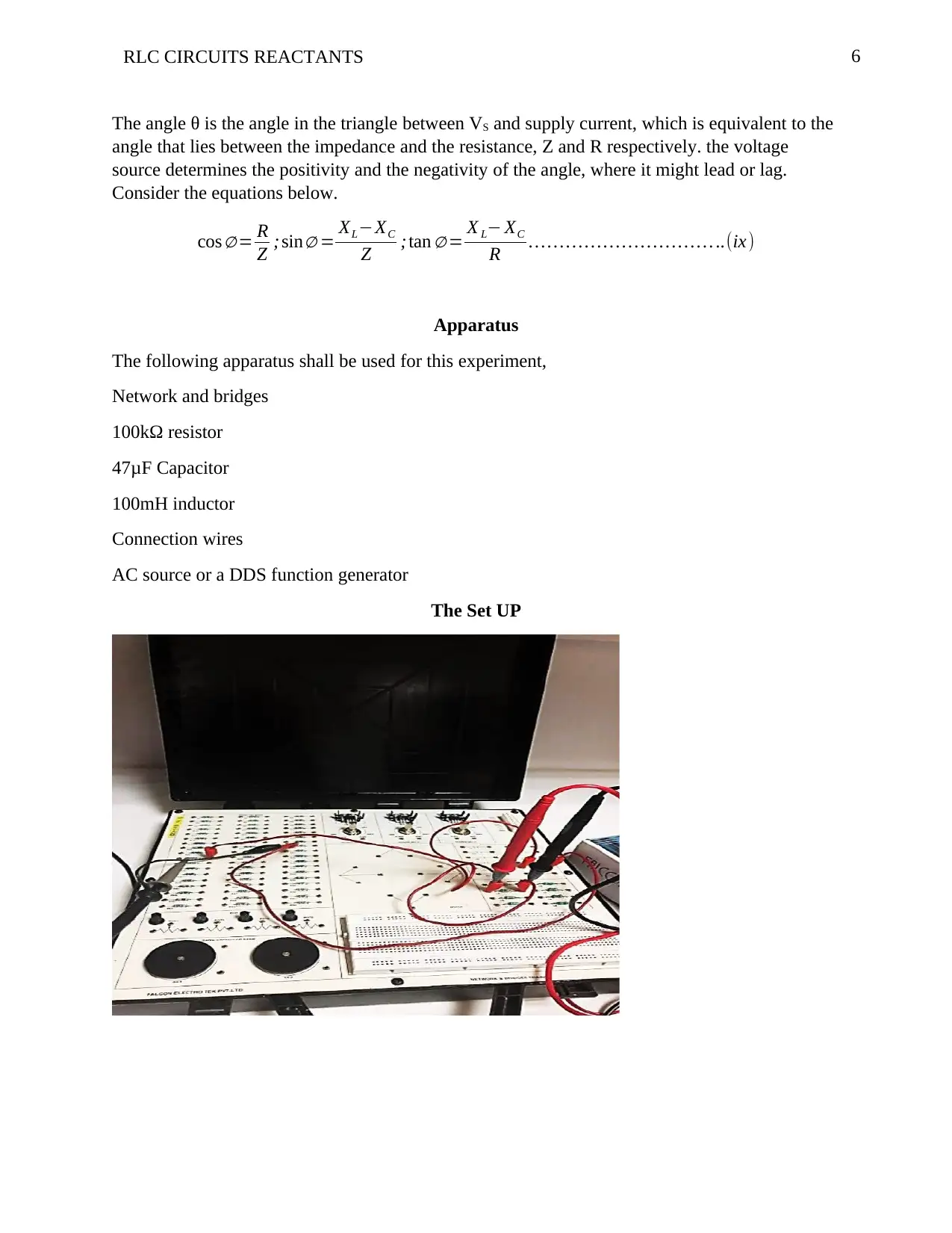
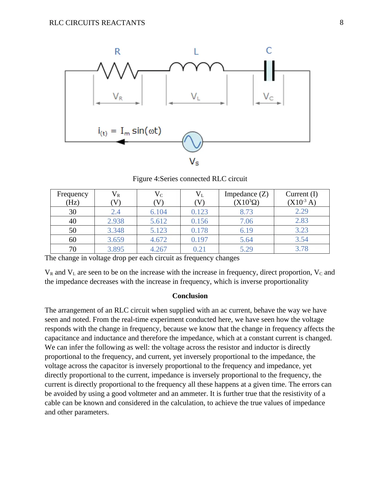
This report details an experiment on RLC circuits, focusing on the behavior of resistors, inductors, and capacitors in series and parallel configurations when subjected to an alternating current. The report begins with an introduction to the components and their phase relationships, followed by a theoretical overview of reactance and impedance. It then delves into the analysis of series RLC circuits, providing equations for inductive reactance, capacitive reactance, and impedance. The experimental setup, including the apparatus used and the procedure followed, is described. The results section presents both theoretical calculations and measured values for voltages across the components at varying frequencies, along with observations and analysis of the data. The report concludes with an interpretation of the results, highlighting the relationships between frequency, voltage, current, and impedance, and suggesting potential sources of error and improvements. The report emphasizes the direct and inverse proportionality of voltage, current, and impedance with frequency, and their impact on circuit behavior. The report is a valuable resource for students studying electrical engineering, providing insights into the practical application of RLC circuits and their underlying principles.
Document Page
1Running head: RLC CIRCUITS REACTANTS
RLC CIRCUITS REACTANTS
Name
Institutional Affiliation
tabler-icon-diamond-filled.svg

Secure Best Marks with AI Grader

Need help grading? Try our AI Grader for instant feedback on your assignments.
Document Page
2RLC CIRCUITS REACTANTS
RLC CIRCUITS REACTANTS
Introduction
This experiment aims at familiarity with the components mentioned and how they
behave in a circuit when put together, either parallel or connected in series, and the circuit fed by
an alternating current.
Theory
The three basic passive components that are of focus are the resistance, inductance,
and capacitance which have distinct phase relationships among themselves when the circuitry is
of alternating supply that is sinusoidal in nature. When the resistor is alone in the circuit, the
waveform shall be in-phase with the current. When there is only an inductor the voltage wave
form is leading the current by 90O. When the circuit contain only capacitance, the wave
representing voltage shall be lagging the current by 90O. The reactive value produced by the
components mentioned above is what gives the phase differences. When the circuit is purely
resistive, only has resistance, the reactance is zero, it will be negative when the circuit is
capacitive and positive then the circuit is purely inductive. The table below shows a relationship
of the RLC circuit as described, only that this time there shall the impedance, which the table
shows how it relates to the other components as well (talked about in the next section)
Component
Resisto
r (R)
Reactance
(X)
Impedance
(Z)
Resistor R 0 Z=R =R<0
Inductor 0 ωL
ZL = jωL =
ωL<+90
Capacitor 0 1/ωC
ZC=1/jωC
=1/ωC<-90
The impedance of the components
The three elements can be combined together and analysed, where they can be connected in
series or parallel, to form an RLC circuit. When analysing the RLC circuit, we shall need to take
into consideration the inductive, capacitive reactance and the resistances, XL, XC, and R
respectively. This will enable us to obtain the reactance of the circuit. Series RLC circuit are in a
class of 2nd order circuits since they store energy in two elements which are the capacitance and
inductance, see figure 1.
Document Page
3RLC CIRCUITS REACTANTS
Figure 1: RLC circuit connected in series
There only one loop in the circuit of instantaneous current that flows through the loop, that
means the current flowing is the same for every component of the circuit. The inductive and
capacitive reactance of the circuit depends on the frequency at the supply, therefore the response
happening in sinusoidal way varies with the frequency. The voltage drops across individual each
element will be out of phase with one another.
i(t )=Imax sin ( ωt ) ..(1)
Voltage across the resistor is written as VR shall be in phase with the current
Voltage across the inductor or inductive load, VL will be leading the current by 90O
The voltage across the capacitor or capacitive load shall lag the current by 90O
We can infer that VL and VC are 180O out of phase and opposite each other.
Figure 2:Circuits showing the waveforms and the circuit and how they relate
Considering all the parameters in place and considering the circuit given therein, we can have the
following equations:
For inductive reactance we have: X L=2 πfL=ωL
Document Page
4RLC CIRCUITS REACTANTS
Reactance of the capacitor is given by: XC = 1
2 πfC = 1
ωC
If X L> XC it is an inductive circuit
If XC > XL it becomes a capacitive circuit
Reactance total for the circuit ¿ XC X L XLXC
Impedance total for the circuit shall be Z= R2+ XT
2 =R+ jX
The above equation of the inductive reactance, has a condition that if the inductance or frequency
is made big then the value of the inductance reactance will increase. The inductive reactance
against frequency phasor diagram is shown below, which is a linear curve and direct
proportionality. On the other hand, the frequency of the capacitive loads and the reactance are
inversely proportional.
Consider the following phasor diagrams that relates with the voltages across the components of
the RLC series circuit.
tabler-icon-diamond-filled.svg

Secure Best Marks with AI Grader

Need help grading? Try our AI Grader for instant feedback on your assignments.
Document Page
5RLC CIRCUITS REACTANTS
Figure 3: Phasor diagram for a series RLC circuit, where computation of voltages is concerned.
From the laws of Pythagoras theorem, we note the following, in relation to the voltages and the
mathematical laws.
V S
2 =V R
2 +¿
V S
2 = ¿ ¿
In RLC series circuit, the current is the same in terms of amplitude across all the components,
this makes the voltage to be as follows mathematically.
V R=IRsin ωt+ 0O=IR ..(iii)
V L=I X L sin ωt+ 90O =I ( jωL) ..(iv)
V C=I XC sin ωt90O =I ( 1
jωL ) ..(v )
When these values get substituted, we get the following:
That is V R=IR ;V L=I X L ; V C=I XC (vi)
V S
2 = ( IR)2 +¿ ¿
V S
2 =I R2 +¿ ¿
That means V S =IZ ; where Z is represented by (viii)
Document Page
6RLC CIRCUITS REACTANTS
The angle θ is the angle in the triangle between VS and supply current, which is equivalent to the
angle that lies between the impedance and the resistance, Z and R respectively. the voltage
source determines the positivity and the negativity of the angle, where it might lead or lag.
Consider the equations below.
cos = R
Z ; sin = XLXC
Z ;tan = X L XC
R ..(ix)
Apparatus
The following apparatus shall be used for this experiment,
Network and bridges
100kΩ resistor
47μF Capacitor
100mH inductor
Connection wires
AC source or a DDS function generator
The Set UP
Document Page
7RLC CIRCUITS REACTANTS
Results and analysis
Procedure
Theoretical Part
Here, the calculations were done to determine the values and compared to the measured values at
50Hz frequency and recorded at the “measured values” section. Calculations, shown below, were
done using the formulas (iii), (v), and (iv), and answers obtained were shown in the “Calculated
values” part. Taking current =3.23mA, frequency =50Hz, Resistor=100K, Capacitor=47μF, and
Inductor=100mH
V R=IRsin ωt+ 0O= ( 3.23 X 10³ ) ( 1000 ) =3.23 V
V C=I XC sin ωt90O =( 1
jωL )=
( 3.23 X 10³
2 πX 50 X 47 X 106 )=0.218V
V L=I X L sin ωt+ 90O =I ( jωL )=0.00323 X 2 πX 50 X 0.1=0.101V
Voltages across
components
Measured
values (V)
Calculated
values (V)
Observation
VR 3.348 3.23 Small difference observed
VC 5.123 0.218 Big difference observed
VL 0.178 0.101 Small difference observed
The circuit was formed by connecting the wires on the board to form the circuit below.
The AC source is set and voltages of VR, VC and VL then we can compare these values with the
theoretical values. Take the readings and fill the table below; the AC source varies from 30Hz to
70Hz and an interval of 10Hz
tabler-icon-diamond-filled.svg

Paraphrase This Document

Need a fresh take? Get an instant paraphrase of this document with our AI Paraphraser
Document Page
8RLC CIRCUITS REACTANTS
Figure 4:Series connected RLC circuit
Frequency
(Hz)
VR
(V)
VC
(V)
VL
(V)
Impedance (Z)
(X103Ω)
Current (I)
(X10-3 A)
30 2.4 6.104 0.123 8.73 2.29
40 2.938 5.612 0.156 7.06 2.83
50 3.348 5.123 0.178 6.19 3.23
60 3.659 4.672 0.197 5.64 3.54
70 3.895 4.267 0.21 5.29 3.78
The change in voltage drop per each circuit as frequency changes
VR and VL are seen to be on the increase with the increase in frequency, direct proportion, VC and
the impedance decreases with the increase in frequency, which is inverse proportionality
Conclusion
The arrangement of an RLC circuit when supplied with an ac current, behave the way we have
seen and noted. From the real-time experiment conducted here, we have seen how the voltage
responds with the change in frequency, because we know that the change in frequency affects the
capacitance and inductance and therefore the impedance, which at a constant current is changed.
We can infer the following as well: the voltage across the resistor and inductor is directly
proportional to the frequency, and current, yet inversely proportional to the impedance, the
voltage across the capacitor is inversely proportional to the frequency and impedance, yet
directly proportional to the current, impedance is inversely proportional to the frequency, the
current is directly proportional to the frequency all these happens at a given time. The errors can
be avoided by using a good voltmeter and an ammeter. It is further true that the resistivity of a
cable can be known and considered in the calculation, to achieve the true values of impedance
and other parameters.
Document Page
9RLC CIRCUITS REACTANTS
chevron_up_icon
1 out of 9
circle_padding
hide_on_mobile
zoom_out_icon
logo.png

Your All-in-One AI-Powered Toolkit for Academic Success.

Available 24*7 on WhatsApp / Email

[object Object]