Technical Report for Pneumatic System Experiment: Circuit Analysis
VerifiedAdded on 2022/08/25
|14
|3052
|31
Report
AI Summary
This technical report analyzes pneumatic systems, focusing on circuit diagrams and fluid dynamics. The report begins with an introduction to pneumatic systems and their design, emphasizing the use of circuit diagrams for visualizing functionality. It compares single-acting and double-acting cylinders, highlighting differences in valve configurations and fluid control. The report further explores the working fluids in circuit systems, contrasting hydraulic fluid and compressed air. The report also includes a description of the control of casting ladle circuit, the laboratory setup of pneumatic equipment, advantages and disadvantages of chosen fluids, a working model of the pneumatic circuit, assumptions made, annotated photographs, and circuit diagrams. Safety precautions are also discussed, emphasizing the proper handling of equipment and fluids. This report provides a comprehensive understanding of pneumatic systems, their components, and their applications.
TECHNICAL REPORT FOR PNEUMATIC SYSTEM EXPERIMENT1
TECHNICAL REPORT FOR PNEUMATIC SYSTEM EXPERIMENT
Course
Professor’s Name
Institution
Location of Institution
Date
TECHNICAL REPORT FOR PNEUMATIC SYSTEM EXPERIMENT
Course
Professor’s Name
Institution
Location of Institution
Date
Paraphrase This Document
Need a fresh take? Get an instant paraphrase of this document with our AI Paraphraser
TECHNICAL REPORT FOR PNEUMATIC SYSTEM EXPERIMENT2
Introduction
The design used in manufacturing pneumatic systems varies depending on where it will be used
for work. The systems are designed through circuit diagrams to give a clear picture of how they
function. Different components are being used to make a circuit, and they include; cylinders,
control valves, directional valves, signals that generate elements for initiating the process such as
shuttle and two pressure valves (McCloy and Martin, 2015). The circuits in the system control
the entry and exit of air compressed in the cylinders. They are also designed in a way that one
valve is used to control another and also to control the actuators (Frank and Stabenow, 2018).
Therefore, in this report, we are going to analyze pneumatic systems and their circuits,
depending on the purpose they are designed for.
Comparisons of application circuit diagrams
In Annex A circuit diagram for stamping, it is the cylinder. It is controlled directly by the
actuator through the directional control valve. In this design of a single-acting cylinder of the
stamping facility, the valves are made in either to be controlled electrically or manually (McCloy
and Martin, 2015). Unlike the other circuit diagram for the securement device, the circuit in the
single-acting cylinder is favorable enough to operate at low speeds. In the single-acting cylinder,
when the valve for directional control is actuated through the push button, the other valves
switch to opening another position to initiate the source for the work through the cylinder
volume. Thus, forward motion for the piston occurs. The valve closes when the push button gets
released since the spring in the cylinder, restores the valve to it is current position (Krivts and
Krejnin, 2016). This applies to a single-acting cylinder.
TECHNICAL REPORT FOR PNEUMATIC SYSTEM EXPERIMENT3
The big difference between the circuit systems of pneumatics is that the double-acting cylinder is
designed to use 5/2 for the directional valve, unlike for the single-acting cylinder with a 3/2
directional control valve from the circuit diagrams. In a double-acting cylinder, to control the
fluid flow for both sides, the valves that control the flow of the liquid are connected to the inlets
to control the speed unlike for the single-cylinder valves (Krivts and Krejnin, 2016). The valve
that controls the direction of the fluid flow is placed opposite to the valve that releases air to the
single-acting cylinder. The valve that controls the flow of the fluid in the designed system is
more stable and tougher to control the flow in the circuit of the double-acting cylinder (Dhami,
2017). The piston can be driven when the circuit is connecting as to the above design allowing
more air pressure into the cylinder with lots of energy.
Further, looking at the design of the double-acting cylinder when under single control while in
operation, it needs to maintain it is the position even if the signal disappears. However, this is
only under a pneumatic system with a circuit inbuilt with memory function that will help in
controlling all the valves. In the above in report, the emphasis was on direct control of the
double-acting cylinder to single on their mechanisms of operation (Meyer et al., 2016).
Working Fluid in Circuit Systems
In most engineering sections, the commonly used fluids in-circuit systems are hydraulic fluid or
compressed air, which is the media used to transmit energy. The systems involved in each fluid
mechanism can have different characteristics in different ways it functions (Muralidhara, 2017).
For instance, in the case of the circuits in Appex A diagrams, hydraulic will be perfect on the
work due to it is properties.
⊘ This is a preview!⊘
Do you want full access?
Subscribe today to unlock all pages.
Trusted by 1+ million students worldwide
TECHNICAL REPORT FOR PNEUMATIC SYSTEM EXPERIMENT4
The comparison of hydraulic fluid used in the two designs will differ in their operations and
working style to deliver the energy needed to complete the task (Yang et al., 2015). In the
hydraulic system, there is a reservoir that is fixed for prime mover when the system designed is
working. Hydraulic fluid is efficient due to its uncompressible property as it gives accurate
results when the actuators are also controlled to accuracy level (McCloy and Martin, 2015).
Mineral oil is the most hydraulic machines prefer unlike other fluids such as ethylene glycol.
In every design made, there must be a good and bad state of it when being used. There are
drawbacks to hydraulics in the industry, and the cost is one of the major when it comes to power
units for the machine. This varies due to it is efficient when the operating costs are lowered
because the life of the machine is too long. Another issue with hydraulics is that there can be
poor practices in plumbing when support is not there since profuse can occur. The design of
circuits if not done professionally, can result in an exaggeration of low viscosity being
overheated (Muralidhara, 2017). Thus, proper designs and good procedures of plumbing, use of
quality materials in the designs and doing appropriate maintenance to the machines the leaks can
eliminate and thus, increasing the efficiency of the machines.
Control of Casting Ladle circuit
In the circuit, diagram A contains the following components according to standards of ISO 1219.
1. Double-acting cylinder, the cylinder has adjustable cushioning in the ends both sides.
2. The circuit has two one-way flow control valves as they help to make the fluid flow in
one direction.
3. The directional control valve for 5/2 way is a control valve for directional flow in the
circuit from 1 to 4 and from 2 to 3.
Paraphrase This Document
Need a fresh take? Get an instant paraphrase of this document with our AI Paraphraser
TECHNICAL REPORT FOR PNEUMATIC SYSTEM EXPERIMENT5
4. Lastly is two-directional control valves with pushbuttons that are used to control fluid
flow in the circuit and this is a 3/2-way control valve for a directional fluid and it is
normally open (Krivts and Krejnin, 2016).
In the circuit diagrams, the length of the stroke matters on the mechanism of how each actuator
works. Therefore, the length of the stroke on control of casting ladle needs to be medium since
only low speed is required as compared to emptying facility storage, which needs a lot of force,
which can be achieved through length stroke. Another factor creating many differences is the
amounting of brackets. They differ when one requires a lot of force like the case of emptying
facility storage. Lastly is the load capacity that will determine size actuator to help in producing
a certain amount of force needed (Yang et al., 2015).
Laboratory set up of pneumatic equipment
The circuit system designed for rejecting faulty products is well suited to how it functions. This
design is incorporated with the pneumatic system from the start to the end. At the entry section
(Infeed), the products are placed on the conveyer belt and there is a motor to drive the belt
around as the products are moved through the production line (McCloy and Martin, 2015). In a
few centimeters from the entry section, the reject shoot is positioned well with the pneumatic
system designed to push the fault product after the camera in place detects a product that does
not meet the required standard of manufacture. The smart relay controls by detecting the reject
as designed to reject the faulty ones. There are power flex programmable devices that control
speed throughout the process of how pneumatics system corresponds to their functionality (Yang
et al., 2015).
Advantages of fluid chosen in the machine for the pneumatic system
TECHNICAL REPORT FOR PNEUMATIC SYSTEM EXPERIMENT6
The system is preferred since air can be used in various temperatures, the machine was
designed for extreme conditions where breakdowns can be minimized.
The plant chooses gas fluids in pneumatics since air is favorable to move at speeds that
are adjustable and therefore when using a cylinder actuator for pneumatic system medium
speed is achieved for the experiment.
Disadvantages of fluid chosen in the machine for the pneumatic system
There is noise from the machine which is unconducive when in operation since the
system used is an open one.
Air condenses easily and it consumes times time since must be processed to meet the
requirements such as to be filtered and dried.
Leakage was an issue to the machine for the pneumatic system more especially when
seals are loose at the joints (Yang et al., 2015).
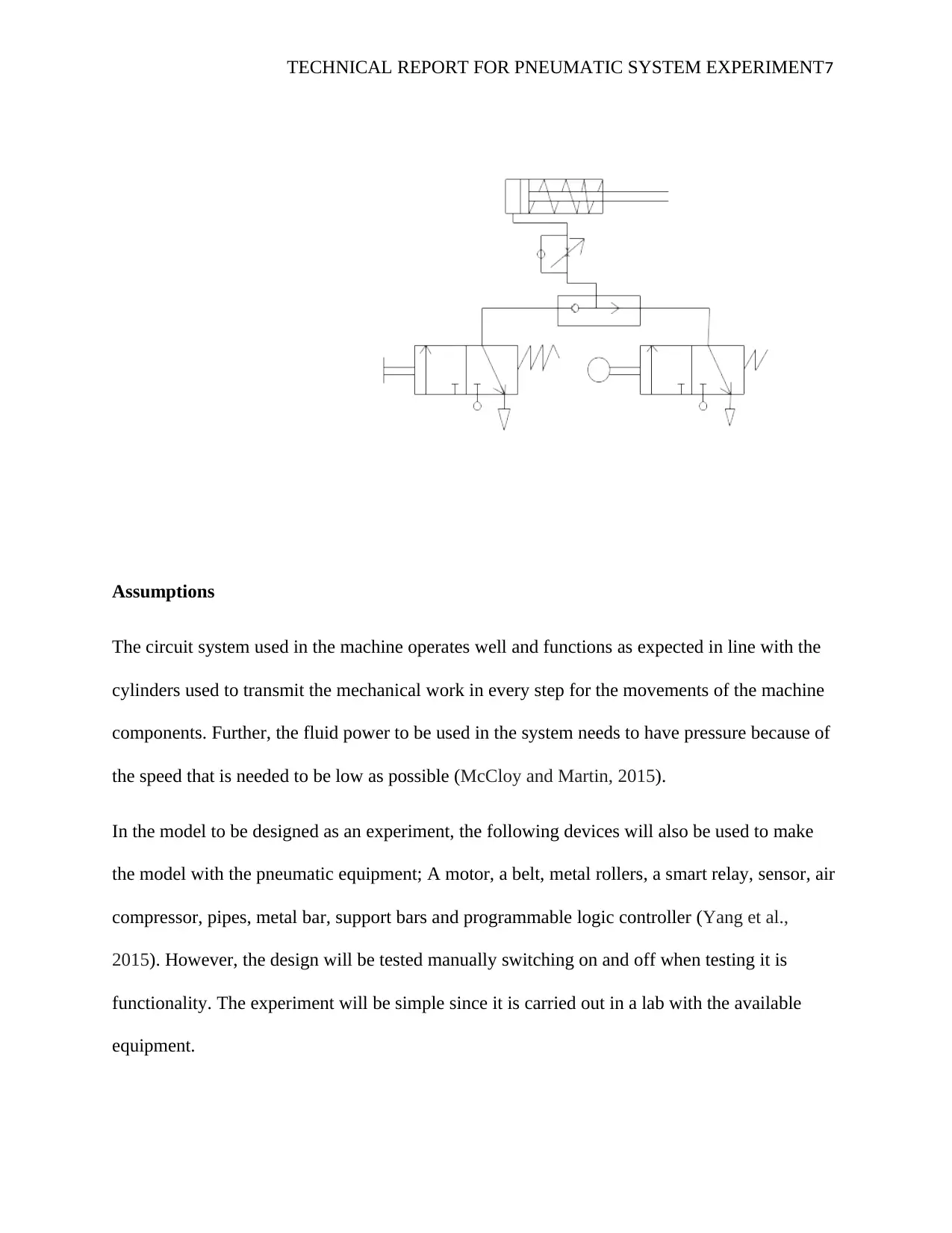
working model of the pneumatic circuit
The system is preferred since air can be used in various temperatures, the machine was
designed for extreme conditions where breakdowns can be minimized.
The plant chooses gas fluids in pneumatics since air is favorable to move at speeds that
are adjustable and therefore when using a cylinder actuator for pneumatic system medium
speed is achieved for the experiment.
Disadvantages of fluid chosen in the machine for the pneumatic system
There is noise from the machine which is unconducive when in operation since the
system used is an open one.
Air condenses easily and it consumes times time since must be processed to meet the
requirements such as to be filtered and dried.
Leakage was an issue to the machine for the pneumatic system more especially when
seals are loose at the joints (Yang et al., 2015).
working model of the pneumatic circuit
⊘ This is a preview!⊘
Do you want full access?
Subscribe today to unlock all pages.
Trusted by 1+ million students worldwide
TECHNICAL REPORT FOR PNEUMATIC SYSTEM EXPERIMENT7
Assumptions
The circuit system used in the machine operates well and functions as expected in line with the
cylinders used to transmit the mechanical work in every step for the movements of the machine
components. Further, the fluid power to be used in the system needs to have pressure because of
the speed that is needed to be low as possible (McCloy and Martin, 2015).
In the model to be designed as an experiment, the following devices will also be used to make
the model with the pneumatic equipment; A motor, a belt, metal rollers, a smart relay, sensor, air
compressor, pipes, metal bar, support bars and programmable logic controller (Yang et al.,
2015). However, the design will be tested manually switching on and off when testing it is
functionality. The experiment will be simple since it is carried out in a lab with the available
equipment.
Paraphrase This Document
Need a fresh take? Get an instant paraphrase of this document with our AI Paraphraser
TECHNICAL REPORT FOR PNEUMATIC SYSTEM EXPERIMENT8
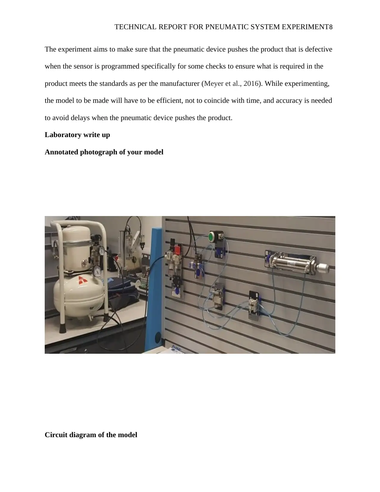
The experiment aims to make sure that the pneumatic device pushes the product that is defective
when the sensor is programmed specifically for some checks to ensure what is required in the
product meets the standards as per the manufacturer (Meyer et al., 2016). While experimenting,
the model to be made will have to be efficient, not to coincide with time, and accuracy is needed
to avoid delays when the pneumatic device pushes the product.
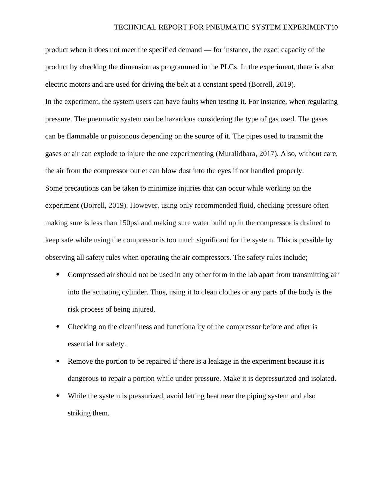
Laboratory write up
Annotated photograph of your model
Circuit diagram of the model
The experiment aims to make sure that the pneumatic device pushes the product that is defective
when the sensor is programmed specifically for some checks to ensure what is required in the
product meets the standards as per the manufacturer (Meyer et al., 2016). While experimenting,
the model to be made will have to be efficient, not to coincide with time, and accuracy is needed
to avoid delays when the pneumatic device pushes the product.
Laboratory write up
Annotated photograph of your model
Circuit diagram of the model
TECHNICAL REPORT FOR PNEUMATIC SYSTEM EXPERIMENT9
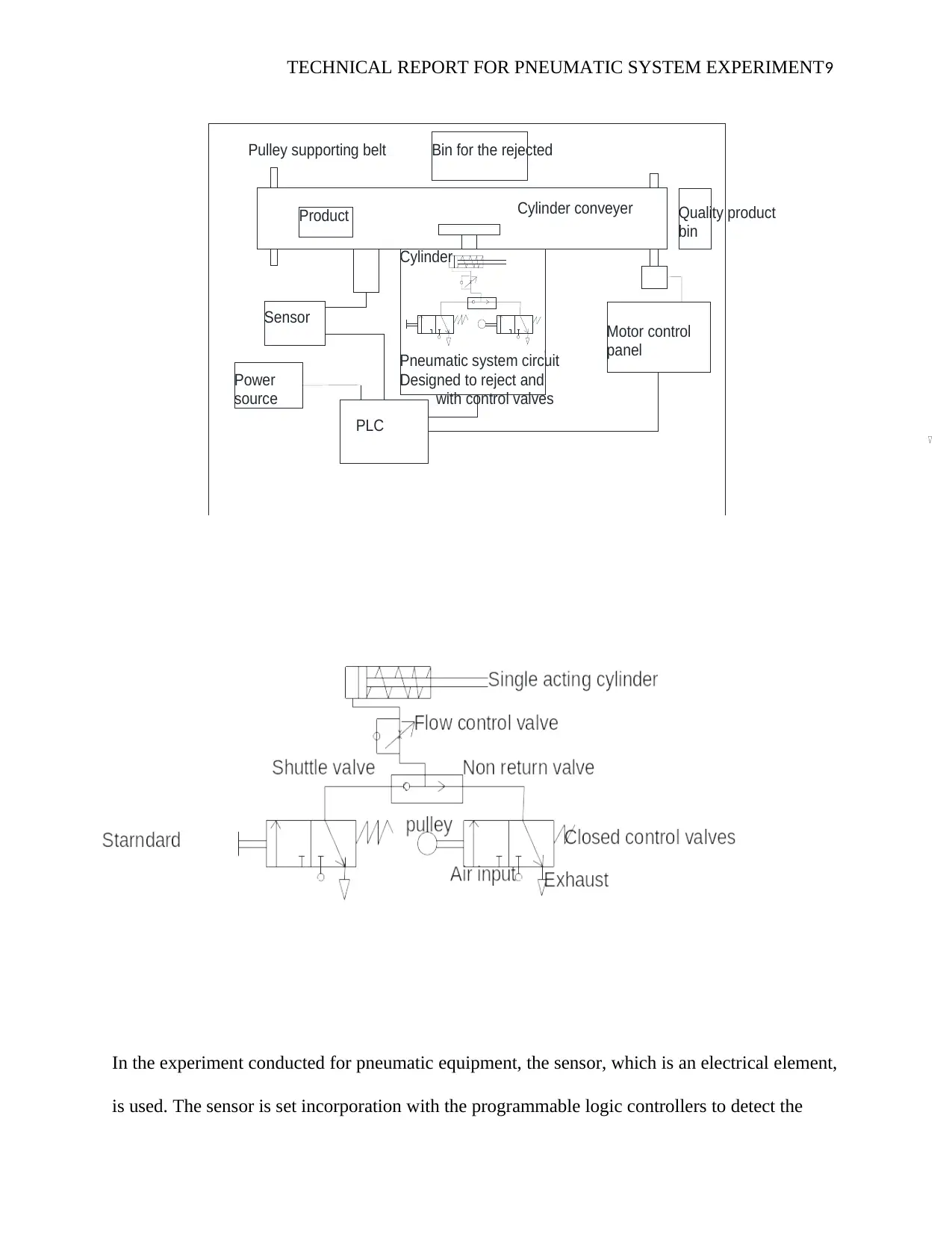
In the experiment conducted for pneumatic equipment, the sensor, which is an electrical element,
is used. The sensor is set incorporation with the programmable logic controllers to detect the
Sensor
with control valves
bin
Pulley supporting belt
PLC
Cylinder
Bin for the rejected
Motor control
Power
Pneumatic system circuit
Cylinder conveyerProduct
panel
source
Designed to reject and
Quality product
⊘ This is a preview!⊘
Do you want full access?
Subscribe today to unlock all pages.
Trusted by 1+ million students worldwide
TECHNICAL REPORT FOR PNEUMATIC SYSTEM EXPERIMENT10
product when it does not meet the specified demand — for instance, the exact capacity of the
product by checking the dimension as programmed in the PLCs. In the experiment, there is also
electric motors and are used for driving the belt at a constant speed (Borrell, 2019).
In the experiment, the system users can have faults when testing it. For instance, when regulating
pressure. The pneumatic system can be hazardous considering the type of gas used. The gases
can be flammable or poisonous depending on the source of it. The pipes used to transmit the
gases or air can explode to injure the one experimenting (Muralidhara, 2017). Also, without care,
the air from the compressor outlet can blow dust into the eyes if not handled properly.
Some precautions can be taken to minimize injuries that can occur while working on the
experiment (Borrell, 2019). However, using only recommended fluid, checking pressure often
making sure is less than 150psi and making sure water build up in the compressor is drained to
keep safe while using the compressor is too much significant for the system. This is possible by
observing all safety rules when operating the air compressors. The safety rules include;
Compressed air should not be used in any other form in the lab apart from transmitting air
into the actuating cylinder. Thus, using it to clean clothes or any parts of the body is the
risk process of being injured.
Checking on the cleanliness and functionality of the compressor before and after is
essential for safety.
Remove the portion to be repaired if there is a leakage in the experiment because it is
dangerous to repair a portion while under pressure. Make it is depressurized and isolated.
While the system is pressurized, avoid letting heat near the piping system and also
striking them.
Paraphrase This Document
Need a fresh take? Get an instant paraphrase of this document with our AI Paraphraser
TECHNICAL REPORT FOR PNEUMATIC SYSTEM EXPERIMENT11
An issue may arise when operating the valves manually. Therefore, it is recommended to
open the valves slowly until the air is seen as it is recommendable to maintain the valve
position for air to equalize.
The gas cylinder for the experiment should not be exposed to temperatures of more than
130 F (Baghban et al. , 2016).
In the experiment, the fluid power system used is efficient. Constant force is applied.
Considering the maintenance of the device, it is economical in terms of it is the production
process. The inspection of the model did not attain the required standards when using the
pneumatic equipment for experimentation (Muralidhara, 2017). Thus, considering all the
materials of quality from the manufacturers will help in making the model design better. When
the project was completed, testing was done which was okay despite the variance in speed to the
detection of fault products deferred a bit because of motors speed and the pneumatic equipment
delay (Kujacznski et al., 2019).
The system could work better with the design by using materials with perfect functionality. For
instance, pipes used to transmit air pressure built to the cylinder. Looking also at the cylinder
stroke of the pneumatic equipment since it has an impact on the force produced from the fluid
applied. Lastly, to increase the efficiency of the system is by making sure connections to
different joining points are sealed completely to avoid leakages that might reduce the efficiency
of the system (Meyer et al., 2016).
Sharing of Efficient Production Methods (SEPM) and PCBR systems
The plant system is designed well to meet; it is working standards as required. The designer of
the machine thought well of the pneumatic component that provided better efficiency for the
working process (Borrell, 2019). According to the senior engineer, the production strategy used
TECHNICAL REPORT FOR PNEUMATIC SYSTEM EXPERIMENT12
in the plant was efficient and therefore, reducing the total average costs used in production per
unit time. Also, job, done, batch, and the flow process when all considered for the production
process to make sure quality is met for the product (Muralidhara, 2017).
Recommendations
In the plant, it could be better to have more checks on product quality by developing
other dimensions in it. Therefore, more smart relay sensors will be needed to fill the gap
and improve the check of the product (Borrell, 2019).
To manufacture quality products in the market, there is no alternative to accuracy in
production. If the production level is increased with more accuracy price will be cheaper
than the current manufacturing cost. Thus developing a simple design and put the
available sensors in place, products will be cheaper (McCloy and Martin, 2015).
The machine needs to be redesigned to check different bottles of sizes and dimensionals
accuracy.
References
⊘ This is a preview!⊘
Do you want full access?
Subscribe today to unlock all pages.
Trusted by 1+ million students worldwide
1 out of 14
Related Documents


Your All-in-One AI-Powered Toolkit for Academic Success.
+13062052269
info@desklib.com
Available 24*7 on WhatsApp / Email
![[object Object]](/_next/static/media/star-bottom.7253800d.svg)
Unlock your academic potential
Copyright © 2020–2026 A2Z Services. All Rights Reserved. Developed and managed by ZUCOL.