Electromagnetic Braking System: Design and Analysis Report
VerifiedAdded on 2023/06/05
|15
|2798
|367
Report
AI Summary
This report presents a comprehensive overview of an electromagnetic braking system, addressing its design, analysis, and evaluation. The introduction highlights the advantages of electromagnetic braking over traditional systems, emphasizing efficiency and low failure rates. The preliminary design section details the working principles, components such as the hub, armature, field, disc liner, and backing coil, and the role of the battery and tension spring. The final design focuses on the system's ability to stop heavy and medium vehicles, ensuring the generated torque exceeds the vehicle's torque. System tests, including brake disengaged and engaged scenarios, validate the design's effectiveness. The evaluation section discusses assembly, maintenance, and functionality. The report concludes with a discussion on the future scope of electromagnetic braking systems, including their potential in the automotive industry and other applications. The report includes figures to visualize the working principle of the system.
Running head: ELECTOMAGNETIC BRAKING SYSTEM
ELECTOMAGNETIC BRAKING SYSTEM
Name of the Student
Name of the University
Author Note
ELECTOMAGNETIC BRAKING SYSTEM
Name of the Student
Name of the University
Author Note
Paraphrase This Document
Need a fresh take? Get an instant paraphrase of this document with our AI Paraphraser
1ELECTOMAGNETIC BRAKING SYSTEM
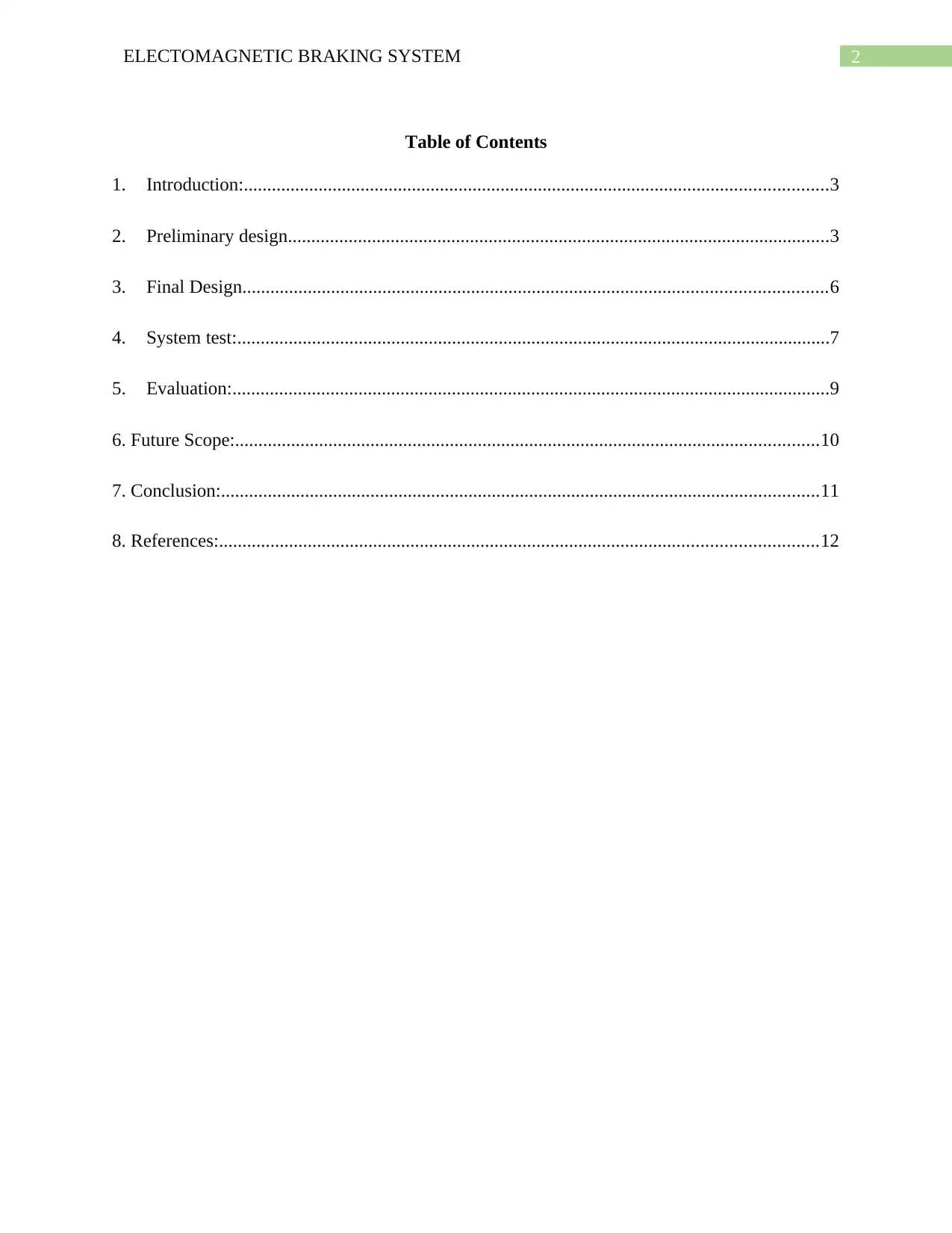
Executive Summary:
In populated states, accidents are frequently occurs due to the congestion of the vehicles. Even
though, the advanced technologies provide enhance driving experience with optimal security
measures. Often, casualties occurs while trying to stop car in a short time or suddenly. Drivers
would not able to control the car after initiating the break mechanism. This type of causalities
leads to heavy capital loss and put humans in danger. To overcome this type of casualties an
emergency breaking system has been proposed which would be capable of stopping cars in a
short amount of time while utilizing electromagnetic mechanism. The conceptual design of the
electromagnetic system has been proposed with proper figures to visualize the working principle.
2ELECTOMAGNETIC BRAKING SYSTEM
Table of Contents
1. Introduction:.............................................................................................................................3
2. Preliminary design....................................................................................................................3
3. Final Design.............................................................................................................................6
4. System test:...............................................................................................................................7
5. Evaluation:................................................................................................................................9
6. Future Scope:.............................................................................................................................10
7. Conclusion:................................................................................................................................11
8. References:................................................................................................................................12
⊘ This is a preview!⊘
Do you want full access?
Subscribe today to unlock all pages.
Trusted by 1+ million students worldwide
3ELECTOMAGNETIC BRAKING SYSTEM
1. Introduction:
Electromagnetic breaking system is one of the most reliable breaking system in terms of
efficiency and effectiveness. The failure rate of air and oil breaking system has been a critical
issue and could lead to failure of breaks. Electromagnetic braking system can be very effective
and reliable and has a low failure rate compare to the other breaking system. If one of the coil of
the electromagnetic braking system is fails, the whole breaking system will not work properly
instead of stop working. The system design contains two magnet body and two electric coils for
constructing enough amount of flux which will flow from magnet body to the armatures situated
around the coils. In the output plate, two teeth have been installed. Further, the preliminary
design and detailed designed has been demonstrated with development. After finalizing the
design, a system analysis is also conducted to check the effectiveness and identify certain risks
(Sharma, Dhingra and Pathak 2015). The proposed design of the braking system is compromised
with both electric and mechanical components. Even though the typical braking system can offer
same functionality as the electromagnetic braking system. Electromagnetic braking system
allows to control the magnetic field through current.
2. Preliminary design
The working principle of the electromagnetism is totally depends on the magnetic field.
When certain quantity of current is distributed through a round conductor then it produces
magnetic field which is uniform all over the conductor. The current flowing through the
conductor cause the magnetic field alteration. The base principle of the system follows the right
hand rule. As demonstrate in the figures, electromagnetic brake is mainly consist of Hub,
Armature and filed. If the armature field is involved near the magnetic field the breaking torque
is into the machine frame decelerating the load and transported into the field housing (Zheng and
Paraphrase This Document
Need a fresh take? Get an instant paraphrase of this document with our AI Paraphraser
4ELECTOMAGNETIC BRAKING SYSTEM
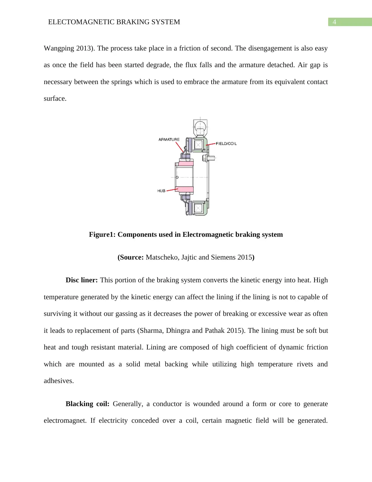
Wangping 2013). The process take place in a friction of second. The disengagement is also easy
as once the field has been started degrade, the flux falls and the armature detached. Air gap is
necessary between the springs which is used to embrace the armature from its equivalent contact
surface.
Figure1: Components used in Electromagnetic braking system
(Source: Matscheko, Jajtic and Siemens 2015)
Disc liner: This portion of the braking system converts the kinetic energy into heat. High
temperature generated by the kinetic energy can affect the lining if the lining is not to capable of
surviving it without our gassing as it decreases the power of breaking or excessive wear as often
it leads to replacement of parts (Sharma, Dhingra and Pathak 2015). The lining must be soft but
heat and tough resistant material. Lining are composed of high coefficient of dynamic friction
which are mounted as a solid metal backing while utilizing high temperature rivets and
adhesives.
Blacking coil: Generally, a conductor is wounded around a form or core to generate
electromagnet. If electricity conceded over a coil, certain magnetic field will be generated.
5ELECTOMAGNETIC BRAKING SYSTEM
Winding or turn is referred to a loop of wire which consist of one or more wounds (Sharma,
Dhingra and Pathak 2015). Taps are the electrical connection terminals which is frequently used
as electronic circuit. This taps are wounded around a coil which could be coated with wrapped
and varnish along with insulating tape in order to generate secure and additional insulation in the
area. Windings are referred to coil which are assembly with more or one set of taps(Panosyan et
al. 2016).
Tension Spring: Tension spring is used to store mechanical energy as an elastic
component. Appropriateness of spring could be differ depending on the operation environment,
build material and design. Generally, springs could be constructed with lot of various type of
materials. If the spring is in compressed, the force is exerted is proportional to its change in
length. It generates a strong magnetic field while wire passes through the canter of the coil
(Sharma, Dhingra and Pathak 2015). There are a huge advantage of the electromagnet over the
permanent magnet. In the electro magnet the magnetic field can be controlled through the
electric current.
Battery: A battery is used to convert chemical energy to electrical energy. Generally this
type of batteries are consist of few voltaic cells which consist of two half cells containing cations
and anions. Two cells contains different electrodes which are separated with each other. The
separation enables the ions flow and also prevents mixing the electrolytes. The electromotive
force of half cells are determined by the ability (Bachmann 2014). To drive electric current from
the peripheral to the outward of the cell. The net EMF of the cell is the alteration among the
EMF of its half-cells which was initially predicted by Volta. Therefore, if the electrodes are
consist of EMF and, then the net EMF is in other words, the net EMF is the variance concerning
the decrease capacities of the half-reactions.
⊘ This is a preview!⊘
Do you want full access?
Subscribe today to unlock all pages.
Trusted by 1+ million students worldwide
6ELECTOMAGNETIC BRAKING SYSTEM
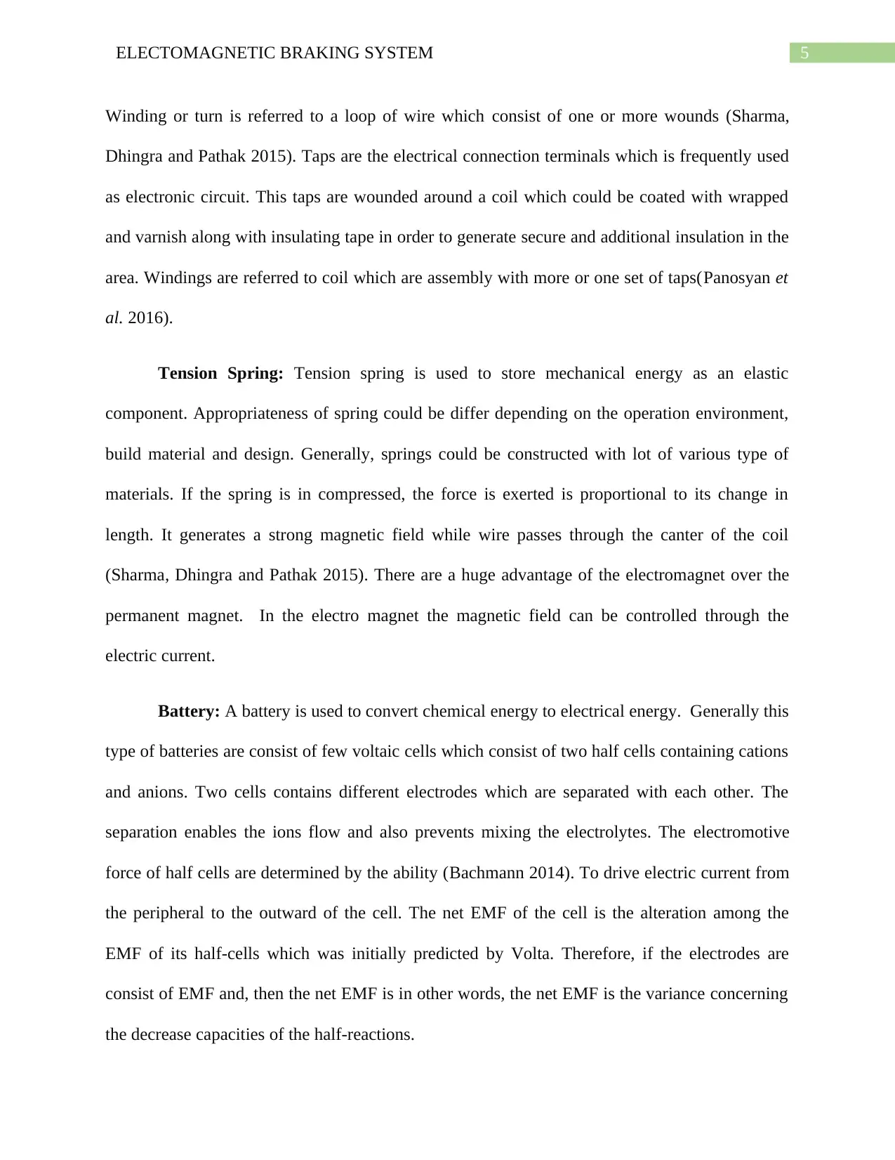
3. Final Design
The system has been designed accordingly which is capable of generating required force
to stop heavy and medium vehicles without losing control over the automobile . The designed are
constructed while assuring that the generated torque by breakers is high enough to cross the
torque of the vehicles (Sharma, Dhingra and Pathak 2015). The proposed design is also
appropriate to transform kinetic energy into heat energy. The breaks will be almost follow the
same principle of typical brakes. However, it is more effective than the typical breaks as the
operation could be controlled through electric as the power source for transmitting the torque
mechanically (Lostado et al. 2016). The proposed system is encompassed of two separate bodies
along with two electric coils to generate enough flux. The flux will flow through the magnet
body to the armatures the coil. The springs are also comprised to enable high electromagnetic
filed. One of the most important aspect of the system is it is capable of operate in both dry and
oil medium. Specification of the proposed design is following:
Design modifications and assembly customization can be made in easy ways
Paraphrase This Document
Need a fresh take? Get an instant paraphrase of this document with our AI Paraphraser
7ELECTOMAGNETIC BRAKING SYSTEM
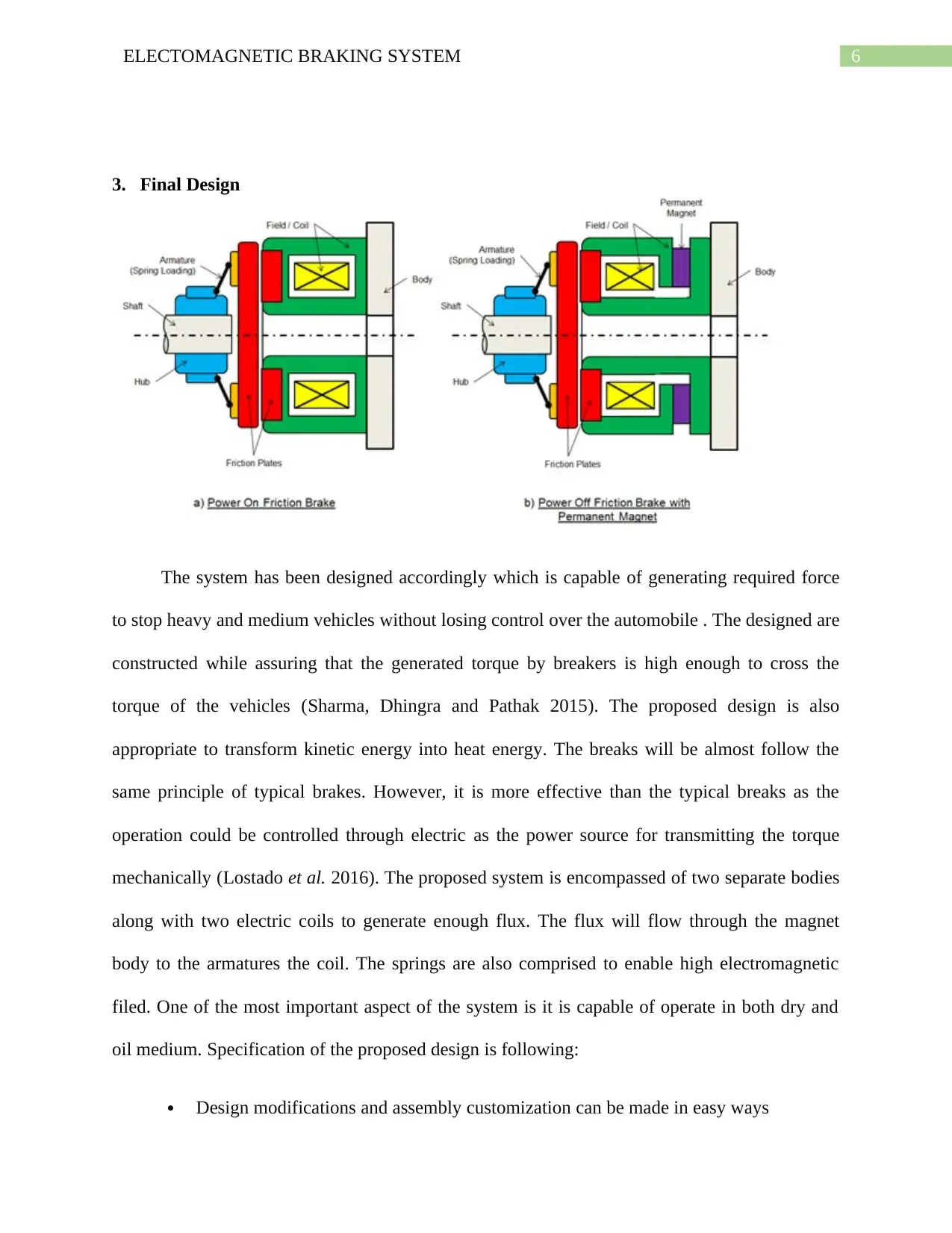
The maximum attained speed varies from 1800 to 5500 RPM
Operatable in both oil and in dry
The bore sizes varies from 1.2 to 5.1”
The static torque developed varies from 20 to 2600 lb-ft
1.4 to 6.5” length; 2.8 to 9.6” diameter
4. System test:
The system was checked properly in order to identify any certain problems while
conducting breaking information. System test is necessary in order understand the project
progression and successfulness. To evaluate the proposed design the system is analysed and the
results are measured for validation (Sharma, Dhingra and Pathak 2015). There are mainly two
cases which needs to be validate, in presence of current and presence of current. This two cases
resembles the brake disengaged and brake engaged scenario.
Brake disengaged: In the state where the electromagnet is invigorated by the movement
of electricity in the windings as a result it attracts the disc near itself. While in these process it
correspondents the spring alongside the electromagnet. The free variation of cork is initiated
which could be connected to shaft along with an integral hub, engaged with iron disc. (Sharma,
Dhingra and Pathak 2015). It enable the power flow from the propeller shaft to rear axle without
facing type of disruption.
Brake engaged: When driver initiates the brakes of electromagnetic breaking system, it
just cut off the electric supply to the electromagnet, as a result the iron disc which was
The maximum attained speed varies from 1800 to 5500 RPM
Operatable in both oil and in dry
The bore sizes varies from 1.2 to 5.1”
The static torque developed varies from 20 to 2600 lb-ft
1.4 to 6.5” length; 2.8 to 9.6” diameter
4. System test:
The system was checked properly in order to identify any certain problems while
conducting breaking information. System test is necessary in order understand the project
progression and successfulness. To evaluate the proposed design the system is analysed and the
results are measured for validation (Sharma, Dhingra and Pathak 2015). There are mainly two
cases which needs to be validate, in presence of current and presence of current. This two cases
resembles the brake disengaged and brake engaged scenario.
Brake disengaged: In the state where the electromagnet is invigorated by the movement
of electricity in the windings as a result it attracts the disc near itself. While in these process it
correspondents the spring alongside the electromagnet. The free variation of cork is initiated
which could be connected to shaft along with an integral hub, engaged with iron disc. (Sharma,
Dhingra and Pathak 2015). It enable the power flow from the propeller shaft to rear axle without
facing type of disruption.
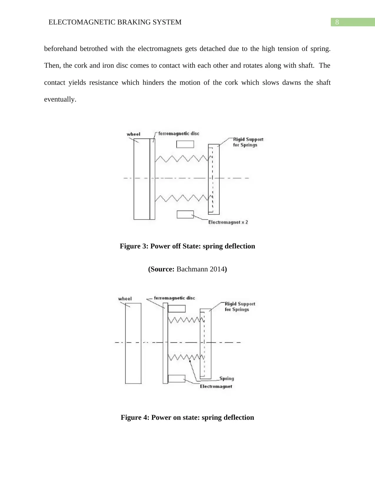
Brake engaged: When driver initiates the brakes of electromagnetic breaking system, it
just cut off the electric supply to the electromagnet, as a result the iron disc which was
8ELECTOMAGNETIC BRAKING SYSTEM
beforehand betrothed with the electromagnets gets detached due to the high tension of spring.
Then, the cork and iron disc comes to contact with each other and rotates along with shaft. The
contact yields resistance which hinders the motion of the cork which slows dawns the shaft
eventually.
Figure 3: Power off State: spring deflection
(Source: Bachmann 2014)
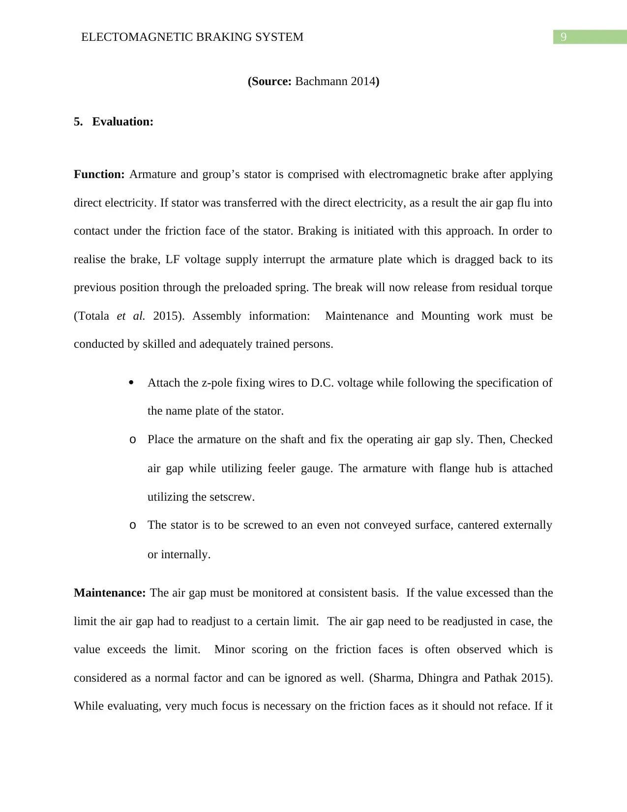
Figure 4: Power on state: spring deflection
beforehand betrothed with the electromagnets gets detached due to the high tension of spring.
Then, the cork and iron disc comes to contact with each other and rotates along with shaft. The
contact yields resistance which hinders the motion of the cork which slows dawns the shaft
eventually.
Figure 3: Power off State: spring deflection
(Source: Bachmann 2014)
Figure 4: Power on state: spring deflection
⊘ This is a preview!⊘
Do you want full access?
Subscribe today to unlock all pages.
Trusted by 1+ million students worldwide
9ELECTOMAGNETIC BRAKING SYSTEM
(Source: Bachmann 2014)
5. Evaluation:
Function: Armature and group’s stator is comprised with electromagnetic brake after applying
direct electricity. If stator was transferred with the direct electricity, as a result the air gap flu into
contact under the friction face of the stator. Braking is initiated with this approach. In order to
realise the brake, LF voltage supply interrupt the armature plate which is dragged back to its
previous position through the preloaded spring. The break will now release from residual torque
(Totala et al. 2015). Assembly information: Maintenance and Mounting work must be
conducted by skilled and adequately trained persons.
Attach the z-pole fixing wires to D.C. voltage while following the specification of
the name plate of the stator.
o Place the armature on the shaft and fix the operating air gap sly. Then, Checked
air gap while utilizing feeler gauge. The armature with flange hub is attached
utilizing the setscrew.
o The stator is to be screwed to an even not conveyed surface, cantered externally
or internally.
Maintenance: The air gap must be monitored at consistent basis. If the value excessed than the
limit the air gap had to readjust to a certain limit. The air gap need to be readjusted in case, the
value exceeds the limit. Minor scoring on the friction faces is often observed which is
considered as a normal factor and can be ignored as well. (Sharma, Dhingra and Pathak 2015).
While evaluating, very much focus is necessary on the friction faces as it should not reface. If it
Paraphrase This Document
Need a fresh take? Get an instant paraphrase of this document with our AI Paraphraser
10ELECTOMAGNETIC BRAKING SYSTEM
happens, the existed functionality of the braking system can be effected. The brakes can be
readjusted several time till the readjusted limit exceeds. In that case, brake needs to be replaced.
6. Future Scope:
As the technology is evolving rapidly, the application of such technologies is adopted by
various sector including the automobile industry. There are several research currently taking
places to develop and enhance a better braking system. The innovation around braking system is
considered as a one of the hot topic. The enhanced breaking system will not only assist to stop
automobiles, it will also assist to prevent accidents in populated area. For instance,
Electromagnetic braking system can be designed to hold robotic equipment which can help to
prevent damage of such equipment during power loss. Further, the electromagnetic braking
system prevent the danger that can occur from the extended use of brake beyond their
competency to dissipate hot temperature.

11ELECTOMAGNETIC BRAKING SYSTEM
⊘ This is a preview!⊘
Do you want full access?
Subscribe today to unlock all pages.
Trusted by 1+ million students worldwide
1 out of 15
Related Documents


Your All-in-One AI-Powered Toolkit for Academic Success.
+13062052269
info@desklib.com
Available 24*7 on WhatsApp / Email
![[object Object]](/_next/static/media/star-bottom.7253800d.svg)
Unlock your academic potential
Copyright © 2020–2026 A2Z Services. All Rights Reserved. Developed and managed by ZUCOL.