Comprehensive Report on Electronic Fuel Injection System Analysis

Verified

Added on  2023/04/25

|5
|881
|327
Report
AI Summary
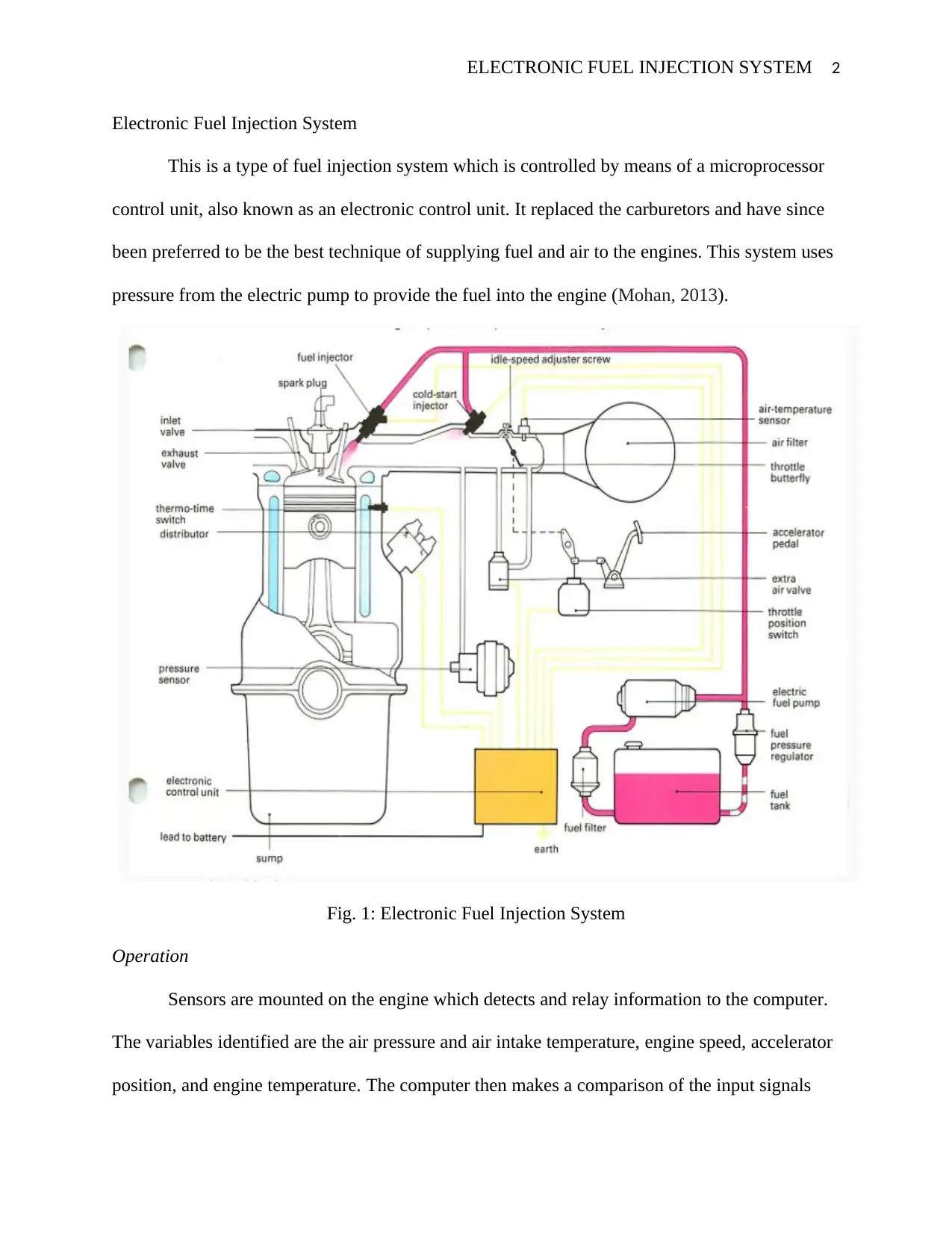
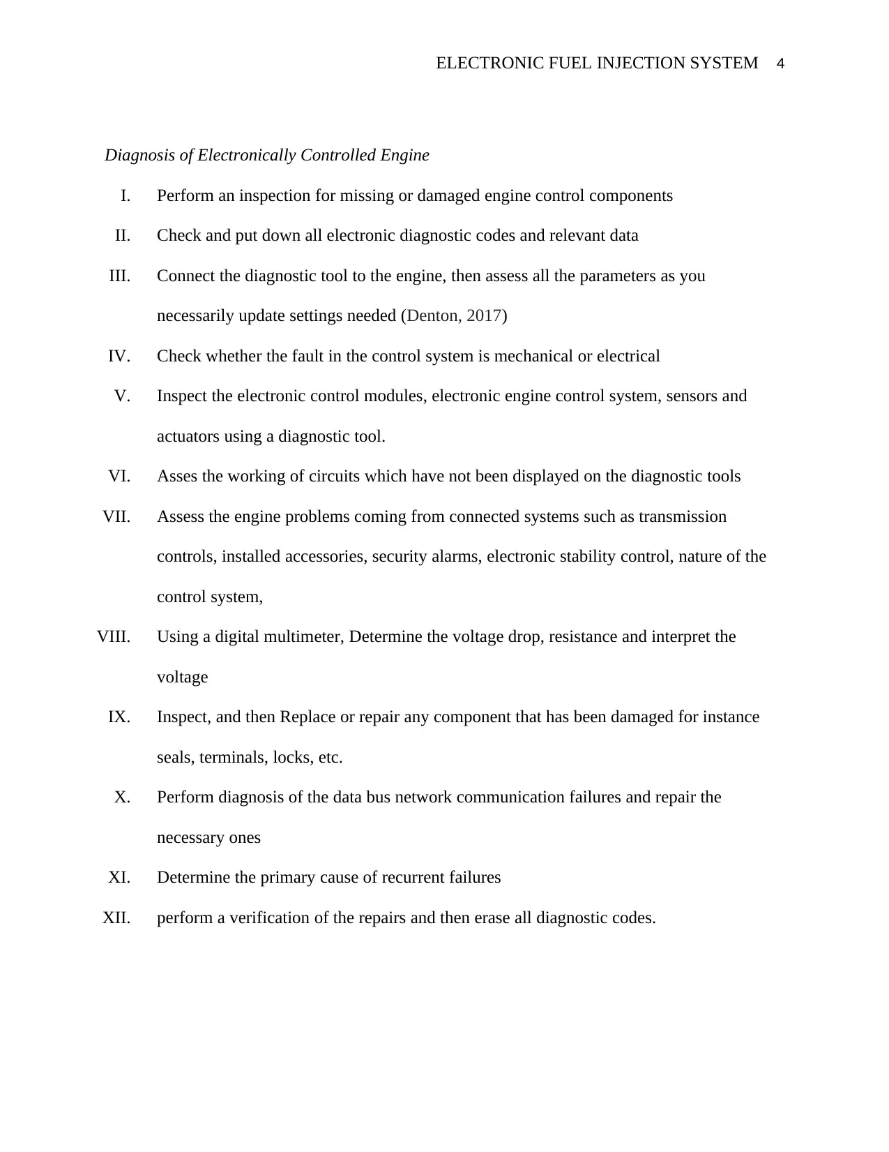
This report provides an overview of the electronic fuel injection (EFI) system, a microprocessor-controlled system used in engines to replace carburetors. It details the system's operation, including the role of sensors in detecting engine conditions such as air pressure, temperature, engine speed, and accelerator position, which are then relayed to the computer (ECU). The ECU compares these inputs with programmed information to determine the appropriate amount of fuel to inject. The report also describes key components like the Electronic Control Module, engine sensors, injector actuators, and electronically controlled unit injectors. Furthermore, it outlines a step-by-step process for diagnosing electronically controlled engine issues, including inspecting components, checking diagnostic codes, assessing mechanical and electrical faults, and verifying repairs. The document also covers the diagnosis of data bus network communication failures and recurrent failures.
Document Page
ELECTRONIC FUEL INJECTION SYSTEM 1
ELECTRONIC FUEL INJECTION SYSTEM
Name of student
Course
Tutor
Institution affiliation
Location
Date
tabler-icon-diamond-filled.svg

Paraphrase This Document

Need a fresh take? Get an instant paraphrase of this document with our AI Paraphraser
Document Page
ELECTRONIC FUEL INJECTION SYSTEM 2
Electronic Fuel Injection System
This is a type of fuel injection system which is controlled by means of a microprocessor
control unit, also known as an electronic control unit. It replaced the carburetors and have since
been preferred to be the best technique of supplying fuel and air to the engines. This system uses
pressure from the electric pump to provide the fuel into the engine (Mohan, 2013).
Fig. 1: Electronic Fuel Injection System
Operation
Sensors are mounted on the engine which detects and relay information to the computer.
The variables identified are the air pressure and air intake temperature, engine speed, accelerator
position, and engine temperature. The computer then makes a comparison of the input signals
Document Page
ELECTRONIC FUEL INJECTION SYSTEM 3
with the already programmed information and after that decides on how much fuel should be
allowed in. After that, it signals the on-off valve to allow fuel into the port inlet. These
operations happen at very instant speed, as well as detection of the air pressure, temperature and
acceleration position (Ehresman et al., 2011). Electronic Control Module - This is a control module which determines the various
parameters which should be allowed into the system, such as ignition timing, amount of
fuel, and internal combustion engine parameters. The ECU operates by reading the
multidimensional map values that are detected by the sensor devices.
Engine Sensors- These are devices that detect changes in the engine conditions and then
transmit the signals to the computer. They operate by reading various changes in the
engine conditions such as temperature, pressure, and speed and then convert them to
electrical signals upon which they transmit to the controller for control actions.
Injector Actuators- These are mechanical control devices positioned at the center of the
control system for actual control of the injected fuel in the cylinder of the engine. They
operate alongside hydraulic amplifier whereby it displaces the needle at the output of the
injector orifice hence allowing the flow of fuel. It is operated by an electrical circuit
which is controlled by a control module.
Electronically Controlled Unit Injectors - This is a unit injector having an electronic
control and operates in the same manner as the conventional unit injector by injecting the
fuel into the cylinder. However, its nozzle has a solenoid-controlled spill valve that is
usually open thus allowing fuel to flow in reverse back to the supply line upon plunging
of the pump plunger. When the solenoid gets activated, the spill valve closes allowing
fuel t get into the spray to the cylinder (Sáinz et al., 2013).
Document Page
ELECTRONIC FUEL INJECTION SYSTEM 4
Diagnosis of Electronically Controlled Engine
I. Perform an inspection for missing or damaged engine control components
II. Check and put down all electronic diagnostic codes and relevant data
III. Connect the diagnostic tool to the engine, then assess all the parameters as you
necessarily update settings needed (Denton, 2017)
IV. Check whether the fault in the control system is mechanical or electrical
V. Inspect the electronic control modules, electronic engine control system, sensors and
actuators using a diagnostic tool.
VI. Asses the working of circuits which have not been displayed on the diagnostic tools
VII. Assess the engine problems coming from connected systems such as transmission
controls, installed accessories, security alarms, electronic stability control, nature of the
control system,
VIII. Using a digital multimeter, Determine the voltage drop, resistance and interpret the
voltage
IX. Inspect, and then Replace or repair any component that has been damaged for instance
seals, terminals, locks, etc.
X. Perform diagnosis of the data bus network communication failures and repair the
necessary ones
XI. Determine the primary cause of recurrent failures
XII. perform a verification of the repairs and then erase all diagnostic codes.
tabler-icon-diamond-filled.svg

Paraphrase This Document

Need a fresh take? Get an instant paraphrase of this document with our AI Paraphraser
Document Page
ELECTRONIC FUEL INJECTION SYSTEM 5
References
Denton, T., 2017. Automobile electrical and electronic systems. Routledge.
Ehresman, T.E., Point Man Aeronautics LLC, 2011. Fuel injection stream parallel opposed
multiple electrode spark gap for fuel injector. U.S. Patent 8,069,836.
Mohan, B., Yang, W. and kiang Chou, S., 2013. Fuel injection strategies for performance
improvement and emissions reduction in compression ignition engines—A
review. Renewable and Sustainable Energy Reviews, 28, pp.664-676.
Sáinz, D., Diéguez, P.M., Urroz, J.C., Sopena, C., Guelbenzu, E., Pérez-Ezcurdia, A., Benito-
Amurrio, M., Marcelino-Sadaba, S., Arzamendi, G. and Gandia, L.M., 2011.
Conversion of a gasoline engine-generator set to a bi-fuel (hydrogen/gasoline)
electronic fuel-injected power unit. International journal of hydrogen energy, 36(21),
pp.13781-13792
chevron_up_icon
1 out of 5
circle_padding
hide_on_mobile
zoom_out_icon
[object Object]