Electronics Assignment: Microwave Transmission Analysis Report

Verified

Added on  2022/10/19

|5
|415
|2
Report
AI Summary
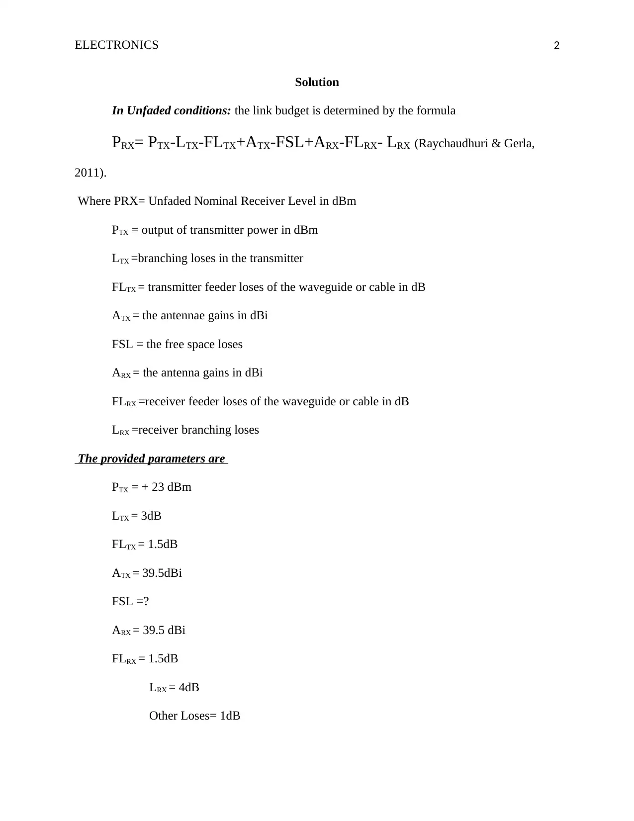
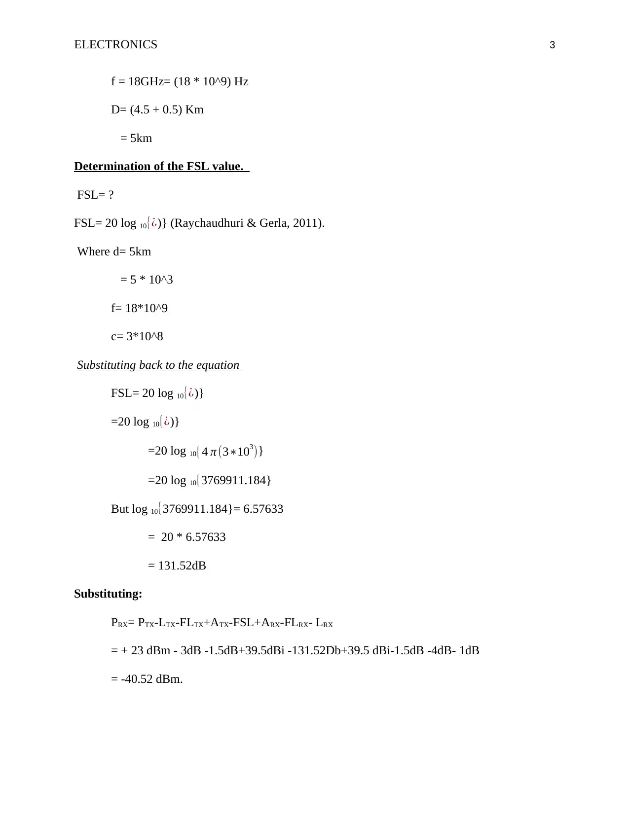
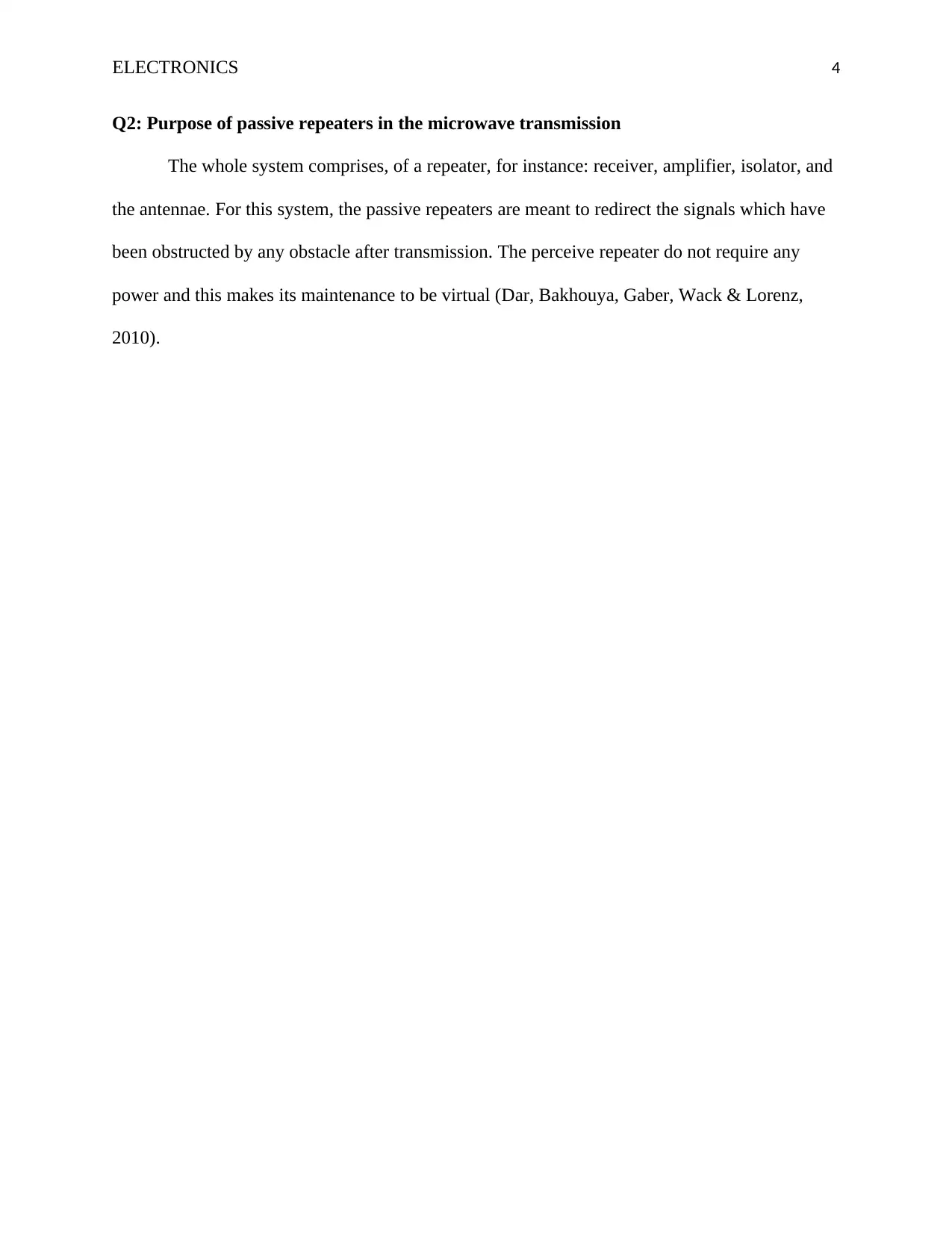
This report presents a solution to an electronics assignment focusing on microwave transmission analysis. The assignment involves calculating the link budget, which includes parameters such as transmitter power, antenna gains, feeder losses, and free space loss. The solution demonstrates the calculation of free space loss using the provided formula and then determines the received power level. Additionally, the report discusses the purpose of passive repeaters in microwave transmission, highlighting their role in redirecting signals and overcoming obstructions without requiring power. The report references relevant literature to support the analysis and findings.
Document Page
Running head: ELECTRONICS 1
Electronics
Name of Student
Institution Affiliation
tabler-icon-diamond-filled.svg

Secure Best Marks with AI Grader

Need help grading? Try our AI Grader for instant feedback on your assignments.
Document Page
ELECTRONICS 2
Solution
In Unfaded conditions: the link budget is determined by the formula
PRX= PTX-LTX-FLTX+ATX-FSL+ARX-FLRX- LRX (Raychaudhuri & Gerla,
2011).
Where PRX= Unfaded Nominal Receiver Level in dBm
PTX = output of transmitter power in dBm
LTX =branching loses in the transmitter
FLTX = transmitter feeder loses of the waveguide or cable in dB
ATX = the antennae gains in dBi
FSL = the free space loses
ARX = the antenna gains in dBi
FLRX =receiver feeder loses of the waveguide or cable in dB
LRX =receiver branching loses
The provided parameters are
PTX = + 23 dBm
LTX = 3dB
FLTX = 1.5dB
ATX = 39.5dBi
FSL =?
ARX = 39.5 dBi
FLRX = 1.5dB
LRX = 4dB
Other Loses= 1dB
Document Page
ELECTRONICS 3
f = 18GHz= (18 * 10^9) Hz
D= (4.5 + 0.5) Km
= 5km
Determination of the FSL value.
FSL= ?
FSL= 20 log 10{¿)} (Raychaudhuri & Gerla, 2011).
Where d= 5km
= 5 * 10^3
f= 18*10^9
c= 3*10^8
Substituting back to the equation
FSL= 20 log 10{¿)}
=20 log 10{¿)}
=20 log 10{4 π (3103)}
=20 log 10{3769911.184}
But log 10{3769911.184}= 6.57633
= 20 * 6.57633
= 131.52dB
Substituting:
PRX= PTX-LTX-FLTX+ATX-FSL+ARX-FLRX- LRX
= + 23 dBm - 3dB -1.5dB+39.5dBi -131.52Db+39.5 dBi-1.5dB -4dB- 1dB
= -40.52 dBm.
Document Page
ELECTRONICS 4
Q2: Purpose of passive repeaters in the microwave transmission
The whole system comprises, of a repeater, for instance: receiver, amplifier, isolator, and
the antennae. For this system, the passive repeaters are meant to redirect the signals which have
been obstructed by any obstacle after transmission. The perceive repeater do not require any
power and this makes its maintenance to be virtual (Dar, Bakhouya, Gaber, Wack & Lorenz,
2010).
tabler-icon-diamond-filled.svg

Secure Best Marks with AI Grader

Need help grading? Try our AI Grader for instant feedback on your assignments.
Document Page
ELECTRONICS 5
References
Dar, K., Bakhouya, M., Gaber, J., Wack, M., & Lorenz, P. (2010). Wireless communication
technologies for ITS applications [Topics in Automotive Networking]. IEEE
Communications Magazine, 48(5), 156-162.
Raychaudhuri, D., & Gerla, M. (Eds.). (2011). Emerging wireless technologies and the future
mobile internet. Cambridge University Press.
chevron_up_icon
1 out of 5
circle_padding
hide_on_mobile
zoom_out_icon
logo.png

Your All-in-One AI-Powered Toolkit for Academic Success.

Available 24*7 on WhatsApp / Email

[object Object]