Electronics Assignment Solution: Receiver Circuit and Electromagnet
VerifiedAdded on 2023/01/18
|8
|937
|93
Homework Assignment
AI Summary
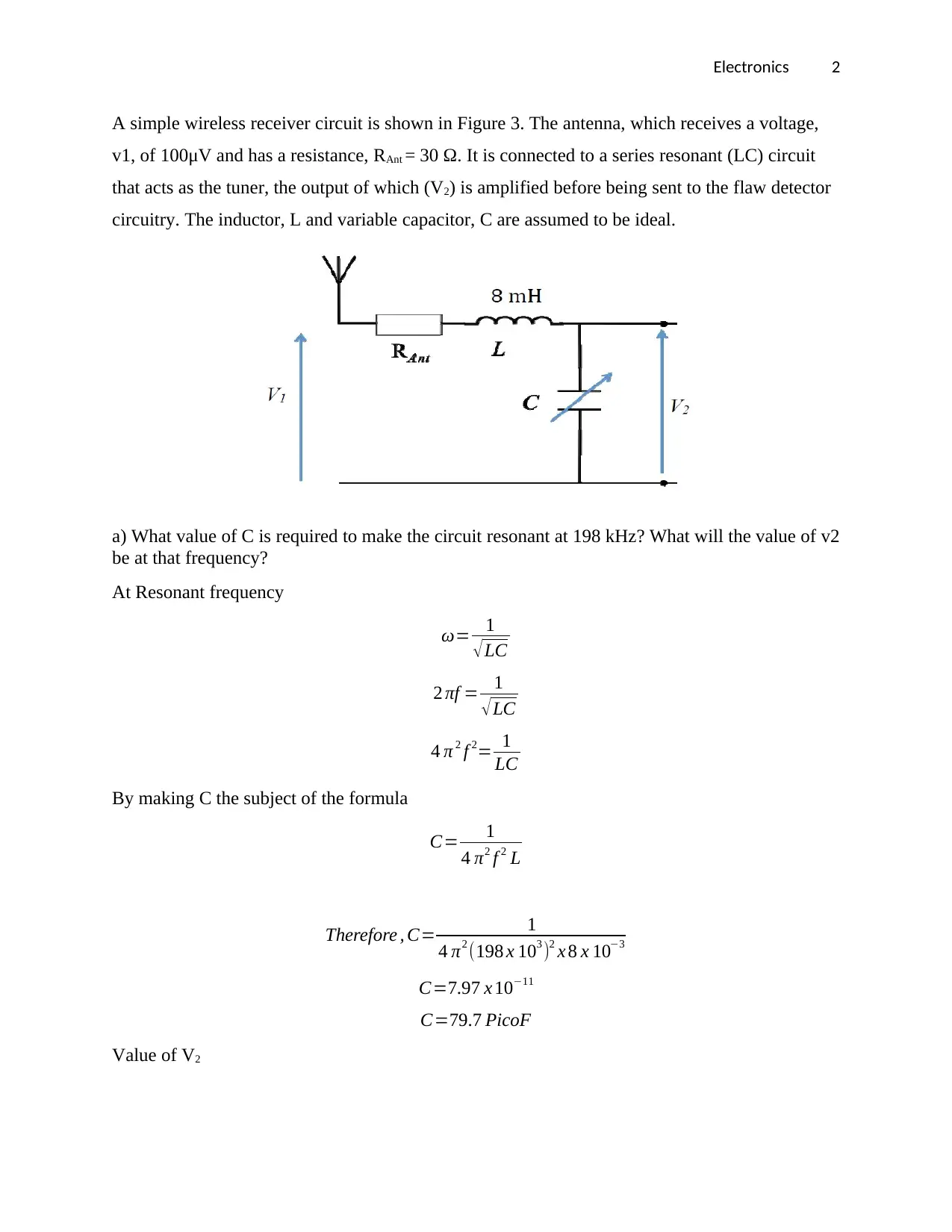
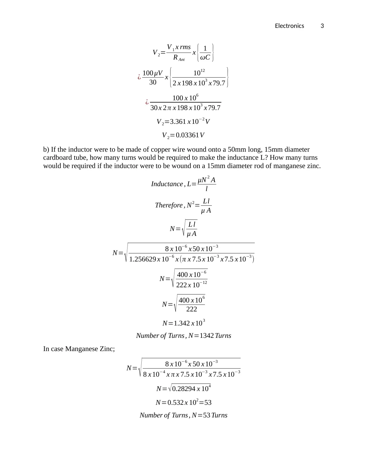
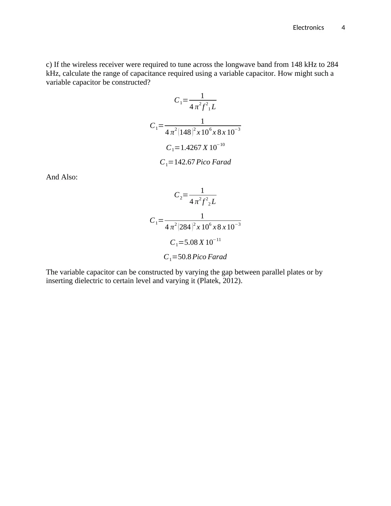
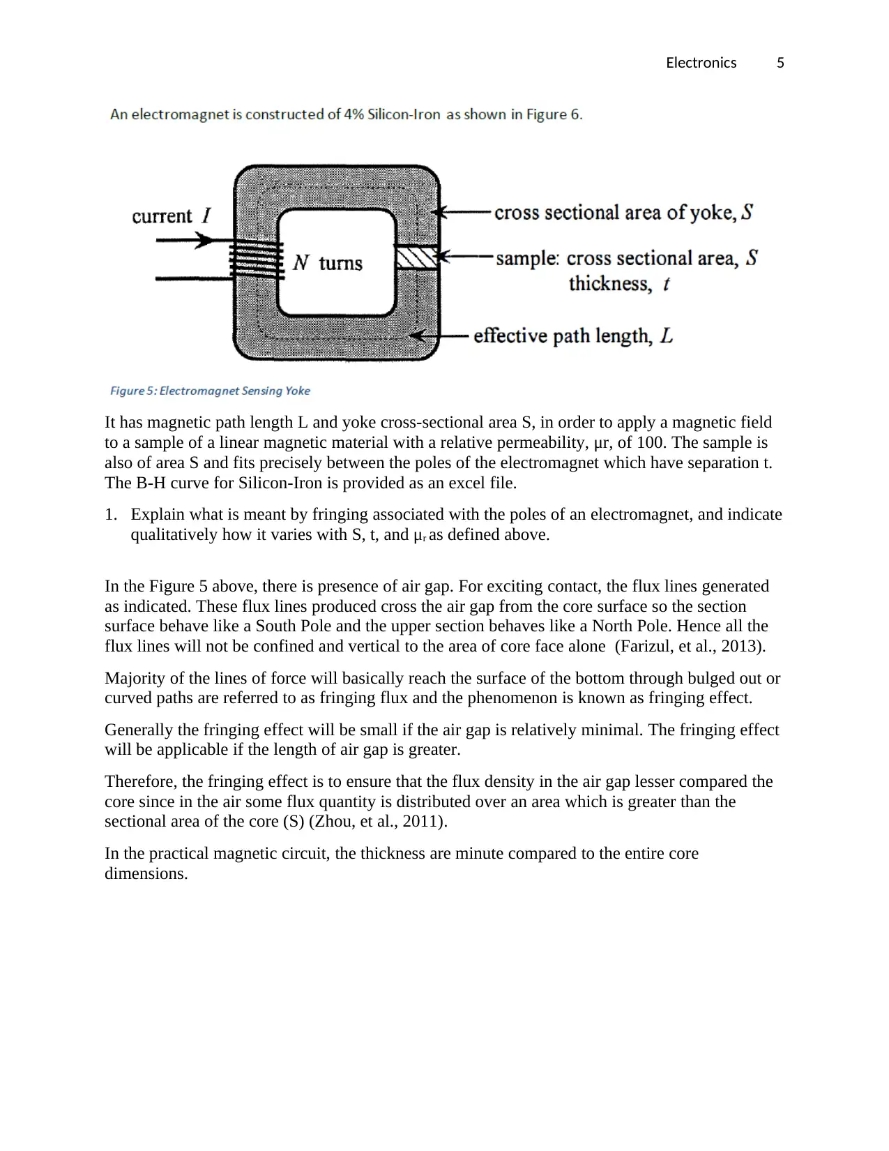
This document provides a comprehensive solution to an electronics assignment. The assignment focuses on a wireless receiver circuit, including calculating the required capacitance for resonance at a specific frequency, determining the number of turns for an inductor based on different core materials, and calculating the range of capacitance for a variable capacitor. Additionally, the assignment delves into electromagnetism, explaining fringing effects associated with electromagnet poles, calculating magnetic flux density, and analyzing how inductance varies with changes in the yoke and sample area, as well as with varying DC current. The solution includes detailed calculations, explanations, and references to support the answers.

Electronics 1
ELECTRONICS
By Name
Course
Instructor
Institution
Location
Date
ELECTRONICS
By Name
Course
Instructor
Institution
Location
Date
Paraphrase This Document
Need a fresh take? Get an instant paraphrase of this document with our AI Paraphraser

Electronics 2
A simple wireless receiver circuit is shown in Figure 3. The antenna, which receives a voltage,
v1, of 100μV and has a resistance, RAnt = 30 Ω. It is connected to a series resonant (LC) circuit
that acts as the tuner, the output of which (V2) is amplified before being sent to the flaw detector
circuitry. The inductor, L and variable capacitor, C are assumed to be ideal.
a) What value of C is required to make the circuit resonant at 198 kHz? What will the value of v2
be at that frequency?
At Resonant frequency
ω= 1
√LC
2 πf = 1
√LC
4 π 2 f 2= 1
LC
By making C the subject of the formula
C= 1
4 π2 f 2 L
Therefore , C= 1
4 π2 (198 x 103 )2 x 8 x 10−3
C=7.97 x 10⁻¹¹
C=79.7 PicoF
Value of V2

Electronics 3
V 2= V 1 x rms
R Ant
x { 1
ωC }
¿ 100 μV
30 x { 1012
2 x 198 x 103 x 79.7 }
¿ 100 x 106
30 x 2 π x 198 x 103 x 79.7
V 2=3.361 x 10⁻² V
V 2=0.03361V
b) If the inductor were to be made of copper wire wound onto a 50mm long, 15mm diameter
cardboard tube, how many turns would be required to make the inductance L? How many turns
would be required if the inductor were to be wound on a 15mm diameter rod of manganese zinc.
Inductance , L= μN 2 A
l
Therefore , N2= Ll
μ A
N= √ L l
μ A
N= √ 8 x 10−6 x 50 x 10−3
1.256629 x 10⁻⁶ x (π x 7.5 x 10−3 x 7.5 x 10−3 )
N= √ 400 x 10−6
222 x 10−12
N= √ 400 x 106
222
N=1.342 x 10³
Number of Turns , N=1342 Turns
In case Manganese Zinc;
N= √ 8 x 10−6 x 50 x 10−3
8 x 10⁻⁴ x π x 7.5 x 10−3 x 7.5 x 10−3
N= √ 0.28294 x 10⁴
N=0.532 x 102=53
Number of Turns, N=53 Turns
⊘ This is a preview!⊘
Do you want full access?
Subscribe today to unlock all pages.

Trusted by 1+ million students worldwide

Electronics 4
c) If the wireless receiver were required to tune across the longwave band from 148 kHz to 284
kHz, calculate the range of capacitance required using a variable capacitor. How might such a
variable capacitor be constructed?
C1= 1
4 π2 f 2
1 L
C1= 1
4 π2 ( 148 ) 2 x 106 x 8 x 10−3
C1=1.4267 X 10⁻¹⁰
C1=142.67 Pico Farad
And Also:
C2= 1
4 π2 f 2
2 L
C1= 1
4 π2 ( 284 ) 2 x 106 x 8 x 10−3
C1=5.08 X 10⁻¹¹
C1=50.8 Pico Farad
The variable capacitor can be constructed by varying the gap between parallel plates or by
inserting dielectric to certain level and varying it (Platek, 2012).
Paraphrase This Document
Need a fresh take? Get an instant paraphrase of this document with our AI Paraphraser

Electronics 5
It has magnetic path length L and yoke cross-sectional area S, in order to apply a magnetic field
to a sample of a linear magnetic material with a relative permeability, μr, of 100. The sample is
also of area S and fits precisely between the poles of the electromagnet which have separation t.
The B-H curve for Silicon-Iron is provided as an excel file.
1. Explain what is meant by fringing associated with the poles of an electromagnet, and indicate
qualitatively how it varies with S, t, and μr as defined above.
In the Figure 5 above, there is presence of air gap. For exciting contact, the flux lines generated
as indicated. These flux lines produced cross the air gap from the core surface so the section
surface behave like a South Pole and the upper section behaves like a North Pole. Hence all the
flux lines will not be confined and vertical to the area of core face alone (Farizul, et al., 2013).
Majority of the lines of force will basically reach the surface of the bottom through bulged out or
curved paths are referred to as fringing flux and the phenomenon is known as fringing effect.
Generally the fringing effect will be small if the air gap is relatively minimal. The fringing effect
will be applicable if the length of air gap is greater.
Therefore, the fringing effect is to ensure that the flux density in the air gap lesser compared the
core since in the air some flux quantity is distributed over an area which is greater than the
sectional area of the core (S) (Zhou, et al., 2011).
In the practical magnetic circuit, the thickness are minute compared to the entire core
dimensions.

Electronics 6
2. If L = 200 mm, t = 10 mm, N = 500 and I = 0.1 A, what is the magnetic flux density in the
sample? You may assume zero fringing, but state any other approximations made.
To determine the magnetic flux density;
Given that L = 200 mm, t = 10 mm, N = 500 and I = 0.1 A
Since Φ=BA
Φ=μo μr H A
¿ μo μr { Ni
l } A
¿ N i
1
μo μr
x 1
A
Since, μr =100 and μo =8.825 x 10⁻¹²
Φ= 500 x 0.1
1
8.825 x 10−12 x 100 x 200 mm
100 mm2
Φ= 50
2266.288952mm
Φ=2.206 x 10⁻⁵ Wb / m2
3. How will the inductance of the coil vary if the area of the yoke and sample is doubled? Also
sketch approximately what happens to the inductance of the coil as the d.c. current I is varied
between 0 and 1 A.
From; Φ=BA
Φ=μo μr { Ni
l }IA
⊘ This is a preview!⊘
Do you want full access?
Subscribe today to unlock all pages.

Trusted by 1+ million students worldwide

Electronics 7
NΦ=LI
Where, L = Inductance
L= NΦ
I = N 2 μo μr IA
t I
L= N2 μo μr A
t
From this equation, the inductance is directly proportional to Area
This can be represented as;
L1 ∝ A1
L2 ∝ A2
In case the area of yoke and sample is doubled, the inductance is also doubled
NΦ=L I
L= NΦ
I
Graphical Representation
From the graph, As current varies from 0 to 1A, the inductance, L decreases.
Paraphrase This Document
Need a fresh take? Get an instant paraphrase of this document with our AI Paraphraser

Electronics 8
REFERENCES
Farizul, M., Yahya, A. & Purwanto, H., 2013. Effect of Numbers of Fringing Electric Field (FEF) Fingers on
the Performance of Sensor for Water Content in Soil. International Journal of Materials, Mechanics and
Manufacturing, pp. 46-49.
Platek, T., 2012. Power system stability with parallel active filter ensuring compensation of capacitive
reactive power of a resonant LC circuit. Bulletin of the Polish Academy of Sciences: Technical Sciences,
Volume 60, pp. 353-361.
Siemaszko, D., Rod, C. & Rufer, A., 2011. Single-Phase Resonant $LC$ Circuit Using a Bank of Self-
Switched Capacitors. IEEE Transactions on Industrial Electronics, Volume 58, pp. 4175-4184.
Zhou, T., Chen, H. & Yang, Z., 2011. Effect of fringing magnetic field on magnetohydrodynamic flow in
rectangular duct. Fusion Engineering and Design, Volume 86, pp. 2352-2357.
1 out of 8

Your All-in-One AI-Powered Toolkit for Academic Success.
+13062052269
info@desklib.com
Available 24*7 on WhatsApp / Email
Unlock your academic potential
Copyright © 2020–2025 A2Z Services. All Rights Reserved. Developed and managed by ZUCOL.