Electronics Engineering Project: Vehicle Tracking System Report
VerifiedAdded on 2020/04/01
|7
|1750
|215
Report
AI Summary
This report details a Vehicle Tracking System (VTS) project undertaken as part of an electronics engineering curriculum. The project aimed to design and implement a VTS using components like Arduino UNO, GPS, GSM, and an LCD screen. The report outlines the project's objectives, which included understanding the principles of VTS, designing the system, and developing an automated system for vehicle safety. The student's role involved designing the system's outline, implementing electronic engineering knowledge, and integrating components such as a microcontroller, GPS, and GSM modules. The report describes the technical aspects of the system, including the GPS, GSM, and LCD interface, along with circuit diagrams and practical implementations. It also discusses technical challenges, such as the cost and reliability of the equipment. The report concludes with a summary of the project, the student's contributions, and potential applications, such as enhanced vehicle security and smart transportation systems. The report also includes a discussion of teamwork and the skills developed during the project.
CAREER EPISODE 1
CE 1.1 Introduction to the Project:
Name of the Project: Vehicle Tracking System
Position in the Project: Team Member
Geographical Location: [Please fill]
Institution/Organization: [Please fill]
Academic Year: [Please fill]
CE1.2 Background:
CE1.2.1 Nature of the undertaken project:
This innovation prevalently called vehicle Tracking Systems (VTS) which made
many ponders in the security of a vehicle. One can track the position of a vehicle
in no time using VTS. This project was developing a VTS equipment and fitting at
the point which wasn't noticeable to any individual who is inside or outside of
the vehicle. In this manner, it is utilised as a private unit which persistently or, on
the other hand by any hinder to the framework, sends the area information to
the checking unit. This sort of sense can be helpful in case the vehicle gets stolen.
Also, VTS equipment also aimed to identify unapproved developments of the car
which gives an edge over other bits of similar innovations. I have chosen this
project as it is an essential application of the electronics engineering in
increasing the safety of the system.
CE 1.2.2 Objective of the project:
The project objectives were as follows:
To understand the fundamental principle and the working of the vehicle
tracking system.
To design a vehicle tracking system.
To design an automated system for more safety of the automobiles.
CAREER DEMONSTRATION REPORT
Paraphrase This Document
Need a fresh take? Get an instant paraphrase of this document with our AI Paraphraser
CE 1.2.3 Project Group:
I conducted this project under the guidance of the project supervisor, who was
the professor of electronics engineering at ………[Please fill]…………………… at that
time. Two more team members were working along with me on this project.
Figure 1: Institution and Organization Chart
CE 1.2.4 My Duty Statement, Roles and Responsibilities:
I have designed the outline and the design of the vehicle tracking system. I have
also implemented my knowledge of electronics engineering in making this
mechanism. I have also applied several ideas related to the central system which
is based working on different devices like a microcontroller and GPS. I have also
collected information from the internet and several books for the better
understanding of the project. I had the responsibility to make sure that the whole
project runs in a well-synchronised way and so that the plan can work in a well-
executed manner. I also had the responsibility to assure that the information
which is applied and used in this project is valid.
Technically, I was responsible for making a connection between VTS equipment
through global positioning system (GPS), and global system for mobile
communications (GSM) in addition to fabricating an LCD interface to confirm the
equipment follows the specified framework. This framework takes a
contribution from GPS and which goes into Rs232. The Rs232 changes the
information and sends to max232 and further to the Rx of Microcontroller. The
microcontroller stores this information in USART cradle, and the output is
CAREER DEMONSTRATION REPORT
transmitted again through TX stick into max232 followed by GPS and GSM. The
LCD interfaced to the microcontroller likewise demonstrates the show of
facilitates. This LCD show is just used to know the working state of the vehicle
following framework.
I also have created the circuit diagram of this project and the mechanism of the
devices to make the system more advanced regarding executing the operation.
CE 1.3.1 Theory of the project:
At first, the GPS ceaselessly takes input information from the satellite and stores
the scope and longitude esteem in AT89s52 microcontroller's cushion. To track
the vehicle, we have to make an impression on GSM gadget, by which it gets
initiated. It additionally gets enacted by recognising mischance on the stun
sensor associated with the vehicle. Parallel deactivates GPS with the assistance of
hand-off. Once GSM gets initiated, it takes the last acquired longitude positions
esteem from the cradle, what's more, makes an impression on the specific
number or portable workstation predefined in the program. A field station
controller may have many signals at various frequencies and of contrasting sorts
to control. The unit can be modified with 26 channel frequencies, which would
then be able to be connected to particular reference points. For instance, if the
equipment chooses the reference point 1, it will naturally design and enhance
itself to that reference point. This equipment has coordinated telecommunication
GPS signal with both RF transmitter and GSM/GPRS back-interface offices. Its
highlights and usefulness are streamlined for use with Elaman's RF/GPS
following frameworks and take GPS following higher than ever of execution.
Capable conduct modes enable the administrator to live track and charge over
RF, GSM and GPRS join. This mix offers a flexibility and range allowing the
administrator to react to operational dangers and chances to expand mission life
and limit the likelihood of reference point trade-off.
CAREER DEMONSTRATION REPORT
⊘ This is a preview!⊘
Do you want full access?
Subscribe today to unlock all pages.

Trusted by 1+ million students worldwide
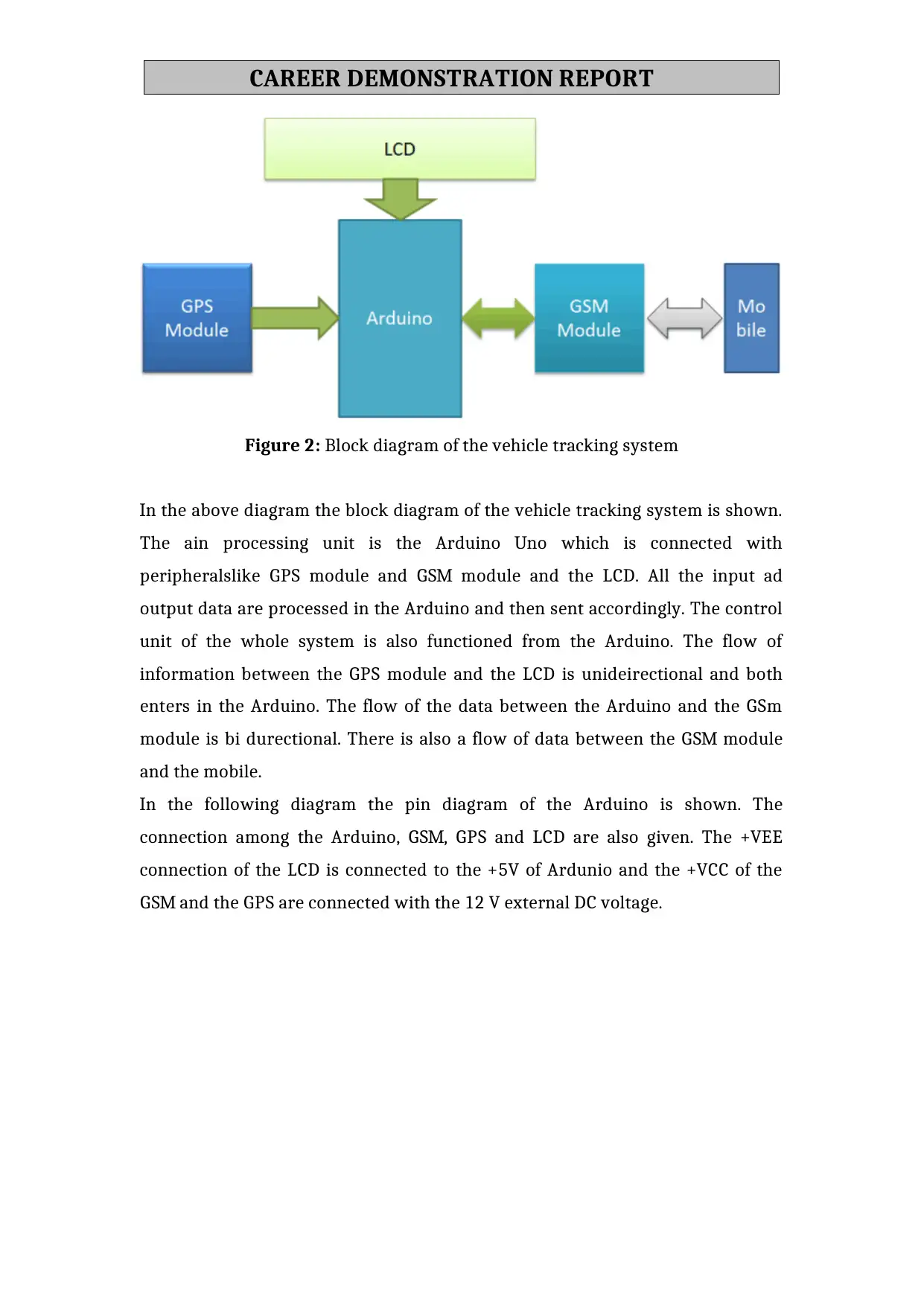
Figure 2: Block diagram of the vehicle tracking system
In the above diagram the block diagram of the vehicle tracking system is shown.
The ain processing unit is the Arduino Uno which is connected with
peripheralslike GPS module and GSM module and the LCD. All the input ad
output data are processed in the Arduino and then sent accordingly. The control
unit of the whole system is also functioned from the Arduino. The flow of
information between the GPS module and the LCD is unideirectional and both
enters in the Arduino. The flow of the data between the Arduino and the GSm
module is bi durectional. There is also a flow of data between the GSM module
and the mobile.
In the following diagram the pin diagram of the Arduino is shown. The
connection among the Arduino, GSM, GPS and LCD are also given. The +VEE
connection of the LCD is connected to the +5V of Ardunio and the +VCC of the
GSM and the GPS are connected with the 12 V external DC voltage.
CAREER DEMONSTRATION REPORT
Paraphrase This Document
Need a fresh take? Get an instant paraphrase of this document with our AI Paraphraser
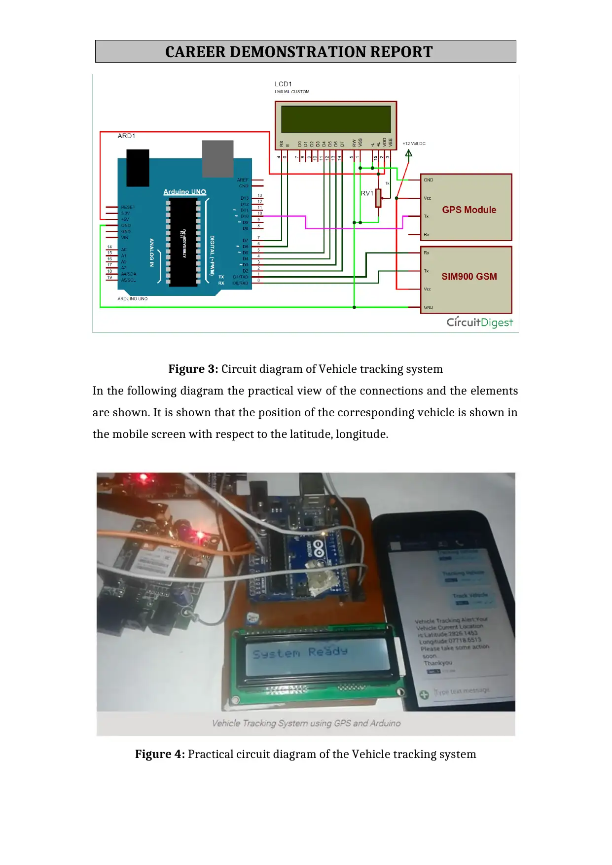
Figure 3: Circuit diagram of Vehicle tracking system
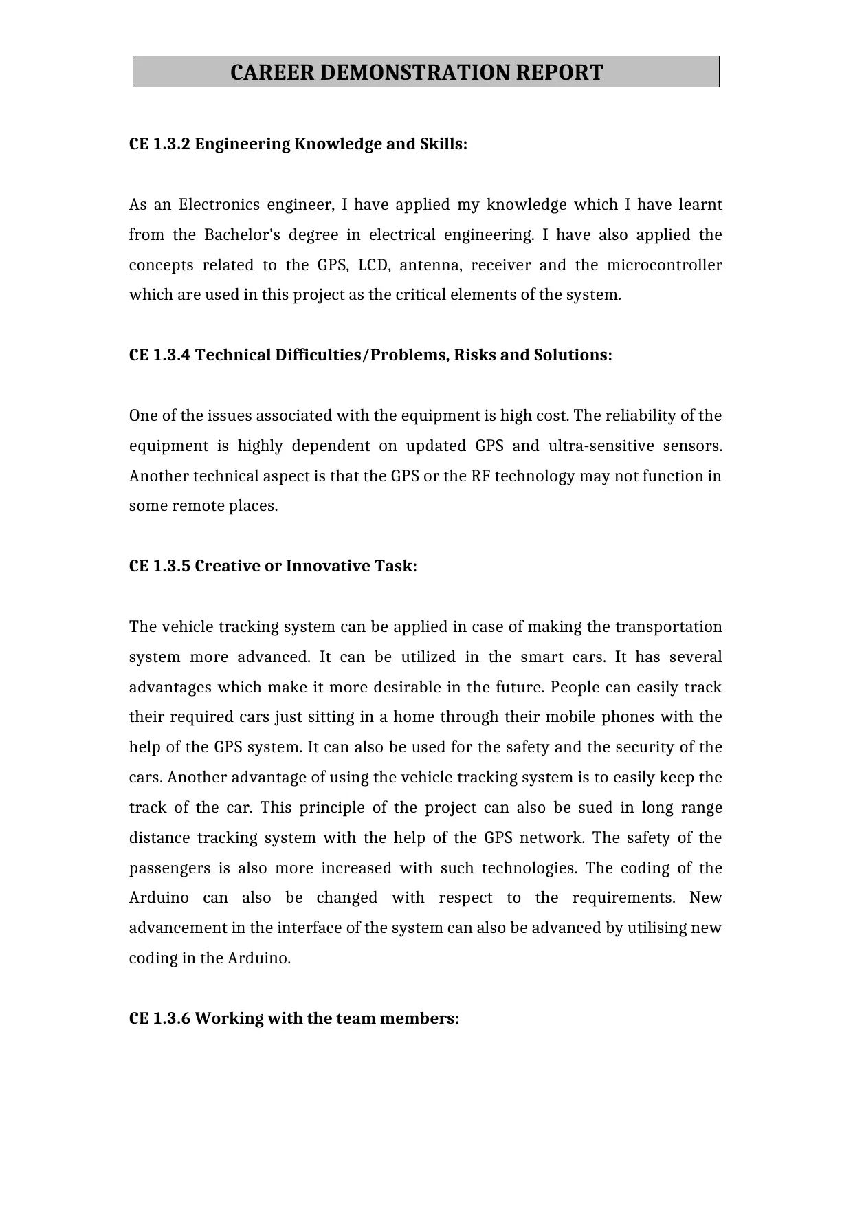
In the following diagram the practical view of the connections and the elements
are shown. It is shown that the position of the corresponding vehicle is shown in
the mobile screen with respect to the latitude, longitude.
Figure 4: Practical circuit diagram of the Vehicle tracking system
CAREER DEMONSTRATION REPORT
CE 1.3.2 Engineering Knowledge and Skills:
As an Electronics engineer, I have applied my knowledge which I have learnt
from the Bachelor's degree in electrical engineering. I have also applied the
concepts related to the GPS, LCD, antenna, receiver and the microcontroller
which are used in this project as the critical elements of the system.
CE 1.3.4 Technical Difficulties/Problems, Risks and Solutions:
One of the issues associated with the equipment is high cost. The reliability of the
equipment is highly dependent on updated GPS and ultra-sensitive sensors.
Another technical aspect is that the GPS or the RF technology may not function in
some remote places.
CE 1.3.5 Creative or Innovative Task:
The vehicle tracking system can be applied in case of making the transportation
system more advanced. It can be utilized in the smart cars. It has several
advantages which make it more desirable in the future. People can easily track
their required cars just sitting in a home through their mobile phones with the
help of the GPS system. It can also be used for the safety and the security of the
cars. Another advantage of using the vehicle tracking system is to easily keep the
track of the car. This principle of the project can also be sued in long range
distance tracking system with the help of the GPS network. The safety of the
passengers is also more increased with such technologies. The coding of the
Arduino can also be changed with respect to the requirements. New
advancement in the interface of the system can also be advanced by utilising new
coding in the Arduino.
CE 1.3.6 Working with the team members:
CAREER DEMONSTRATION REPORT
⊘ This is a preview!⊘
Do you want full access?
Subscribe today to unlock all pages.

Trusted by 1+ million students worldwide
I am thankful to my team members for their throughout support during the
project. We worked together to draft the outline of the entire plan and mutually
distributed various tasks in the project. I learned the sense of cooperation and
cumulative progress working in the team.
CE 1.4 Summary
CE 1.4.1 Project Overview:
I have created the project based on the vehicle tracking system. This project
requires the elements like Arduno UNO, GPS, GSM, LCD screen and the mobile.
The main processing unit of the system is designed in the ARduino and it also
sends the control signal to the other devices. The GPS and the GSM devices are
connected in order to get the signal regarding the global tracking system and to
send the data to the mobile phone using those mechanism. The Arduino is coded
in c language in order to create the instructions whichh are based on the
functioning of the whole system. This system is used successfully in order to
increase the security and the tracking system of the vehiclesis also advanced to a
large extent .
CE 1.4.2.My contribution to the project in meeting the goals
In this project I have applied my knowledge to make a vehicle tracking system. I
have designed and created all the connection which are drawn among the
Arduino and the GSM, GPS, LCD and the Mobile. The main idea of making the
system is to create the system more advanced in terms of increasing the security
and the tracking system of the vehicles are also taken into a new dimension with
the introduction of the technology in future. I have collected all the information
from different sources like internet and educational resources. I have created the
documentation of the project and submitted to the university.
CAREER DEMONSTRATION REPORT
1 out of 7
Related Documents
Your All-in-One AI-Powered Toolkit for Academic Success.
+13062052269
info@desklib.com
Available 24*7 on WhatsApp / Email
![[object Object]](/_next/static/media/star-bottom.7253800d.svg)
Unlock your academic potential
Copyright © 2020–2026 A2Z Services. All Rights Reserved. Developed and managed by ZUCOL.


