Electrotechnology Project: Water Level Controller System - 2017
VerifiedAdded on 2020/02/24
|9
|1278
|758
Project
AI Summary
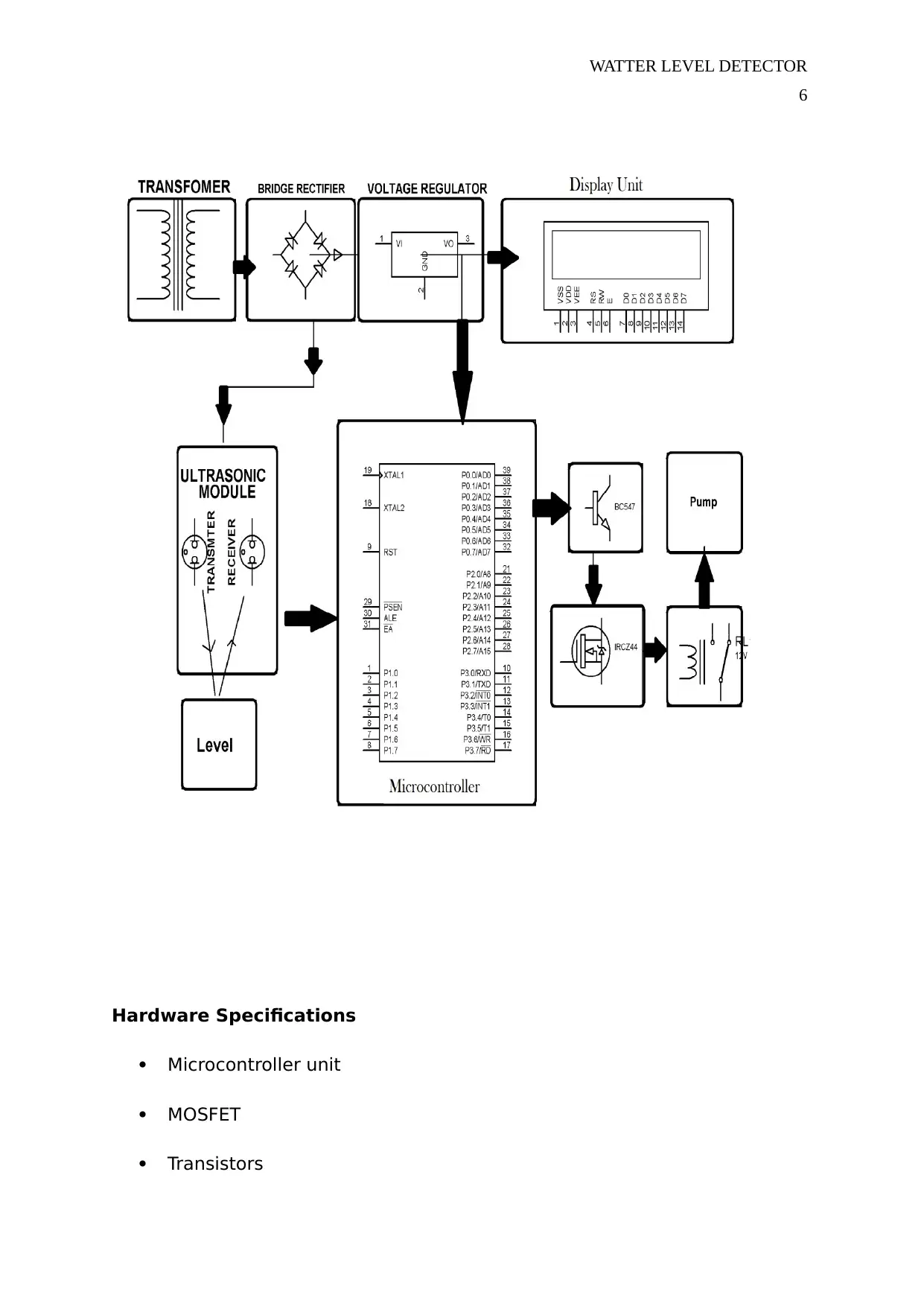
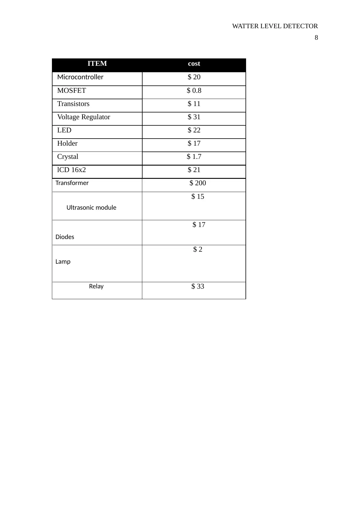
This project proposal outlines the design and implementation of a water level controller system using an ultrasonic module and a microcontroller. The system aims to automatically manage water levels in a tank by detecting the liquid level via ultrasonic signals, which are then processed by a microcontroller to control a pump. The project utilizes components such as an ultrasonic module, microcontroller, MOSFET, transistors, voltage regulator, and other electrical components. The system's operation is described in three conditions: tank empty, intermediate levels, and tank full, with corresponding outputs displayed on a seven-segment display and a lamp. The proposal includes hardware and software specifications, a block diagram, and a list of references. The primary outcome is to build an automated water level indicator system that efficiently manages water levels and potentially detects fuel levels in vehicles.

Running head: WATER LEVEL DETECTOR
0
Water Level Controller System without Contact
Department of Electrotechnology
Project Proposal 2017
By:
00000000
Supervisor:
Dr. Suresh Palapati
0
Water Level Controller System without Contact
Department of Electrotechnology
Project Proposal 2017
By:
00000000
Supervisor:
Dr. Suresh Palapati
Paraphrase This Document
Need a fresh take? Get an instant paraphrase of this document with our AI Paraphraser

WATTER LEVEL DETECTOR
2
Introduction
The project is designed to detect the level of liquid by using an ultrasonic module. The ultrasonic
module measures the range of liquid level (in cm) by detecting the reflection coming ahead of it. If
the measure of the level falls below a set point the pump automatically starts (Bell, 2014). The
project uses a microcontroller whose serial port is interfaced with this ultrasonic module. The Tx
sensor sends the ultrasonic signal reflected from the level and is received by the ultrasonic Rx
sensor. These signals are then sent to a microcontroller that initiates the relay to switch the pump
on or off with the help of a MOSFET (Burt, 2013).
This ultrasonic level controller comprises of an ultrasonic module which detects precise range by
reflection coming ahead of it. This module is interfaced with the serial port of the microcontroller.
Whenever level distance measured by cm falls below a set point the pump starts since by sensing
the ultrasonic module signal coming out from the Tx sensor being reflected from the level and is
received by the ultrasonic Rx sensor the output of which is fed to the microcontroller (Chiah, 2013).
List of outcomes
The most significant outcome of this project is to build up water indicator
system. In order to achieve there are some steps, have to be done in order to get the
good outcomes for the project. This project will help to automatically manage water
level by the pump being started automatically by water but immediately the water
level goes lower than the prearranged level which is always half of the tank. And it

WATTER LEVEL DETECTOR
3
will turn OFF the pump immediately the tank is full. This design will also help in
detecting the level of fuel in the vehicles (Stanford, 2011).
Initial negotiation
In the beginning of the project, an initial negotiated with the project supervisor for the
second semester 2017 Suresh
Designing and Building the actual model
On this project we will be able to build a model which will help in control the level of
water in a given container. A constant of the 5V power supply is obtained from the
transformer which is then connected to a bridge rectifier which changes the AC to Dc and
then a voltage regulator is connected to ensure a constant DC of 5V is maintained (Chiah,
2013). The tank to which the sensor is put is connected to the 5V DC power supply and 8
wires of the sensors of which one wire is connected to the constant 5 V DC supply while
others are connected to the transistors. There is the usage of the transistors in this project
is very important as itoperates as an inverter, for instance, in ON mode it gives a low
voltage at the output when in OFF mode it will give high voltage at its output. All the
output of the transistor is connected to the PORT of the Atmega 328 Microcontroller
(Stanford, 2011). Out of the 8th level (tank full condition) is not displayed in the seven
section display only but also shown with a nonstop lamb which helps to give the indication.
This is clearly indicated in the block diagram below.
⊘ This is a preview!⊘
Do you want full access?
Subscribe today to unlock all pages.

Trusted by 1+ million students worldwide

WATTER LEVEL DETECTOR
4
Connecting and Testing
Fixing the electrical apparatuses like the microcontrollers, sensors and wires into the
system and immediately this is done then the system is tested. The operation of the
project is very easy to understand on the three condition operation of the sensor.
Condition 1: Water not available
If the water tank has no water there will be lack of path between the designating
probes which are eight for this case and the other probe which is coupled to the +5V supply
such that the base emitter region of the transistor wont have enough biasing voltage thus it
rests in a cutoff region and the output on its collector will be roughly 4.2V. And for Atmega
328 Microcontroller, it employs the active low region ( 0-2 voltage for HIGH and about 3-5
voltage for LOW). Therefore the output of the transistor which will be 4.2 V is now
considered LOW by Atmega 328 Microcontroller and a default value is given to Atmega 328
Microcontroller the seven segment which displays 0 indicating that the tank has no water
(Burt, 2013).
Condition 2: Intermediate levels
If the water begins to fill the tank a pathway is recognized amid the sensor probe
and the corresponding transistors gets enough biasing at the base of the transistor, they
begin to conduct an d now the output will be about VCe ( 1.2-1.8) and this is given by
Atmega 328 Microcontroller. This microcontroller is set as an encoder of priority which
helps to detect the maximum priority input and shows consistent level of in the seven 7
sector display. The water level for this condition will be in the 7th level then a discontinuous
lamp will be activated which informs the operator that the tank will not be filled soon
(Stanford, 2011).
Condition 3: Water full
If the tank is made full, the top of the probe obtains the pathway via water and the
equivalent to transistor will get into pathway where the output set to the Atmega 328
Microcontroller with the input microcontroller not only shows the level in the seven section
Paraphrase This Document
Need a fresh take? Get an instant paraphrase of this document with our AI Paraphraser

WATTER LEVEL DETECTOR
5
but also it triggers the nonstop lamp where the operator can fathom that the tank is
occupied and then turn OFF the motor and saves water. This will indicate that the water is
full in the water tank (Bell, 2014).
Preparing reports and presentation
A progress presentation will be given on time.
A final written report will be provided later on.
An oral presentation and demonstration for the final product will take a place at the end of
this semester.
Block Diagram:

WATTER LEVEL DETECTOR
6
Hardware Specifications
Microcontroller unit
MOSFET
Transistors
6
Hardware Specifications
Microcontroller unit
MOSFET
Transistors
⊘ This is a preview!⊘
Do you want full access?
Subscribe today to unlock all pages.

Trusted by 1+ million students worldwide

WATTER LEVEL DETECTOR
7
Voltage Regulator
LED
Holder
Crystal
LCD (16×2)
Transformer
Ultrasonic module
Diodes
Lamp
Relay
Software Specifications
Arduino compiler
MC Programming Language: Embedded C
7
Voltage Regulator
LED
Holder
Crystal
LCD (16×2)
Transformer
Ultrasonic module
Diodes
Lamp
Relay
Software Specifications
Arduino compiler
MC Programming Language: Embedded C
Paraphrase This Document
Need a fresh take? Get an instant paraphrase of this document with our AI Paraphraser

WATTER LEVEL DETECTOR
8
ITEM cost
Microcontroller $ 20
MOSFET $ 0.8
Transistors $ 11
Voltage Regulator $ 31
LED $ 22
Holder $ 17
Crystal $ 1.7
lCD 16x2 $ 21
Transformer $ 200
Ultrasonic module
$ 15
Diodes
$ 17
Lamp
$ 2
Relay $ 33
8
ITEM cost
Microcontroller $ 20
MOSFET $ 0.8
Transistors $ 11
Voltage Regulator $ 31
LED $ 22
Holder $ 17
Crystal $ 1.7
lCD 16x2 $ 21
Transformer $ 200
Ultrasonic module
$ 15
Diodes
$ 17
Lamp
$ 2
Relay $ 33

WATTER LEVEL DETECTOR
9
References
Bell, C. (2014). Behinning Sensor Network . Manchester : Apress.
Burt, A. G. (2013). Water Level Sensor and Datalonger Testring and demostration. Washington :
ITRC.
Chiah, Y. H. (2013). The development of capacitive Water Level Sensor . Malaysia : University of
Malaysia .
Stanford, H. W. (2011). HVAC Water Chillers and cooling Tower . Hull: CRC.
⊘ This is a preview!⊘
Do you want full access?
Subscribe today to unlock all pages.

Trusted by 1+ million students worldwide
1 out of 9

Your All-in-One AI-Powered Toolkit for Academic Success.
+13062052269
info@desklib.com
Available 24*7 on WhatsApp / Email
Unlock your academic potential
Copyright © 2020–2025 A2Z Services. All Rights Reserved. Developed and managed by ZUCOL.