Civil Engineering Project: Embankment Dam and Slope Stability

Verified

Added on  2019/09/22

|8
|523
|273
Project
AI Summary
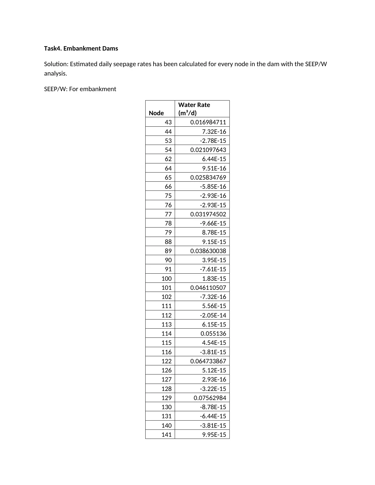
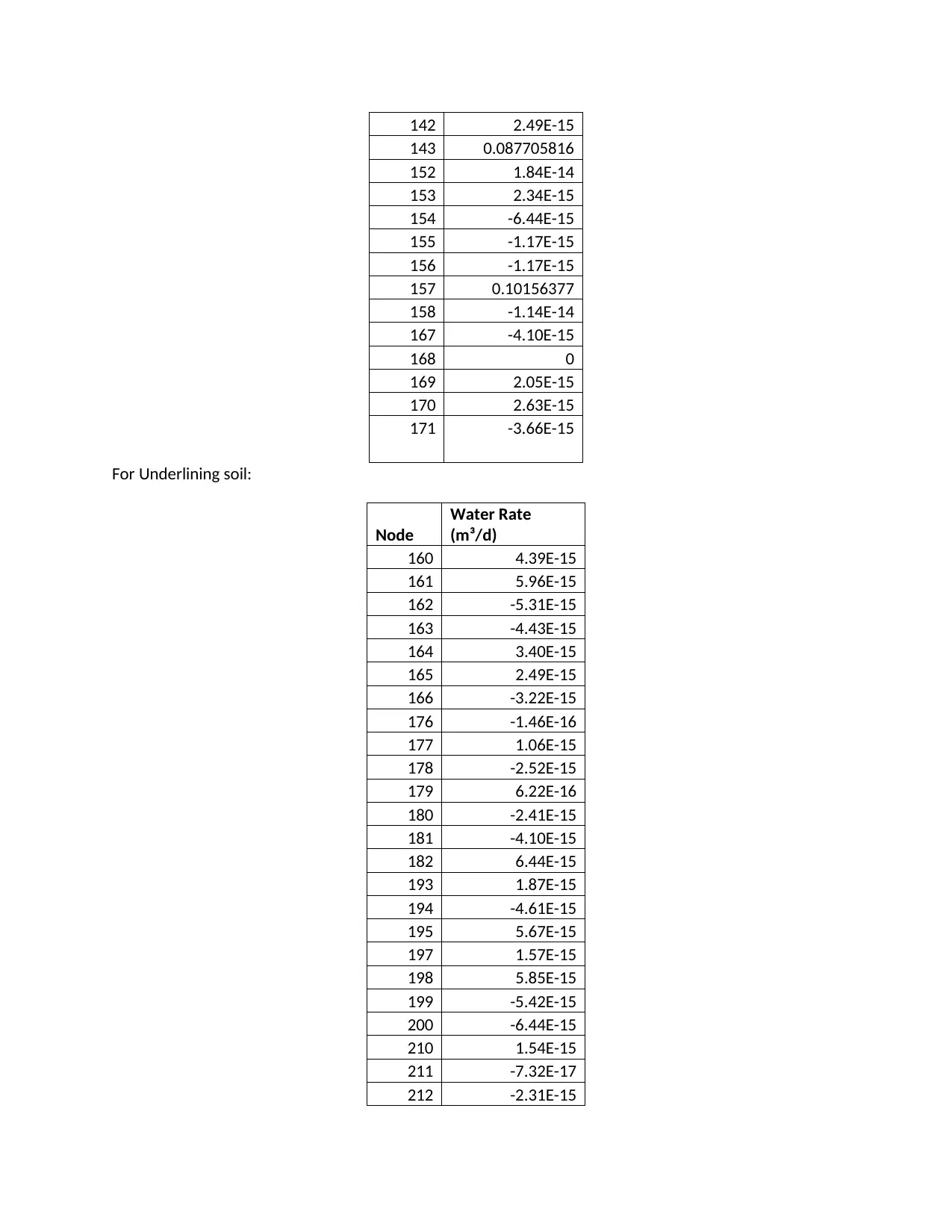
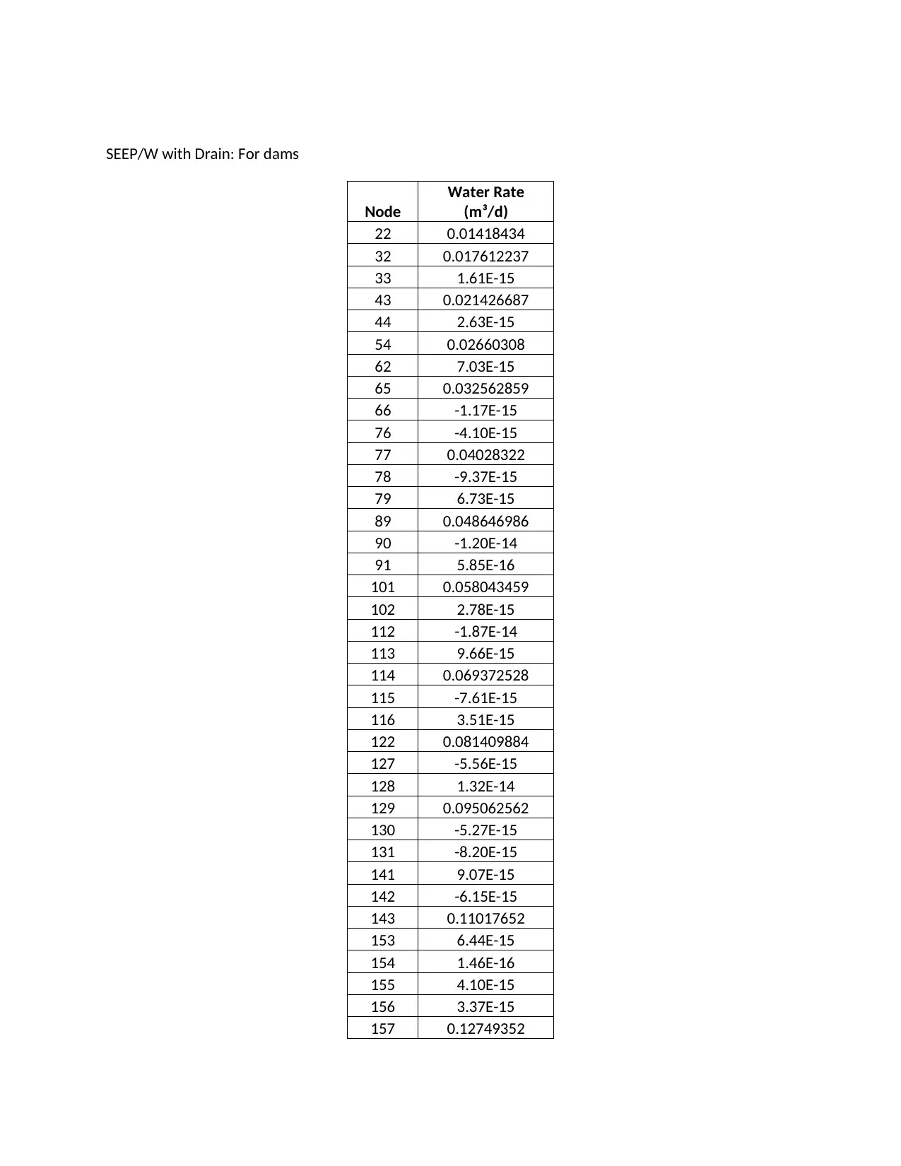
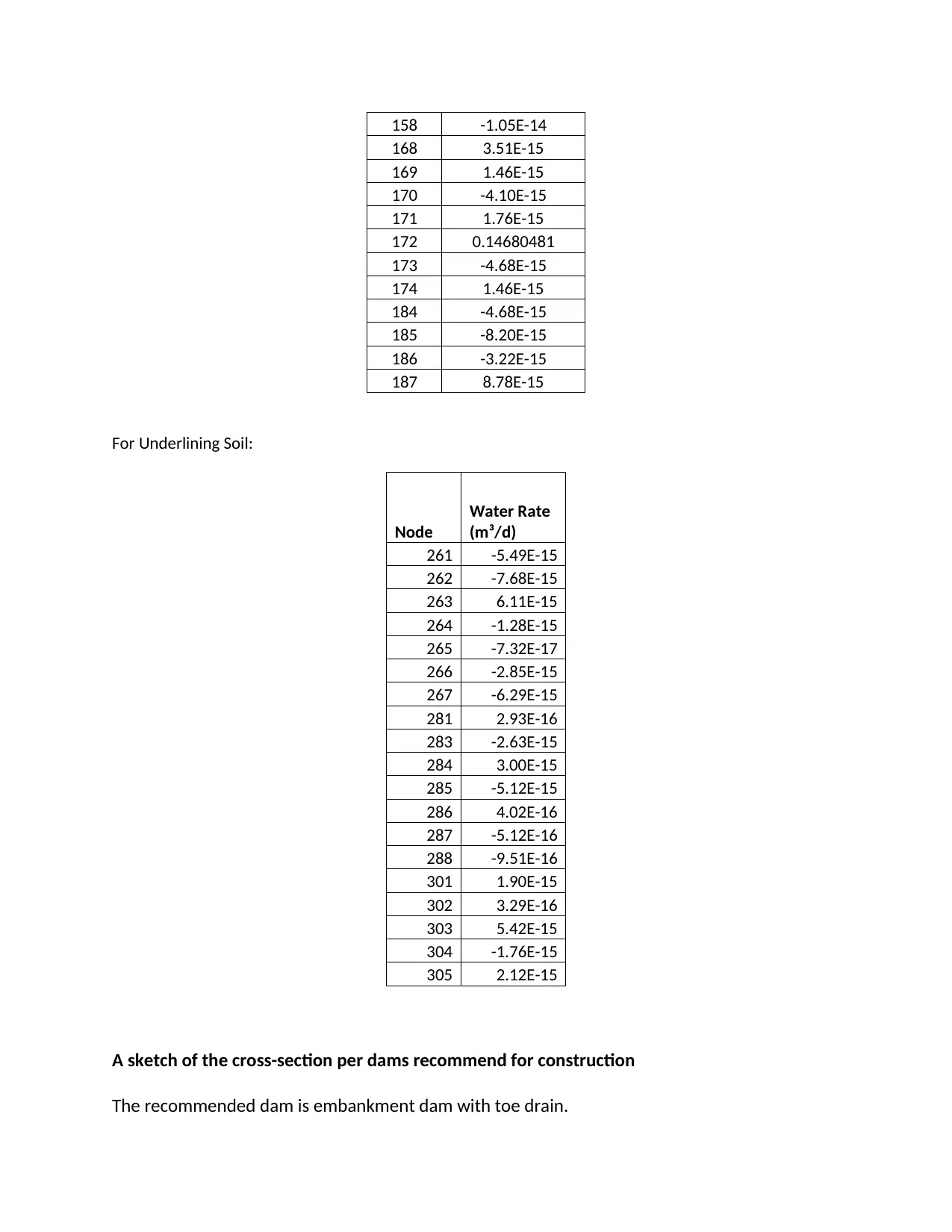
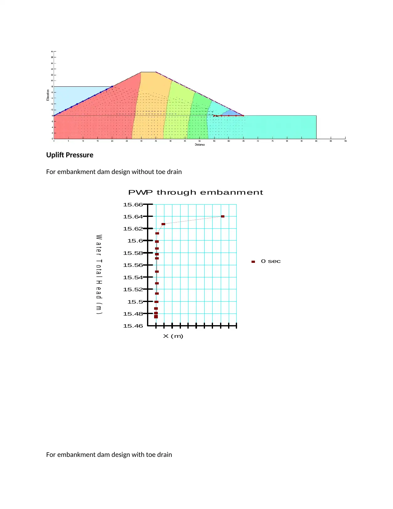
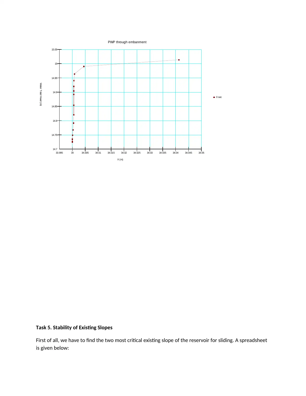
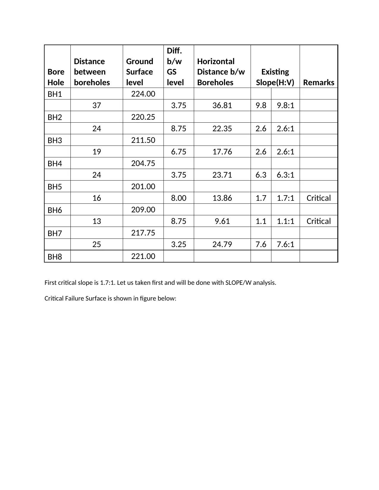
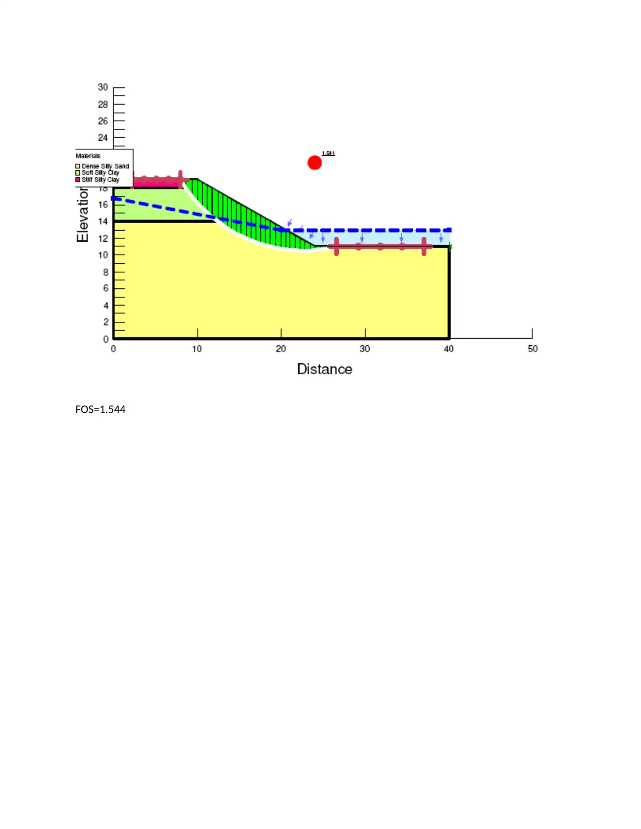
This document presents a comprehensive solution for an embankment dam design and slope stability project. The solution begins with a detailed seepage analysis for the dam, calculating daily seepage rates for various nodes within the embankment and underlying soil using SEEP/W software. Different dam configurations, including those with and without a toe drain, are considered, and uplift pressures are evaluated. Subsequently, the project focuses on the stability of existing slopes within a reservoir, identifying critical slopes based on borehole data and slope calculations. The SLOPE/W analysis is then performed to assess the stability of the most critical slope, determining the factor of safety and identifying the critical failure surface. The project integrates both seepage and stability considerations, offering a complete overview of embankment dam design principles and analysis techniques.
tabler-icon-diamond-filled.svg

Contribute Materials

Your contribution can guide someone’s learning journey. Share your documents today.
Document Page
Task4. Embankment Dams
Solution: Estimated daily seepage rates has been calculated for every node in the dam with the SEEP/W
analysis.
SEEP/W: For embankment
Node
Water Rate
(m³/d)
43 0.016984711
44 7.32E-16
53 -2.78E-15
54 0.021097643
62 6.44E-15
64 9.51E-16
65 0.025834769
66 -5.85E-16
75 -2.93E-16
76 -2.93E-15
77 0.031974502
78 -9.66E-15
79 8.78E-15
88 9.15E-15
89 0.038630038
90 3.95E-15
91 -7.61E-15
100 1.83E-15
101 0.046110507
102 -7.32E-16
111 5.56E-15
112 -2.05E-14
113 6.15E-15
114 0.055136
115 4.54E-15
116 -3.81E-15
122 0.064733867
126 5.12E-15
127 2.93E-16
128 -3.22E-15
129 0.07562984
130 -8.78E-15
131 -6.44E-15
140 -3.81E-15
141 9.95E-15
tabler-icon-diamond-filled.svg

Secure Best Marks with AI Grader

Need help grading? Try our AI Grader for instant feedback on your assignments.
Document Page
142 2.49E-15
143 0.087705816
152 1.84E-14
153 2.34E-15
154 -6.44E-15
155 -1.17E-15
156 -1.17E-15
157 0.10156377
158 -1.14E-14
167 -4.10E-15
168 0
169 2.05E-15
170 2.63E-15
171 -3.66E-15
For Underlining soil:
Node
Water Rate
(m³/d)
160 4.39E-15
161 5.96E-15
162 -5.31E-15
163 -4.43E-15
164 3.40E-15
165 2.49E-15
166 -3.22E-15
176 -1.46E-16
177 1.06E-15
178 -2.52E-15
179 6.22E-16
180 -2.41E-15
181 -4.10E-15
182 6.44E-15
193 1.87E-15
194 -4.61E-15
195 5.67E-15
197 1.57E-15
198 5.85E-15
199 -5.42E-15
200 -6.44E-15
210 1.54E-15
211 -7.32E-17
212 -2.31E-15
Document Page
SEEP/W with Drain: For dams
Node
Water Rate
(m³/d)
22 0.01418434
32 0.017612237
33 1.61E-15
43 0.021426687
44 2.63E-15
54 0.02660308
62 7.03E-15
65 0.032562859
66 -1.17E-15
76 -4.10E-15
77 0.04028322
78 -9.37E-15
79 6.73E-15
89 0.048646986
90 -1.20E-14
91 5.85E-16
101 0.058043459
102 2.78E-15
112 -1.87E-14
113 9.66E-15
114 0.069372528
115 -7.61E-15
116 3.51E-15
122 0.081409884
127 -5.56E-15
128 1.32E-14
129 0.095062562
130 -5.27E-15
131 -8.20E-15
141 9.07E-15
142 -6.15E-15
143 0.11017652
153 6.44E-15
154 1.46E-16
155 4.10E-15
156 3.37E-15
157 0.12749352
Document Page
158 -1.05E-14
168 3.51E-15
169 1.46E-15
170 -4.10E-15
171 1.76E-15
172 0.14680481
173 -4.68E-15
174 1.46E-15
184 -4.68E-15
185 -8.20E-15
186 -3.22E-15
187 8.78E-15
For Underlining Soil:
Node
Water Rate
(m³/d)
261 -5.49E-15
262 -7.68E-15
263 6.11E-15
264 -1.28E-15
265 -7.32E-17
266 -2.85E-15
267 -6.29E-15
281 2.93E-16
283 -2.63E-15
284 3.00E-15
285 -5.12E-15
286 4.02E-16
287 -5.12E-16
288 -9.51E-16
301 1.90E-15
302 3.29E-16
303 5.42E-15
304 -1.76E-15
305 2.12E-15
A sketch of the cross-section per dams recommend for construction
The recommended dam is embankment dam with toe drain.
tabler-icon-diamond-filled.svg

Secure Best Marks with AI Grader

Need help grading? Try our AI Grader for instant feedback on your assignments.
Document Page
Uplift Pressure
For embankment dam design without toe drain
PWP through embanment
0 sec
W a t e r T o t a l H e a d ( m )
X (m)
15.46
15.48
15.5
15.52
15.54
15.56
15.58
15.6
15.62
15.64
15.66
For embankment dam design with toe drain
Document Page
PWP through embanment
0 sec
Water Total Head (m)
X (m)
14.7
14.75
14.8
14.85
14.9
14.95
15
15.05
33.995 34 34.005 34.01 34.015 34.02 34.025 34.03 34.035 34.04 34.045 34.05
Task 5. Stability of Existing Slopes
First of all, we have to find the two most critical existing slope of the reservoir for sliding. A spreadsheet
is given below:
Document Page
Bore
Hole
Distance
between
boreholes
Ground
Surface
level
Diff.
b/w
GS
level
Horizontal
Distance b/w
Boreholes
Existing
Slope(H:V) Remarks
BH1 224.00
37 3.75 36.81 9.8 9.8:1
BH2 220.25
24 8.75 22.35 2.6 2.6:1
BH3 211.50
19 6.75 17.76 2.6 2.6:1
BH4 204.75
24 3.75 23.71 6.3 6.3:1
BH5 201.00
16 8.00 13.86 1.7 1.7:1 Critical
BH6 209.00
13 8.75 9.61 1.1 1.1:1 Critical
BH7 217.75
25 3.25 24.79 7.6 7.6:1
BH8 221.00
First critical slope is 1.7:1. Let us taken first and will be done with SLOPE/W analysis.
Critical Failure Surface is shown in figure below:
tabler-icon-diamond-filled.svg

Paraphrase This Document

Need a fresh take? Get an instant paraphrase of this document with our AI Paraphraser
Document Page
FOS=1.544
chevron_up_icon
1 out of 8
circle_padding
hide_on_mobile
zoom_out_icon
logo.png

Your All-in-One AI-Powered Toolkit for Academic Success.

Available 24*7 on WhatsApp / Email

[object Object]