Embedded System - Microcontroller Programming, Interrupts, and I/O

Verified

Added on  2020/04/29

|7
|876
|64
Homework Assignment
AI Summary
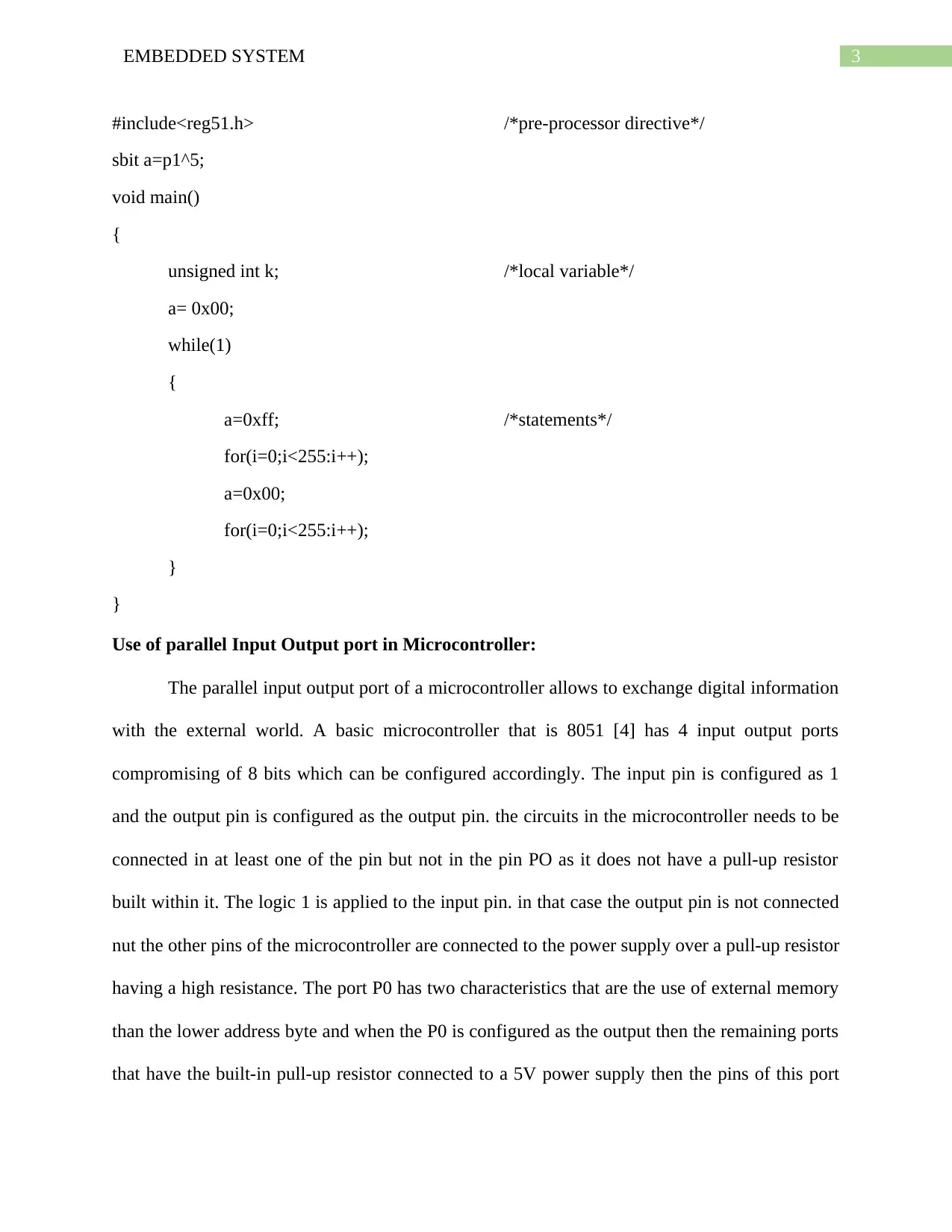
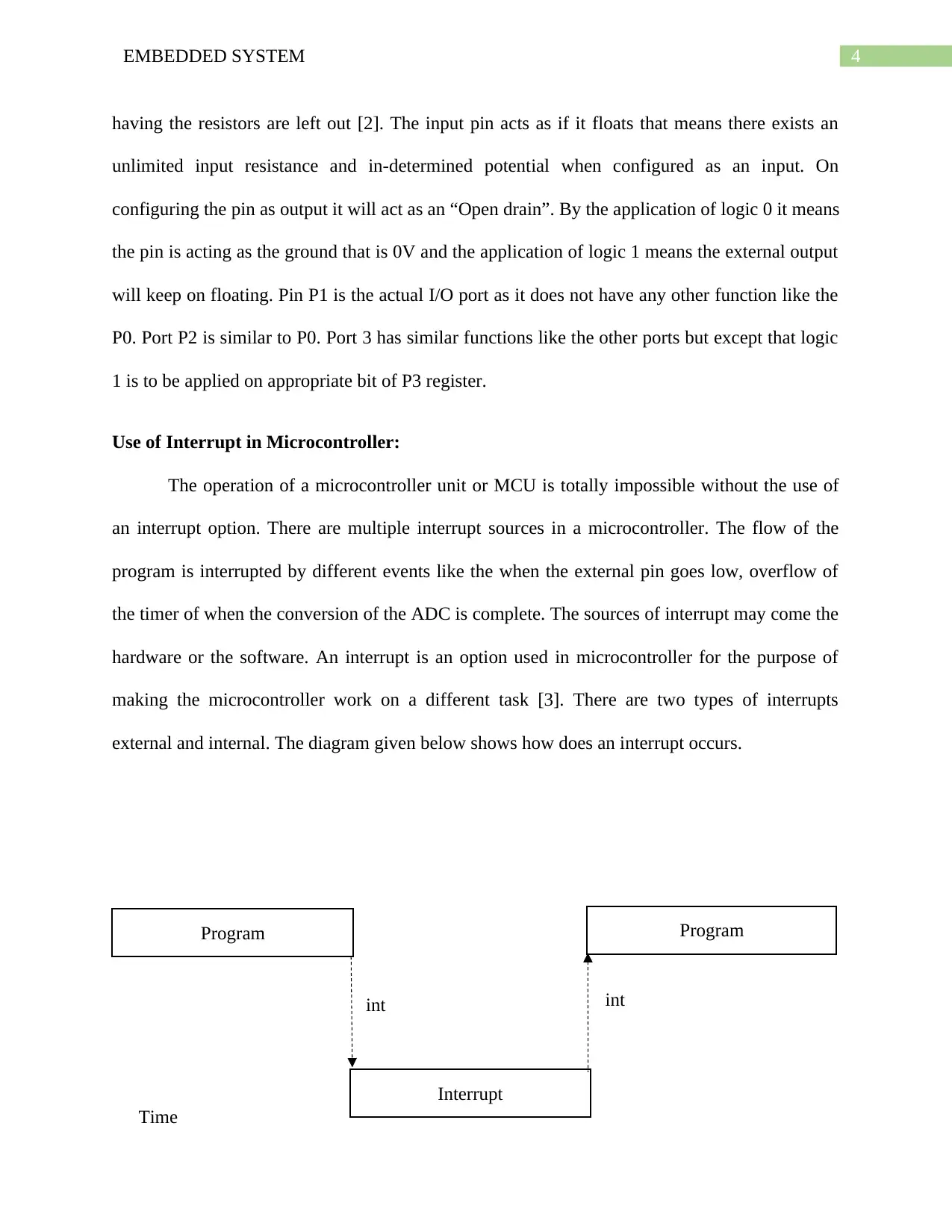
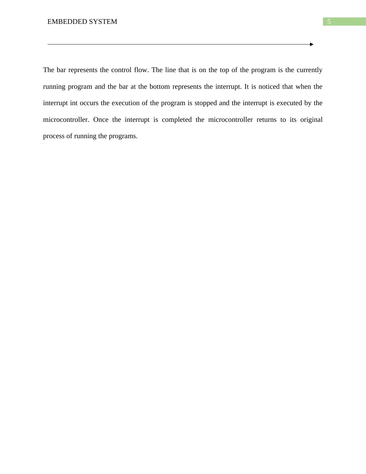
This document presents a solution to an embedded systems assignment focusing on microcontroller programming using C. It begins with an overview of the basic C programming structure used in microcontrollers and provides a simple C program example for toggling an 8051 microcontroller's output pin. The assignment then delves into the use of parallel input/output (I/O) ports, explaining their configuration and functionality, including the behavior of different port pins and the role of pull-up resistors. Finally, the solution explores the concept of interrupts in microcontrollers, detailing their importance, the different types of interrupts (external and internal), and how interrupts affect the program execution flow, including a diagram illustrating the interrupt process. The document concludes with a list of relevant references.
Document Page
Running head: EMBEDDED SYSTEM
Embedded System
Name of the Student
Name of the University
Author note
tabler-icon-diamond-filled.svg

Paraphrase This Document

Need a fresh take? Get an instant paraphrase of this document with our AI Paraphraser
Document Page
1EMBEDDED SYSTEM
Table of Contents
C Programming in a Microcontroller:.............................................................................................2
Use of parallel Input Output port in Microcontroller:.....................................................................3
Use of Interrupt in Microcontroller:................................................................................................4
References:......................................................................................................................................6
Document Page
2EMBEDDED SYSTEM
Microcontroller is nothing but a small computer on an integrated circuit. Microcontroller
consists of one or more CPUs along with a memory and input output port that can be
programmed accordingly [1].
C Programming in a Microcontroller:
The common C programming structure of a microcontroller is given below;
Comments
preprocessor directives
global variables
main() function
{
local variables
statements
…………..
…………..
}
fun(1)
{
local variables
statements
…………..
…………..
}
A simple c programing that is used for toggling of an 8051 microcontroller is given
below:
Document Page
3EMBEDDED SYSTEM
#include<reg51.h> /*pre-processor directive*/
sbit a=p1^5;
void main()
{
unsigned int k; /*local variable*/
a= 0x00;
while(1)
{
a=0xff; /*statements*/
for(i=0;i<255:i++);
a=0x00;
for(i=0;i<255:i++);
}
}
Use of parallel Input Output port in Microcontroller:
The parallel input output port of a microcontroller allows to exchange digital information
with the external world. A basic microcontroller that is 8051 [4] has 4 input output ports
compromising of 8 bits which can be configured accordingly. The input pin is configured as 1
and the output pin is configured as the output pin. the circuits in the microcontroller needs to be
connected in at least one of the pin but not in the pin PO as it does not have a pull-up resistor
built within it. The logic 1 is applied to the input pin. in that case the output pin is not connected
nut the other pins of the microcontroller are connected to the power supply over a pull-up resistor
having a high resistance. The port P0 has two characteristics that are the use of external memory
than the lower address byte and when the P0 is configured as the output then the remaining ports
that have the built-in pull-up resistor connected to a 5V power supply then the pins of this port
tabler-icon-diamond-filled.svg

Paraphrase This Document

Need a fresh take? Get an instant paraphrase of this document with our AI Paraphraser
Document Page
4EMBEDDED SYSTEM
having the resistors are left out [2]. The input pin acts as if it floats that means there exists an
unlimited input resistance and in-determined potential when configured as an input. On
configuring the pin as output it will act as an “Open drain”. By the application of logic 0 it means
the pin is acting as the ground that is 0V and the application of logic 1 means the external output
will keep on floating. Pin P1 is the actual I/O port as it does not have any other function like the
P0. Port P2 is similar to P0. Port 3 has similar functions like the other ports but except that logic
1 is to be applied on appropriate bit of P3 register.
Use of Interrupt in Microcontroller:
The operation of a microcontroller unit or MCU is totally impossible without the use of
an interrupt option. There are multiple interrupt sources in a microcontroller. The flow of the
program is interrupted by different events like the when the external pin goes low, overflow of
the timer of when the conversion of the ADC is complete. The sources of interrupt may come the
hardware or the software. An interrupt is an option used in microcontroller for the purpose of
making the microcontroller work on a different task [3]. There are two types of interrupts
external and internal. The diagram given below shows how does an interrupt occurs.
Program Program
Interrupt
int int
Time
Document Page
5EMBEDDED SYSTEM
The bar represents the control flow. The line that is on the top of the program is the currently
running program and the bar at the bottom represents the interrupt. It is noticed that when the
interrupt int occurs the execution of the program is stopped and the interrupt is executed by the
microcontroller. Once the interrupt is completed the microcontroller returns to its original
process of running the programs.
Document Page
6EMBEDDED SYSTEM
References:
1. Z. Hajduk, "An FPGA embedded microcontroller", Microprocessors and Microsystems, vol.
38, no. 1, pp. 1-8, 2014.
2. B. M.P., Interfacing PIC microcontrollers: Embedded design by interactive simulation. 2013.
3. E. Beckschulze, S. Biallas and S. Kowalewski, "Static Analysis of Lockless Microcontroller C
Programs", Electronic Proceedings in Theoretical Computer Science, vol. 102, pp. 103-114,
2012.
4. W. Mansour and R. Velazco, "An Automated SEU Fault-Injection Method and Tool for HDL-
Based Designs", IEEE Transactions on Nuclear Science, vol. 60, no. 4, pp. 2728-2733, 2013.
chevron_up_icon
1 out of 7
circle_padding
hide_on_mobile
zoom_out_icon
[object Object]