Employee Absence Management System
VerifiedAdded on 2019/09/16
|13
|965
|360
Project
AI Summary
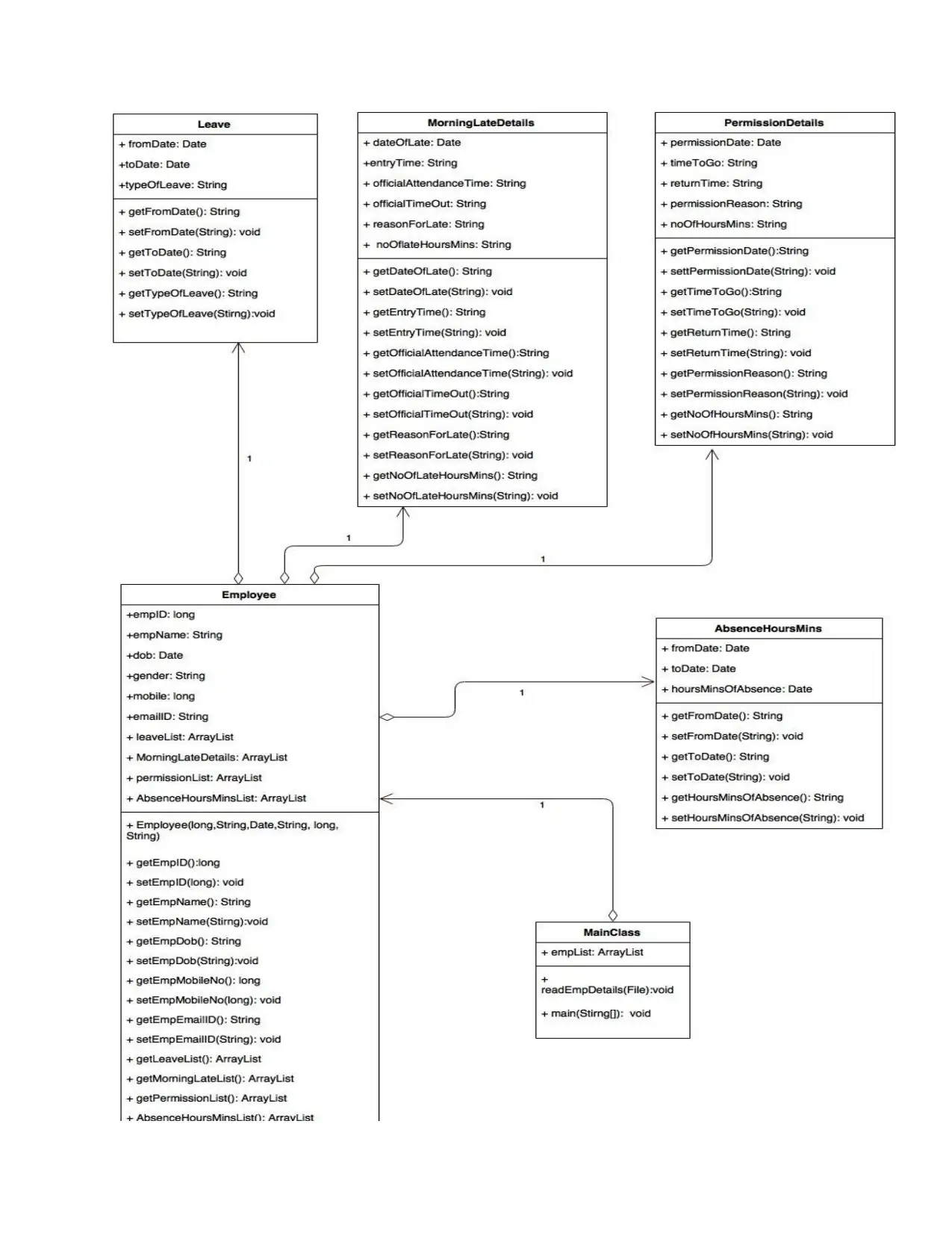
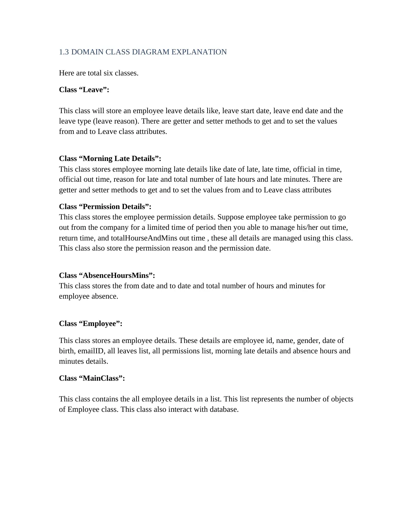
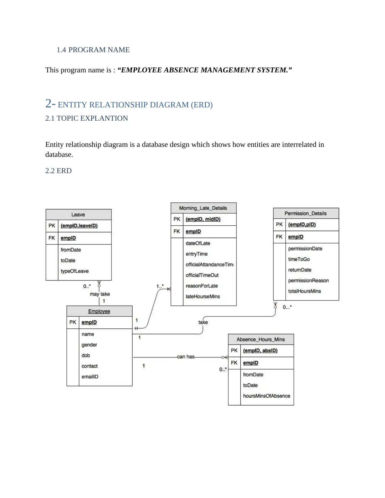
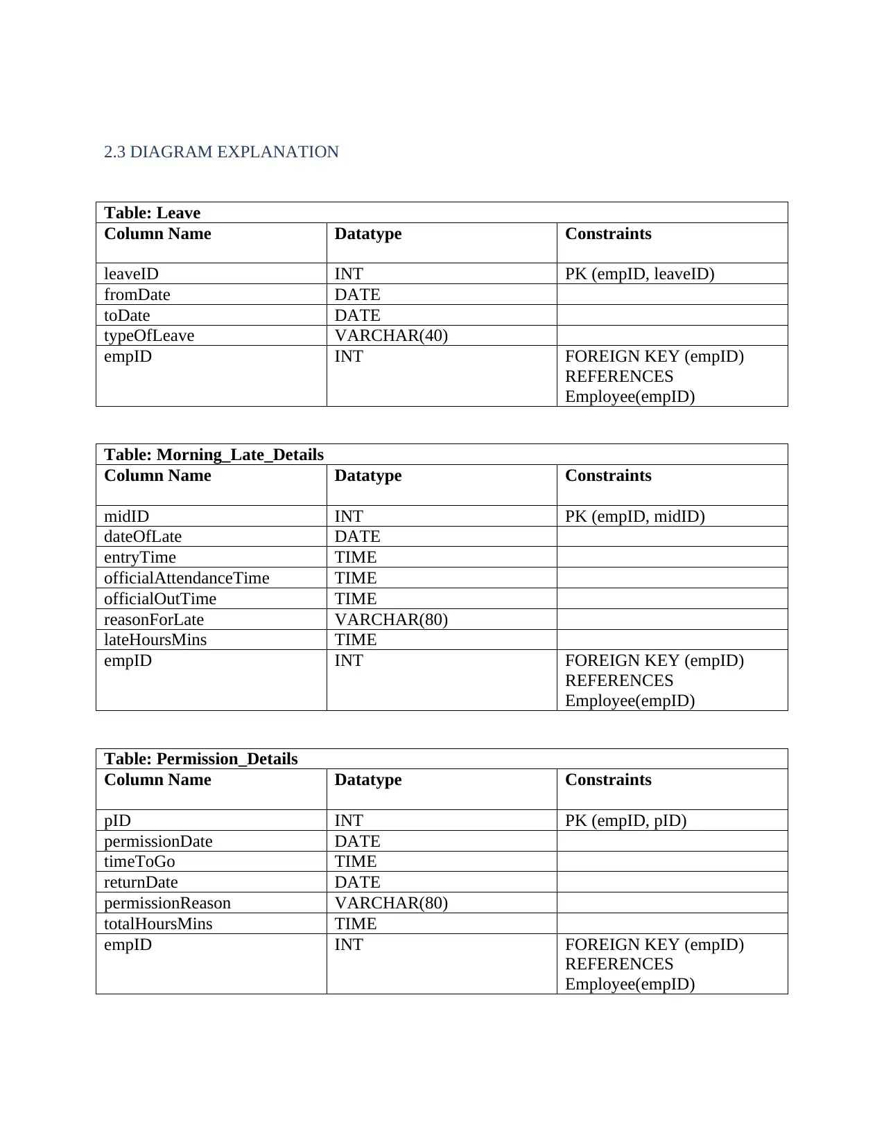
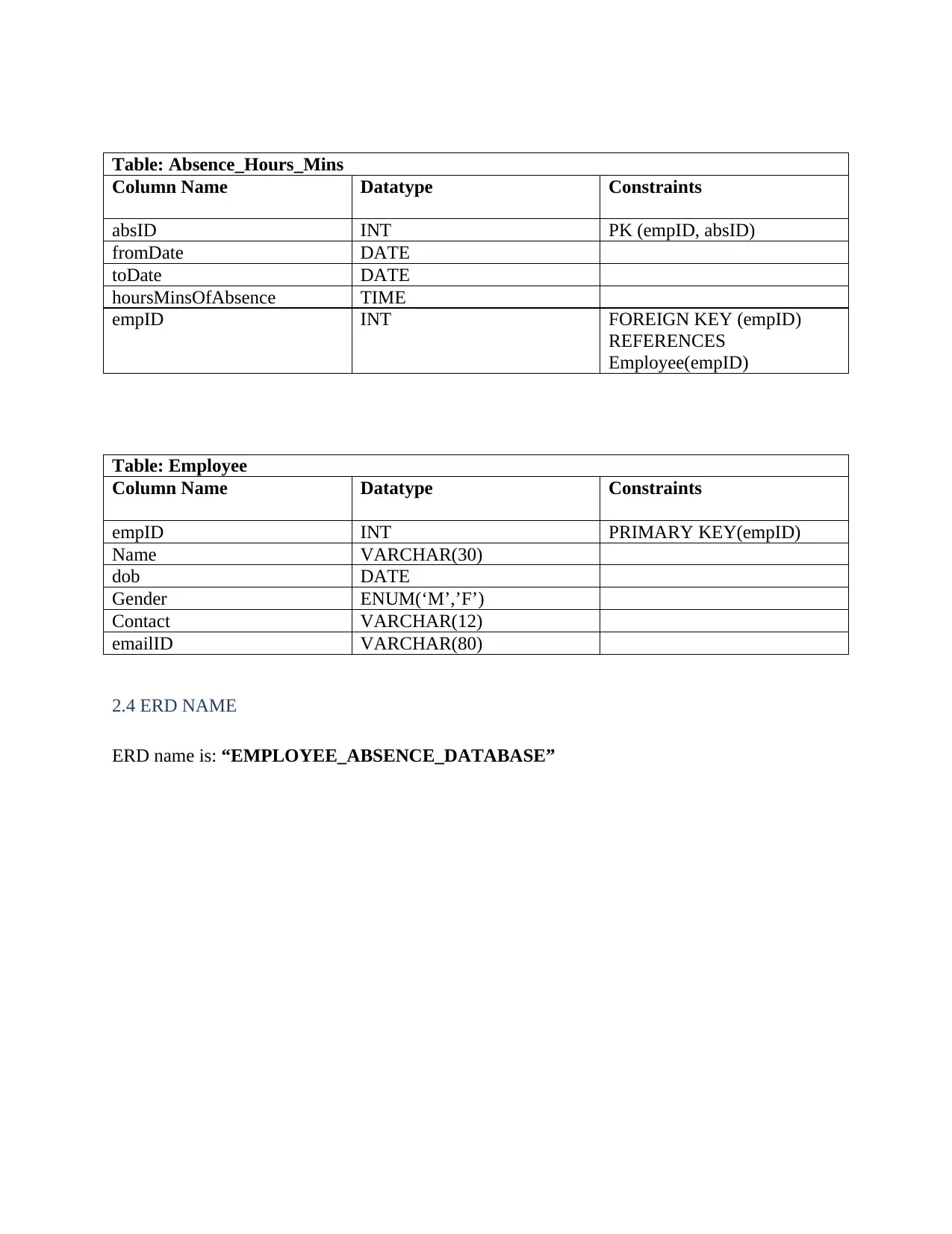
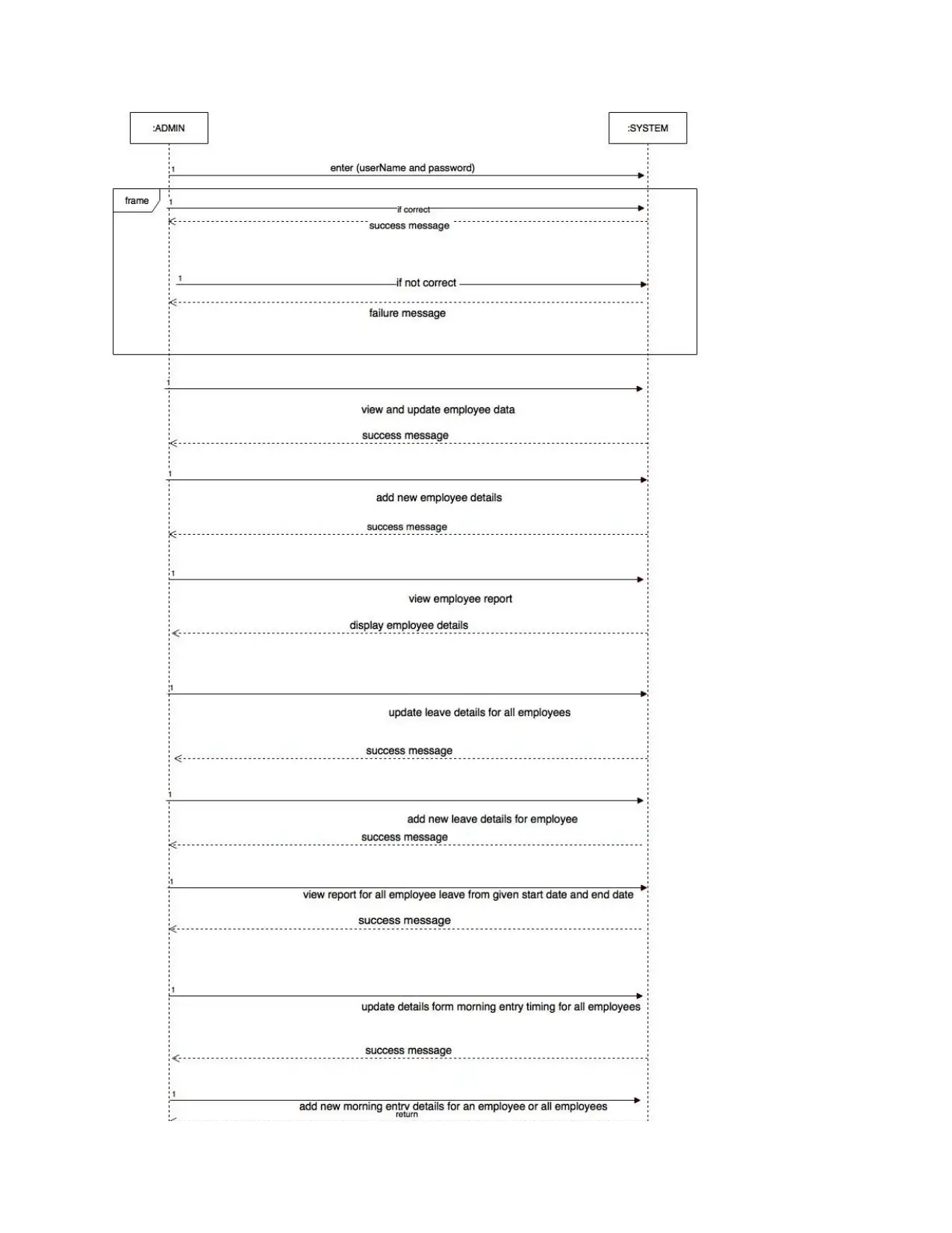
This project focuses on designing a database for an employee absence management system. The solution includes three key diagrams: a Domain Class Diagram (DCD), an Entity Relationship Diagram (ERD), and a System Sequence Diagram (SSD). The DCD illustrates the classes and their relationships, including 'Leave,' 'Morning Late Details,' 'Permission Details,' 'AbsenceHoursMins,' 'Employee,' and 'MainClass.' The ERD details the database schema, outlining tables such as 'Leave,' 'Morning_Late_Details,' 'Permission_Details,' 'Absence_Hours_Mins,' and 'Employee,' along with their columns, data types, and constraints. The SSD depicts the interaction flow between the admin and the system, showing the sequence of actions and system responses. The project also includes a detailed explanation of each diagram and its components, providing a comprehensive guide to database design for an employee absence management system. The project aims to manage employee leaves, time-in/out, permitted time, and absence hours, providing a better employee database for managers and supervisors.

Contents
TASKS:............................................................................................................................................2
1. DOMAIN CLASS DIAGRAM (DCD)................................................................................2
1.1 TOPIC EXPLANATION...................................................................................................2
1.2 DCD...................................................................................................................................4
1.3 DOMAIN CLASS DIAGRAM EXPLANATION........................................................6
1.4 PROGRAM NAME......................................................................................................7
2- ENTITY RELATIONSHIP DIAGRAM (ERD).....................................................................7
2.1 TOPIC EXPLANTION.....................................................................................................7
2.2 ERD...................................................................................................................................7
2.3 DIAGRAM EXPLANATION...........................................................................................8
2.4 ERD NAME.......................................................................................................................9
3-DESIGN SYSTEM SEQUENCE DIAGRAM (SSD)............................................................10
3.1 EXPLANATION.............................................................................................................10
3.2 SSD..................................................................................................................................10
3.4 NAME OF SSD...............................................................................................................12
4. DESIGN DATABASE RELATIONSHIP............................................................................13
Paraphrase This Document
Need a fresh take? Get an instant paraphrase of this document with our AI Paraphraser

TASKS:
1. DOMAIN CLASS DIAGRAM (DCD)
1.1 TOPIC EXPLANATION
This is employee absence management system. This system manage the all employee leaves,
time in and time out, daily permitted time in and out and the total hours the person remains
absent from the organization. These all details are saved with the date and time so that the
manager or any supervisor can tally the total number of hours of presence of an employee in
company and manage better employee database. In this system first user have to login There are
total seven modules. First is home. Second is “Employee Information” in this module the admin
able to add or update or view employee details and admin can also view report of employs
details. Third is “Leave” here admin can view or add or update an employee details and can also
view report of leaves between given start and end dates. Fourth is “Morning Late” here admin
can view or add or update an employee entry late details and can also view report. Fifth is
“Permission” in this module admin can add or update or view all employees details who were
took permission to go out from the company for short time of period. Sixth is “Total Hours and
Minutes of Absences” in this module admin can manage the total time of absence of all
employees and he/she able to view a report based on the employee absence time. The last and
seventh module is logout admin can logout from this system anytime he/she wants to.

⊘ This is a preview!⊘
Do you want full access?
Subscribe today to unlock all pages.

Trusted by 1+ million students worldwide

1.2 DCD
Paraphrase This Document
Need a fresh take? Get an instant paraphrase of this document with our AI Paraphraser


1.3 DOMAIN CLASS DIAGRAM EXPLANATION
Here are total six classes.
Class “Leave”:
This class will store an employee leave details like, leave start date, leave end date and the
leave type (leave reason). There are getter and setter methods to get and to set the values
from and to Leave class attributes.
Class “Morning Late Details”:
This class stores employee morning late details like date of late, late time, official in time,
official out time, reason for late and total number of late hours and late minutes. There are
getter and setter methods to get and to set the values from and to Leave class attributes
Class “Permission Details”:
This class stores the employee permission details. Suppose employee take permission to go
out from the company for a limited time of period then you able to manage his/her out time,
return time, and totalHourseAndMins out time , these all details are managed using this class.
This class also store the permission reason and the permission date.
Class “AbsenceHoursMins”:
This class stores the from date and to date and total number of hours and minutes for
employee absence.
Class “Employee”:
This class stores an employee details. These details are employee id, name, gender, date of
birth, emailID, all leaves list, all permissions list, morning late details and absence hours and
minutes details.
Class “MainClass”:
This class contains the all employee details in a list. This list represents the number of objects
of Employee class. This class also interact with database.
⊘ This is a preview!⊘
Do you want full access?
Subscribe today to unlock all pages.

Trusted by 1+ million students worldwide

1.4 PROGRAM NAME
This program name is : “EMPLOYEE ABSENCE MANAGEMENT SYSTEM.”
2- ENTITY RELATIONSHIP DIAGRAM (ERD)
2.1 TOPIC EXPLANTION
Entity relationship diagram is a database design which shows how entities are interrelated in
database.
2.2 ERD
This program name is : “EMPLOYEE ABSENCE MANAGEMENT SYSTEM.”
2- ENTITY RELATIONSHIP DIAGRAM (ERD)
2.1 TOPIC EXPLANTION
Entity relationship diagram is a database design which shows how entities are interrelated in
database.
2.2 ERD
Paraphrase This Document
Need a fresh take? Get an instant paraphrase of this document with our AI Paraphraser

2.3 DIAGRAM EXPLANATION
Table: Leave
Column Name Datatype Constraints
leaveID INT PK (empID, leaveID)
fromDate DATE
toDate DATE
typeOfLeave VARCHAR(40)
empID INT FOREIGN KEY (empID)
REFERENCES
Employee(empID)
Table: Morning_Late_Details
Column Name Datatype Constraints
midID INT PK (empID, midID)
dateOfLate DATE
entryTime TIME
officialAttendanceTime TIME
officialOutTime TIME
reasonForLate VARCHAR(80)
lateHoursMins TIME
empID INT FOREIGN KEY (empID)
REFERENCES
Employee(empID)
Table: Permission_Details
Column Name Datatype Constraints
pID INT PK (empID, pID)
permissionDate DATE
timeToGo TIME
returnDate DATE
permissionReason VARCHAR(80)
totalHoursMins TIME
empID INT FOREIGN KEY (empID)
REFERENCES
Employee(empID)

Table: Absence_Hours_Mins
Column Name Datatype Constraints
absID INT PK (empID, absID)
fromDate DATE
toDate DATE
hoursMinsOfAbsence TIME
empID INT FOREIGN KEY (empID)
REFERENCES
Employee(empID)
Table: Employee
Column Name Datatype Constraints
empID INT PRIMARY KEY(empID)
Name VARCHAR(30)
dob DATE
Gender ENUM(‘M’,’F’)
Contact VARCHAR(12)
emailID VARCHAR(80)
2.4 ERD NAME
ERD name is: “EMPLOYEE_ABSENCE_DATABASE”
Column Name Datatype Constraints
absID INT PK (empID, absID)
fromDate DATE
toDate DATE
hoursMinsOfAbsence TIME
empID INT FOREIGN KEY (empID)
REFERENCES
Employee(empID)
Table: Employee
Column Name Datatype Constraints
empID INT PRIMARY KEY(empID)
Name VARCHAR(30)
dob DATE
Gender ENUM(‘M’,’F’)
Contact VARCHAR(12)
emailID VARCHAR(80)
2.4 ERD NAME
ERD name is: “EMPLOYEE_ABSENCE_DATABASE”
⊘ This is a preview!⊘
Do you want full access?
Subscribe today to unlock all pages.

Trusted by 1+ million students worldwide

3-DESIGN SYSTEM SEQUENCE DIAGRAM (SSD)
3.1 EXPLANATION
This diagram tells the sequence of the system that how user interact with system and how system
respond to user. In the following diagram defining the how admin is interacting with system and
how system is responding to system.
3.2 SSD
3.1 EXPLANATION
This diagram tells the sequence of the system that how user interact with system and how system
respond to user. In the following diagram defining the how admin is interacting with system and
how system is responding to system.
3.2 SSD
Paraphrase This Document
Need a fresh take? Get an instant paraphrase of this document with our AI Paraphraser


3.4 NAME OF SSD
Employee_Absence_System_Sequence_Diagram
⊘ This is a preview!⊘
Do you want full access?
Subscribe today to unlock all pages.

Trusted by 1+ million students worldwide
1 out of 13

Your All-in-One AI-Powered Toolkit for Academic Success.
+13062052269
info@desklib.com
Available 24*7 on WhatsApp / Email
Unlock your academic potential
Copyright © 2020–2025 A2Z Services. All Rights Reserved. Developed and managed by ZUCOL.