Designing Efficient Homes: Fabric-First Approach for Sustainability
VerifiedAdded on 2020/05/01
|17
|3345
|401
AI Summary
The task involves analyzing how creating efficient homes with a fabric-first approach can lead to reduced energy consumption and improved living environments. New building regulations demand significantly lower energy usage compared to standard homes. By focusing on the structural envelope from the start, one ensures that additional technologies like solar photovoltaics (PV), ground-source heat pumps, and mechanical ventilation systems work at their best. The assignment evaluates sustainable home design principles, emphasizing low-energy lifestyles and renewable technology integration for achieving a truly sustainable living space.
Energy efficiency residential
retrofit plan
1
retrofit plan
1
Paraphrase This Document
Need a fresh take? Get an instant paraphrase of this document with our AI Paraphraser
Contents
Introduction.................................................................................................................................................4
My zero-energy house.................................................................................................................................6
Component of the house..............................................................................................................................7
Framing...................................................................................................................................................7
Floor Framing..........................................................................................................................................7
Wall Framing...........................................................................................................................................7
Roof Framing..........................................................................................................................................7
Exterior Finishes......................................................................................................................................7
Flashing...................................................................................................................................................8
Attics, Roof Spaces and Roofing.............................................................................................................8
Windows, Doors and Skylights...............................................................................................................8
Windows and Skylights...........................................................................................................................8
Doors.......................................................................................................................................................8
Stairs........................................................................................................................................................8
Increasing energy efficiency in the house....................................................................................................9
Moisture, Air Leakage, Vapor Diffusion and Heat Transfer Control.......................................................9
Water Penetration Control.......................................................................................................................9
Air Leakage Control................................................................................................................................9
Plumbing, Electrical, Heating and Ventilation..........................................................................................9
i) Plumbing......................................................................................................................................9
ii) Electrical.......................................................................................................................................10
iii) Heating and Ventilation...............................................................................................................10
Interior Wall and Ceiling Finishes.........................................................................................................10
Floor Coverings.....................................................................................................................................10
Heat loss by various elements of the house using Marcs thermal bridge calculator...................................11
Determination of R-value (existing and expected) for attic, foundation and main walls...........................14
materials that will be used to retrofit.........................................................................................................15
Attic Insulation..................................................................................................................................15
Duct Insulation..................................................................................................................................15
Cathedral Ceiling Insulation..............................................................................................................15
2
Proper insulation of cathedral ceilings will allow ceiling temperatures to remain closer to room
temperatures, providing an even temperature distribution throughout the house. Cathedral ceilings
must provide space between the roof deck and home’s ceiling for adequate insulation and
ventilation. This will be achieved through the use of truss joists, scissor truss framing, or sufficiently
large rafters........................................................................................................................................15
Exterior Wall Insulation....................................................................................................................15
Foundation Insulation........................................................................................................................16
Slab-On-Grade Insulation..................................................................................................................16
Conclusion.................................................................................................................................................17
3
⊘ This is a preview!⊘
Do you want full access?
Subscribe today to unlock all pages.
Trusted by 1+ million students worldwide
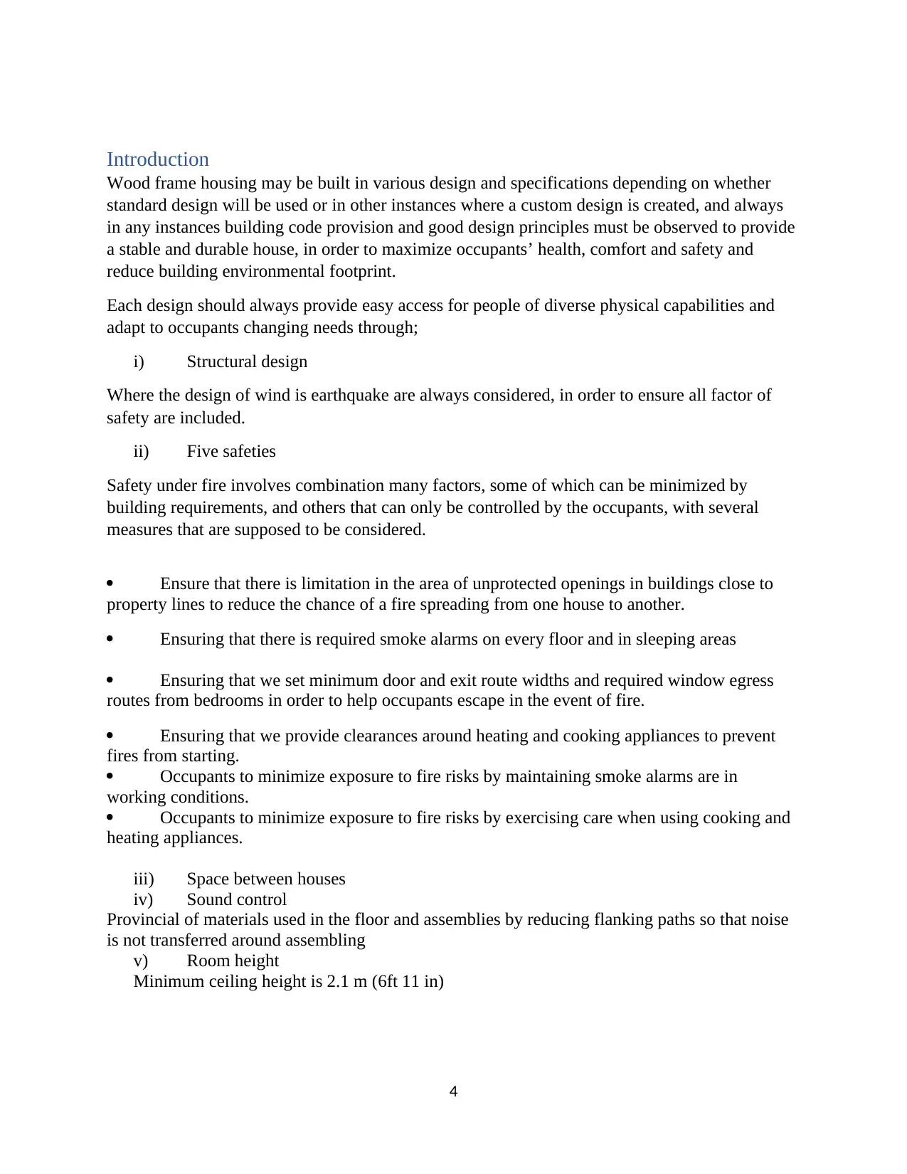
Introduction
Wood frame housing may be built in various design and specifications depending on whether
standard design will be used or in other instances where a custom design is created, and always
in any instances building code provision and good design principles must be observed to provide
a stable and durable house, in order to maximize occupants’ health, comfort and safety and
reduce building environmental footprint.
Each design should always provide easy access for people of diverse physical capabilities and
adapt to occupants changing needs through;
i) Structural design
Where the design of wind is earthquake are always considered, in order to ensure all factor of
safety are included.
ii) Five safeties
Safety under fire involves combination many factors, some of which can be minimized by
building requirements, and others that can only be controlled by the occupants, with several
measures that are supposed to be considered.
Ensure that there is limitation in the area of unprotected openings in buildings close to
property lines to reduce the chance of a fire spreading from one house to another.
Ensuring that there is required smoke alarms on every floor and in sleeping areas
Ensuring that we set minimum door and exit route widths and required window egress
routes from bedrooms in order to help occupants escape in the event of fire.
Ensuring that we provide clearances around heating and cooking appliances to prevent
fires from starting.
Occupants to minimize exposure to fire risks by maintaining smoke alarms are in
working conditions.
Occupants to minimize exposure to fire risks by exercising care when using cooking and
heating appliances.
iii) Space between houses
iv) Sound control
Provincial of materials used in the floor and assemblies by reducing flanking paths so that noise
is not transferred around assembling
v) Room height
Minimum ceiling height is 2.1 m (6ft 11 in)
4
Paraphrase This Document
Need a fresh take? Get an instant paraphrase of this document with our AI Paraphraser
5
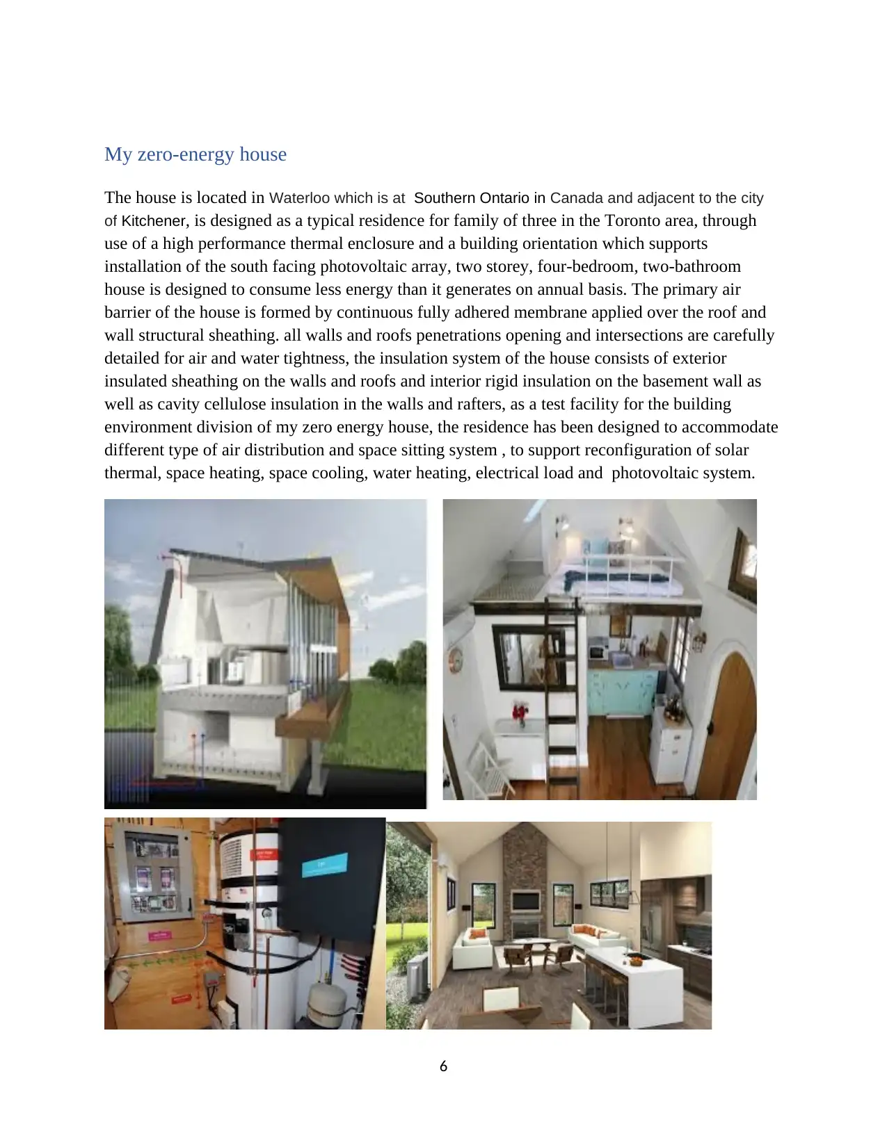
My zero-energy house
The house is located in Waterloo which is at Southern Ontario in Canada and adjacent to the city
of Kitchener, is designed as a typical residence for family of three in the Toronto area, through
use of a high performance thermal enclosure and a building orientation which supports
installation of the south facing photovoltaic array, two storey, four-bedroom, two-bathroom
house is designed to consume less energy than it generates on annual basis. The primary air
barrier of the house is formed by continuous fully adhered membrane applied over the roof and
wall structural sheathing. all walls and roofs penetrations opening and intersections are carefully
detailed for air and water tightness, the insulation system of the house consists of exterior
insulated sheathing on the walls and roofs and interior rigid insulation on the basement wall as
well as cavity cellulose insulation in the walls and rafters, as a test facility for the building
environment division of my zero energy house, the residence has been designed to accommodate
different type of air distribution and space sitting system , to support reconfiguration of solar
thermal, space heating, space cooling, water heating, electrical load and photovoltaic system.
6
⊘ This is a preview!⊘
Do you want full access?
Subscribe today to unlock all pages.
Trusted by 1+ million students worldwide
Component of the house
Framing
The Wood-frame construction comprises of the main structural members and sheathing, where a
combination of framing members and sheathing will provide rigidity, space for insulation and a
framework for supporting interior finishes and exterior components.
Floor Framing
The joist size for the lumber species and grade = 20 cm * 30 cm, joist spacing = 10 cm *
20 cm, span 500 cm and loads, the in-floor heating will require concrete topping, ensuring that
the floor joists should be deeper or more closely spaced.
The plumbing and ductwork will be installed without disrupting the floor system.
Wall Framing
usage of wood panel wall sheathing will provide a great significant resistance to lateral
loads from high winds and earthquakes, thicker sheathing, closer nailing patterns and the
provision of braced panels will be required to strengthen walls in order to sustain and curb risks
of high winds and earthquake loads.
A sheathing thickness of 20 cm and nailing patterns to provide adequate resistance to
lateral loads.
The walling arrangement will accommodate the necessary amount of insulation for your
climate zone.
The wall framing should be deep enough for the required insulation and locate pipes or
ducts in interior walls.
Roof Framing
The roof will be designed in order support local snow and wind loads and the weight of
the roofing materials that will be used.
it will also be considered in designing the roof structure in order to support future solar
thermal, photovoltaic panels, and it should address loading and electrical requirements.
The applied raised-heel trusses or deep rafters will be used in order to create room for
adequate ceiling insulation where the roof meets the wall.
There will be adequate ventilation in the roof space to prevent moisture from
accumulating in the attic.
Exterior Finishes
The cladding will be used as a first plane of protection for water penetration control. Exterior
finishes will include a wide variety of cladding materials as well as flashing, trim boards and
sealant, bearing in mind that windows and doors and the roof covering are also part of the
exterior finishes.
7
Paraphrase This Document
Need a fresh take? Get an instant paraphrase of this document with our AI Paraphraser
Flashing
Flashing will be installed in order to prevent water from entering the building envelope and to
intercept any water that passes the first plane of protection and direct it to the exterior.
It should always be noted that flashing is usually required wherever there is a discontinuity on
exterior surfaces where there is a change in cladding materials and at roof valleys.
Attics, Roof Spaces and Roofing
Unconditioned attics will be separated from the conditioned environment by insulation, an air
barrier system and a vapor barrier, it will be vented to remove any moisture that has entered from
the conditioned interior environment or the exterior environment.
The roof shape must effectively shed water and be covered with roofing materials and flashing
that will prevent water from entering.
Windows, Doors and Skylights
Windows, doors and skylights will separate the indoor and outdoor environments, provide
security and natural light, and must also provide a degree of thermal insulation.
Windows and Skylights
The choose windows and skylights should ensure enough light and fresh air in the house, and to
reduce winter heat loss and summer solar heat.
The windows near the ground must provide resistance to forced entry.
Carefully design will be done on windows in order to flash and drain to prevent water
from entering the interior space and the adjacent wall assemblies, and how it will be connected to
the air barrier system.
Doors
Exterior doors will meet most of the same performance requirements as windows for
heat, air and moisture control. Doors should be located under overhang protection, whenever
possible.
Choose doors will be insulated to reduce heat loss and that have durable seals and
weather-stripping.
Manufactured exterior doors, frames, locks, latches and hinges meet a standard for
resistance to forced entry. Any site-built exterior doors must also resist forced entry.
Stairs
The stairs will be wide enough and have sufficient headroom to provide safe passage.
8
Increasing energy efficiency in the house
Moisture, Air Leakage, Vapor Diffusion and Heat Transfer Control
Continuous insulation will be needed to provide energy efficiency and comfort. A continuous air
barrier system will restrict air movement into and out of a house, help provide thermal comfort,
reduce heat loss and avoid moisture condensation in the walls and ceilings that can cause
damage.
A vapor barrier prevents water vapor from migrating into the framing and insulation.
A sheathing membrane is installed over the exterior sheathing to prevent inward migration of
water that penetrates beyond the cladding. The membrane should also allow vapor that has
migrated from the conditioned space to dissipate to the exterior.
Water Penetration Control
Cladding forms a first plane of protection and is detailed to limit the amount of water that
gets past it.
The sheathing membrane is a second plane of protection that prevents water from
entering the building envelope and allows water vapor to drain and diffuse out of a wall
assembly.
Other materials used as sheathing membrane including asphalt-impregnated paper (tar
paper), spun-bonded polyolefin and self-adhering or liquid waterproof membranes.
A rain screen will be required in wet climates, to allow water that gets past the cladding
to drain to the exterior and to allow the space to dry.
Air Leakage Control
The air barrier system required will be continuous around the entire surface that separates
the conditioned environment from the unconditioned environment, therefore, the components
that make up this environmental separator must be sealed to each other to make the air barrier
system airtight. The air barrier system must be capable of resisting wind loads.
Air barrier system used will be 0.15 mm (6 mil) polyethylene installed on the interior of
the insulation with all joints and penetrations taped or sealed.
Plumbing, Electrical, Heating and Ventilation
Avoidance in the penetration of the air barrier system with plumbing, electrical or other
components.
i) Plumbing
This involve plan for all pipes, conduits and drains that must be installed in the basement
floor.
On radon control, an installation of an inverted ‘T’ shaped PVC pipe will be done in a
convenient location below the basement floor slab, with the vertical leg extending up through the
slab and capped.
9
⊘ This is a preview!⊘
Do you want full access?
Subscribe today to unlock all pages.
Trusted by 1+ million students worldwide
A fan and exhaust will be used to depressurize the gravel below the slab if radon gas is
detected.
ii) Electrical
The electrical meter location is installed at easily serviced area, with electric utility
provider and not detracted from the appearance of the house.
The conduit from the hydro service to the meter will be buried to avoid having overhead
wires. The electric service panel will also be installed
iii) Heating and Ventilation
The location of heating and ventilation ductwork will be done.
The low-noise source exhaust fans will also be installed and used.
Interior Wall and Ceiling Finishes
The use of gypsum board is to be used for interior finish of the house. The gypsum will provide a
smooth, paintable surface, it will also provide a degree of fire resistance to lightweight structural
framing, allowing walls and floors to remain in place to provide some time for occupants to
become aware of a fire and exit the building. Interior partitions also play a role in reducing sound
transmission. Gypsum board also provides a degree of lateral resistance to wall assemblies.
Painted gypsum board tightly fitted and sealed to other air barrier materials can also be part of
the air barrier system.
Floor Coverings
Since the floors are subject to wear and tear, the floor will be subjected to strong durable
materials
10
Paraphrase This Document
Need a fresh take? Get an instant paraphrase of this document with our AI Paraphraser
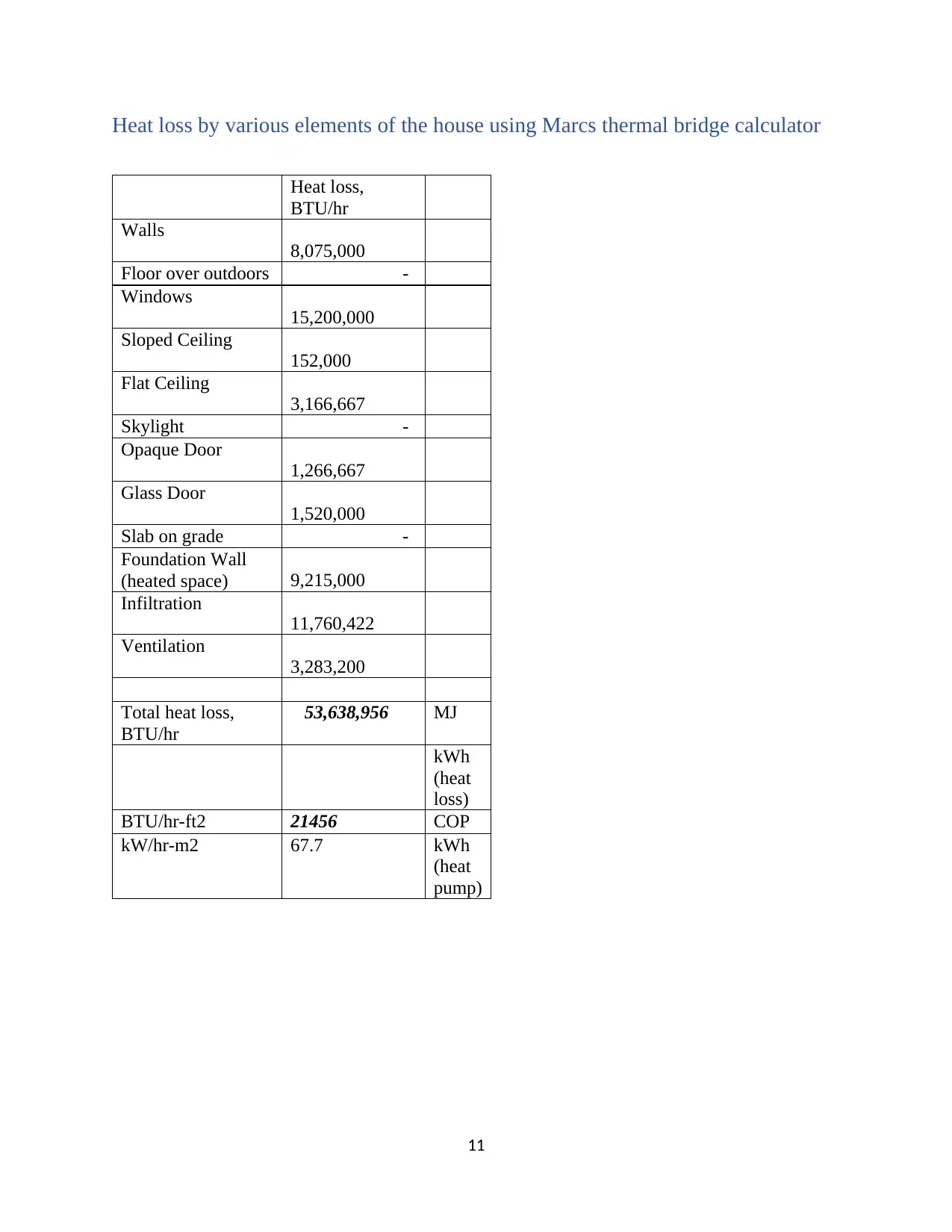
Heat loss by various elements of the house using Marcs thermal bridge calculator
Heat loss,
BTU/hr
Walls
8,075,000
Floor over outdoors -
Windows
15,200,000
Sloped Ceiling
152,000
Flat Ceiling
3,166,667
Skylight -
Opaque Door
1,266,667
Glass Door
1,520,000
Slab on grade -
Foundation Wall
(heated space) 9,215,000
Infiltration
11,760,422
Ventilation
3,283,200
Total heat loss,
BTU/hr
53,638,956 MJ
kWh
(heat
loss)
BTU/hr-ft2 21456 COP
kW/hr-m2 67.7 kWh
(heat
pump)
11
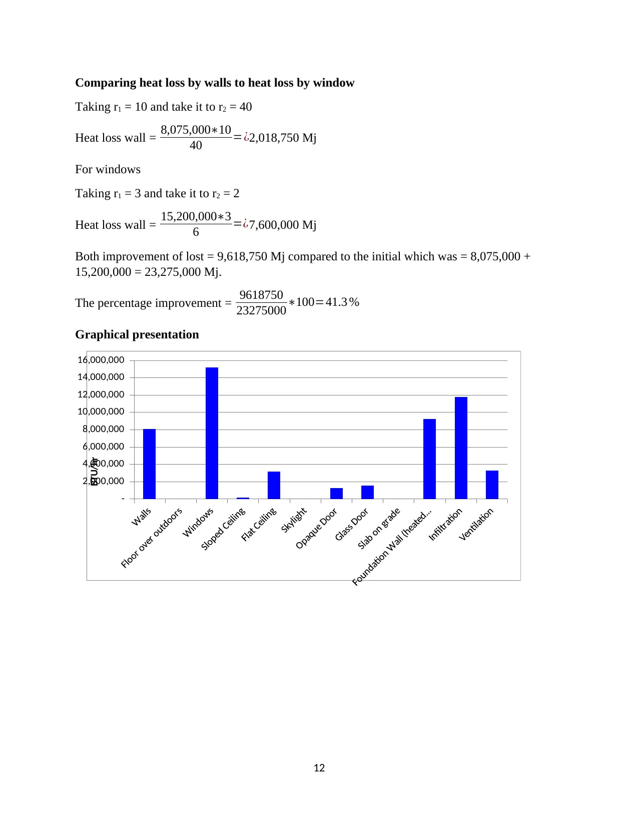
Comparing heat loss by walls to heat loss by window
Taking r1 = 10 and take it to r2 = 40
Heat loss wall = 8,075,000∗10
40 =¿2,018,750 Mj
For windows
Taking r1 = 3 and take it to r2 = 2
Heat loss wall = 15,200,000∗3
6 =¿7,600,000 Mj
Both improvement of lost = 9,618,750 Mj compared to the initial which was = 8,075,000 +
15,200,000 = 23,275,000 Mj.
The percentage improvement = 9618750
23275000∗100=41.3 %
Graphical presentation
-
2,000,000
4,000,000
6,000,000
8,000,000
10,000,000
12,000,000
14,000,000
16,000,000
BTU/hr
12
⊘ This is a preview!⊘
Do you want full access?
Subscribe today to unlock all pages.
Trusted by 1+ million students worldwide
1 out of 17
Related Documents


Your All-in-One AI-Powered Toolkit for Academic Success.
+13062052269
info@desklib.com
Available 24*7 on WhatsApp / Email
![[object Object]](/_next/static/media/star-bottom.7253800d.svg)
Unlock your academic potential
Copyright © 2020–2026 A2Z Services. All Rights Reserved. Developed and managed by ZUCOL.