ENGIN5302 Modelling & Simulation Project: Structural Assessment

Verified

Added on  2023/03/29

|7
|494
|209
Project
AI Summary
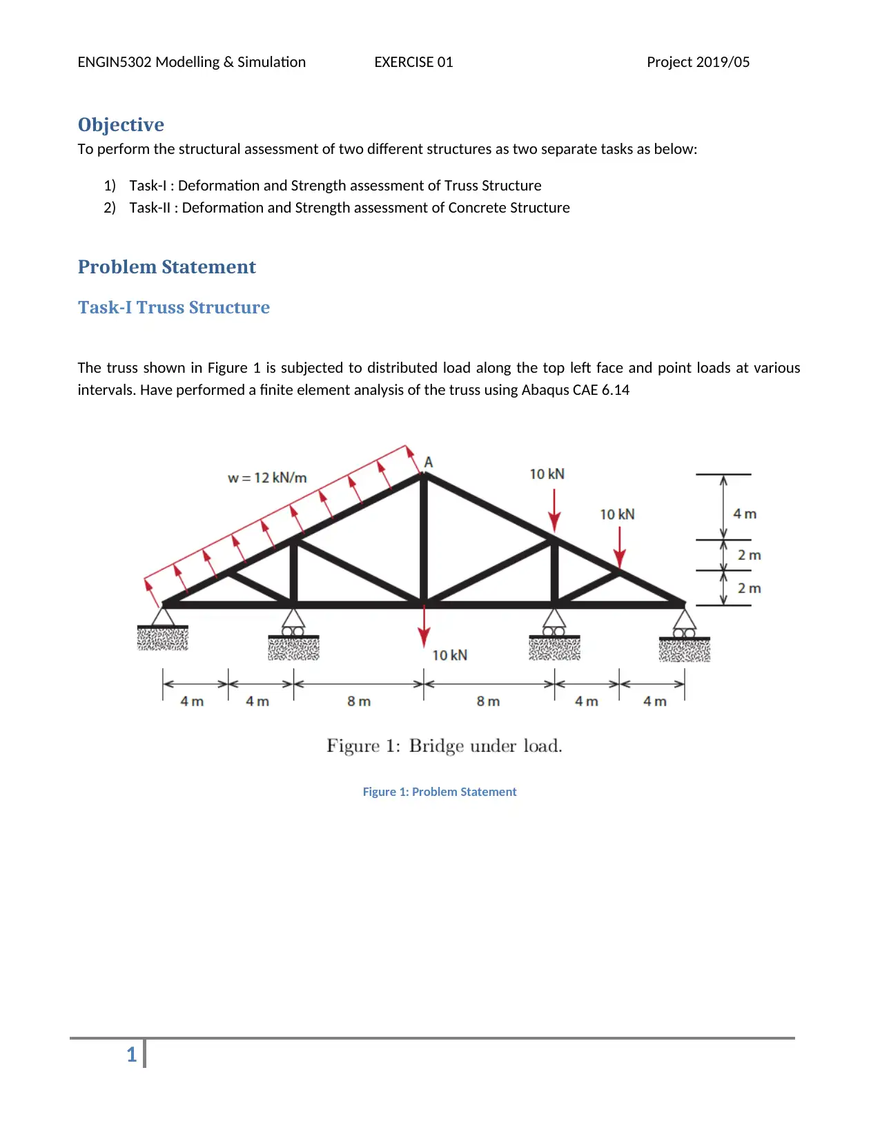
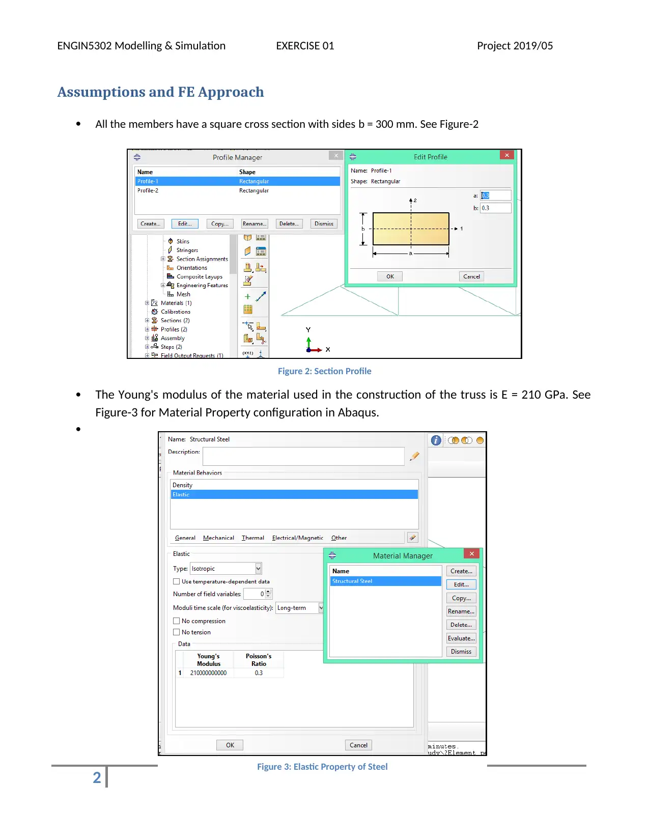
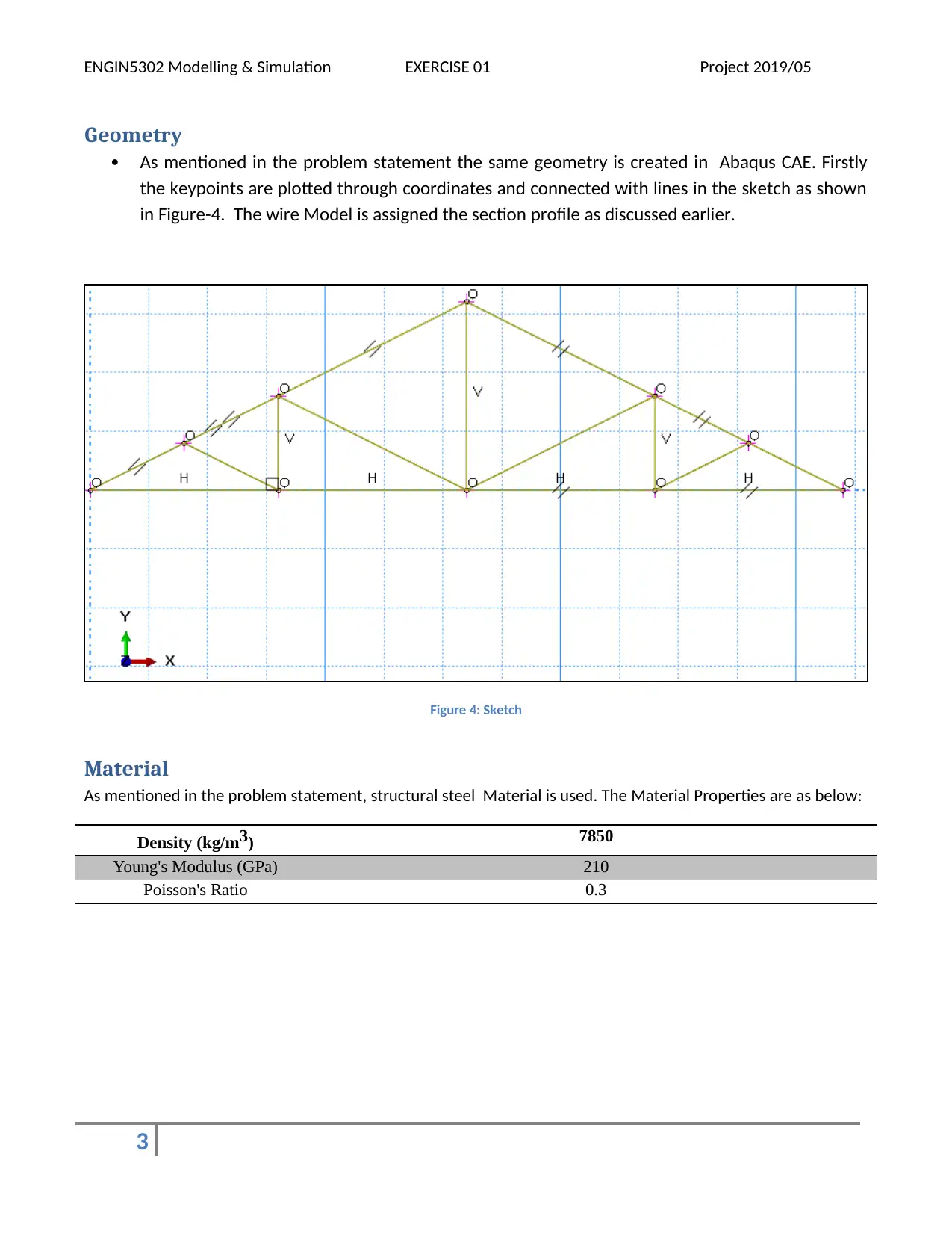
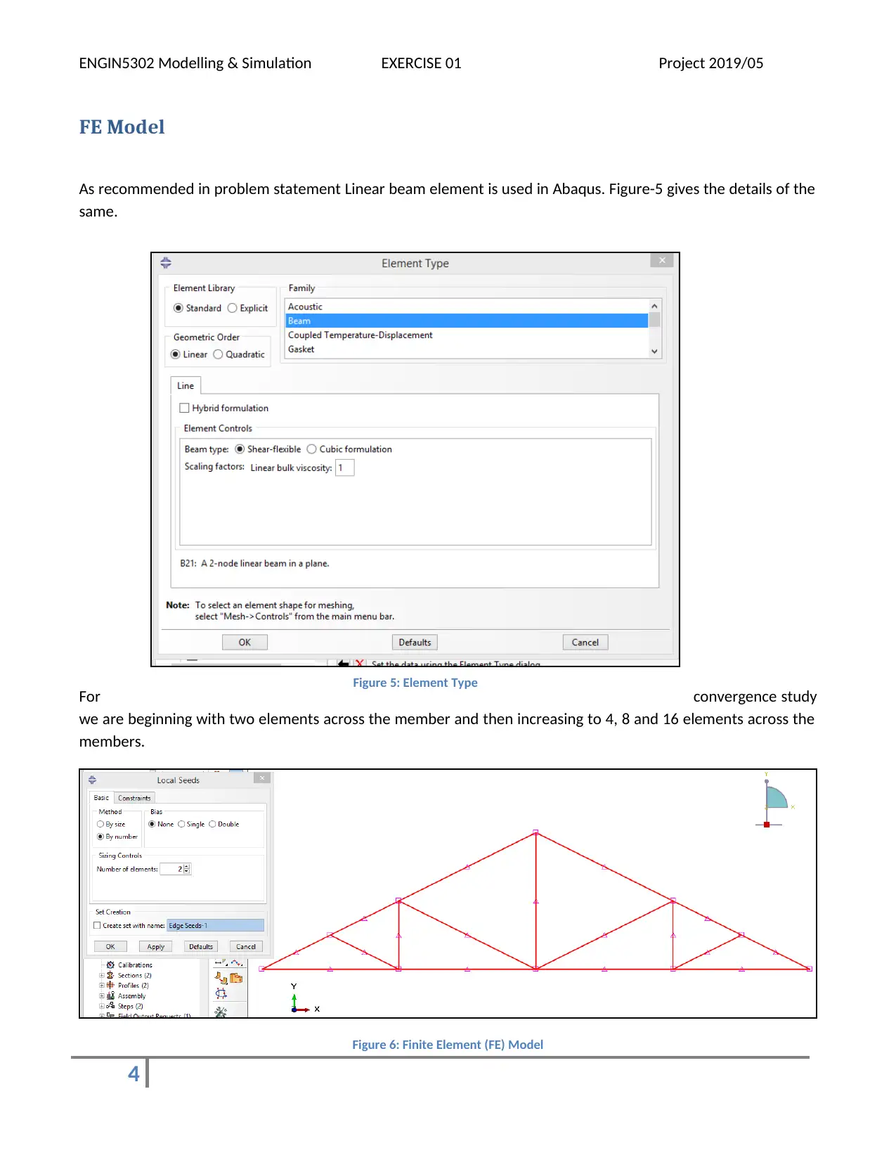
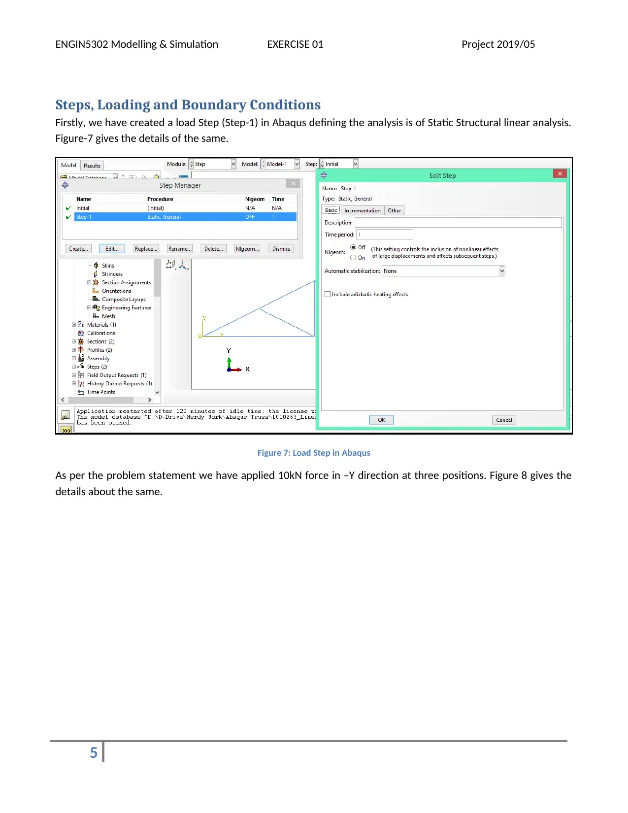
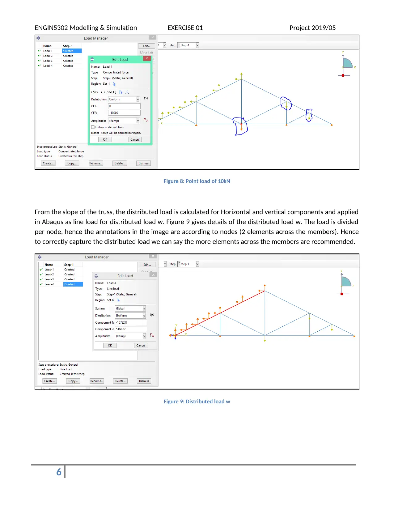
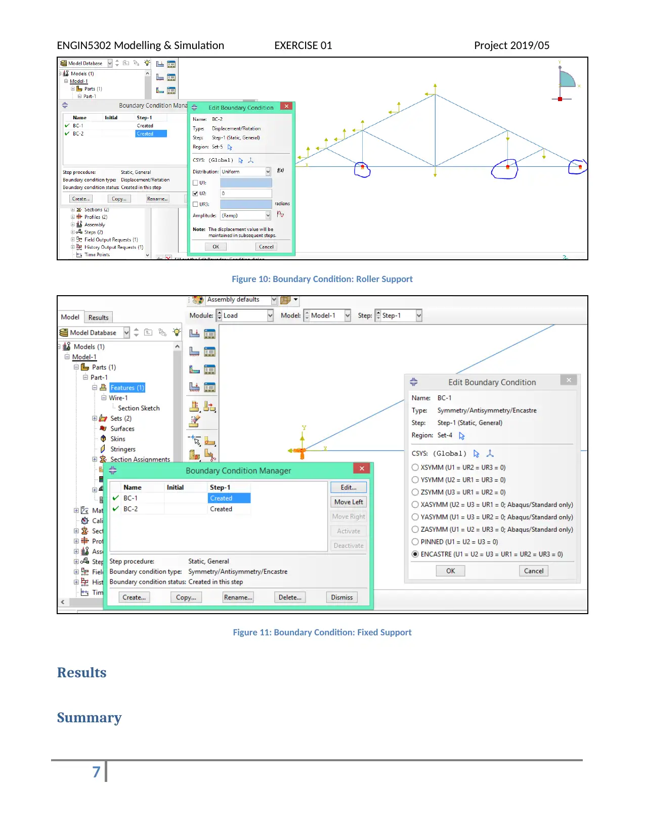
This document presents a solution to ENGIN5302 Modelling & Simulation Project focusing on the structural assessment of truss and concrete structures using finite element analysis (FEA) in Abaqus. Task-I involves analyzing a truss structure subjected to distributed and point loads, with considerations for material properties, geometry, and boundary conditions. The solution details the FE model setup, including element type, convergence study, and load application. Task-II, as mentioned in the assignment brief, involves the FEA analysis of a concrete overpass structure. The document includes the deformed shape of the truss, stress contour, and the location of maximum stress and deflection. This comprehensive solution is ideal for students seeking to understand and replicate structural analysis techniques using Abaqus, with Desklib providing additional resources for further study.
Document Page
ENGIN5302 Modelling & Simulation EXERCISE 01 Project 2019/05
Objective
To perform the structural assessment of two different structures as two separate tasks as below:
1) Task-I : Deformation and Strength assessment of Truss Structure
2) Task-II : Deformation and Strength assessment of Concrete Structure
Problem Statement
Task-I Truss Structure
The truss shown in Figure 1 is subjected to distributed load along the top left face and point loads at various
intervals. Have performed a finite element analysis of the truss using Abaqus CAE 6.14
Figure 1: Problem Statement
1
tabler-icon-diamond-filled.svg

Paraphrase This Document

Need a fresh take? Get an instant paraphrase of this document with our AI Paraphraser
Document Page
ENGIN5302 Modelling & Simulation EXERCISE 01 Project 2019/05
Assumptions and FE Approach
All the members have a square cross section with sides b = 300 mm. See Figure-2
The Young's modulus of the material used in the construction of the truss is E = 210 GPa. See
Figure-3 for Material Property configuration in Abaqus.

2
Figure 2: Section Profile
Figure 3: Elastic Property of Steel
Document Page
ENGIN5302 Modelling & Simulation EXERCISE 01 Project 2019/05
Geometry
As mentioned in the problem statement the same geometry is created in Abaqus CAE. Firstly
the keypoints are plotted through coordinates and connected with lines in the sketch as shown
in Figure-4. The wire Model is assigned the section profile as discussed earlier.
Figure 4: Sketch
Material
As mentioned in the problem statement, structural steel Material is used. The Material Properties are as below:
Density (kg/m3) 7850
Young's Modulus (GPa) 210
Poisson's Ratio 0.3
3
Document Page
ENGIN5302 Modelling & Simulation EXERCISE 01 Project 2019/05
FE Model
As recommended in problem statement Linear beam element is used in Abaqus. Figure-5 gives the details of the
same.
For convergence study
we are beginning with two elements across the member and then increasing to 4, 8 and 16 elements across the
members.
Figure 6: Finite Element (FE) Model
4
Figure 5: Element Type
tabler-icon-diamond-filled.svg

Paraphrase This Document

Need a fresh take? Get an instant paraphrase of this document with our AI Paraphraser
Document Page
ENGIN5302 Modelling & Simulation EXERCISE 01 Project 2019/05
Steps, Loading and Boundary Conditions
Firstly, we have created a load Step (Step-1) in Abaqus defining the analysis is of Static Structural linear analysis.
Figure-7 gives the details of the same.
Figure 7: Load Step in Abaqus
As per the problem statement we have applied 10kN force in –Y direction at three positions. Figure 8 gives the
details about the same.
5
Document Page
ENGIN5302 Modelling & Simulation EXERCISE 01 Project 2019/05
Figure 8: Point load of 10kN
From the slope of the truss, the distributed load is calculated for Horizontal and vertical components and applied
in Abaqus as line load for distributed load w. Figure 9 gives details of the distributed load w. The load is divided
per node, hence the annotations in the image are according to nodes (2 elements across the members). Hence
to correctly capture the distributed load we can say the more elements across the members are recommended.
Figure 9: Distributed load w
6
Document Page
ENGIN5302 Modelling & Simulation EXERCISE 01 Project 2019/05
Figure 10: Boundary Condition: Roller Support
Figure 11: Boundary Condition: Fixed Support
Results
Summary
7
chevron_up_icon
1 out of 7
circle_padding
hide_on_mobile
zoom_out_icon
[object Object]