Electrical Engineering Project: DC Motor Speed Control and Analysis

Verified

Added on  2020/03/04

|10
|1743
|162
Report
AI Summary
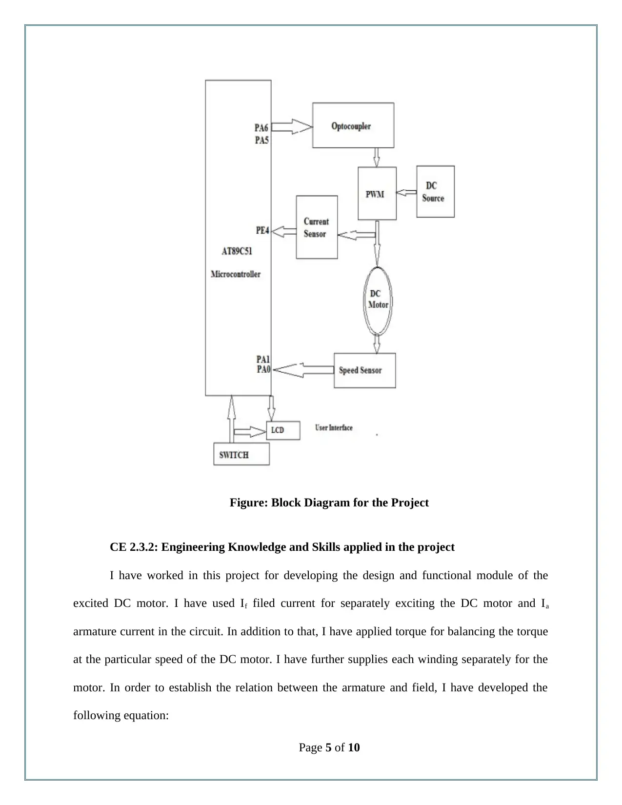
This report details a student's project focused on controlling the speed of a DC motor. The project involved using an AT89C51 microcontroller and PWM techniques to regulate motor speed. The report covers the project's background, objectives, and the student's role as a team member, including responsibilities in identifying technical requirements, implementing PWM, and gathering data. Key aspects include the application of engineering knowledge, such as equations for instantaneous field and armature current, and practical implementation using hardware components like optocouplers, DC sources, and speed sensors. The student faced challenges in connecting hardware elements, which were resolved by verifying voltage tolerances. The project culminated in a successful prototype, demonstrating the ability to control motor speed and direction. The report also highlights collaborative work and the project's overview, summarizing the achievements and the student's contributions to the design and implementation of the DC motor speed controller.
Document Page
Competency Demonstration Report (CDR)
Career Episode 2
tabler-icon-diamond-filled.svg

Paraphrase This Document

Need a fresh take? Get an instant paraphrase of this document with our AI Paraphraser
Document Page
CE 2.1: Project Introduction
Name of the Project : Controlling Speed of DC motor
Geographical Location :[Please Fill]
Project Duration : [Please Fill]
Organization : [Please Fill]
Position in the Project : Team Member
CE 2.2: Project Background
CE 2.2.1: Characteristics of the Project
The drive system used for the industrial application and machineries has significantly
increased in order to achieve the high reliability and performance capabilities. DC motor is
extensively used in various appliances and equipments for providing load characteristics and
variable speed of the motor. The ability to control and modify the speed of the machines for
improving the performance while providing fast response time and precise control over the
operation. Increasing the speed of the DC motor helps in enhancing the performance and
productivity of the system. Therefore, in this project I have aimed at controlling the speed of a
DC motor. In this project, I have used microcontroller for controlling and monitoring the speed
of the DC motor. In addition to that, I have implemented the DC motor speed control system
with AT89C51 Microcontrollers and fed the control obtained from the microcontroller in a DC
chopper.
Page 1 of 10
Document Page
CE 2.2.2: Objectives developed for project
While working on this project, I have aimed at developing an application on controlling
the speed of the DC motor and apply it in the domestic appliances. I have used PIC
microcontroller for controlling the actual speed of the motor. The application of the DC motor
speed controller would help controlling the automation of the machineries in various industries.
The development of the DC motor speed controller helps in initially detecting the current speed
of the motor and control the speed based on the input provided by the user. Therefore, for
completing the design and implementation of the DC speed controller, I have developed the
following objectives:
ï‚· To identify the block diagram for the DC motor speed controller;
ï‚· To identify the various hardware element required and determine the connectivity
between them;
ï‚· To develop the model for DC motor and PWM technique;
ï‚· To develop the prototype model of the DC motor speed controller;
ï‚· To evaluate and determine the performance of the developed prototype model;
CE 2.2.3: My area of work
I have identified term functional module and operational requirements for controlling the
speed of the DC motor. I have used PIC AT89C51 microcontroller that has allowed me to reduce
the overall cost for implementation. I have figured out the technical requirements and
specification for implementing the DC motor controller.
CE 2.2.4: Project Group
Page 2 of 10
Document Page
Figure 1: Team Member Associated for the development of the project
CE 2.2.5: My responsibilities throughout the project
As a team member I took multidimensional responsibility throughout the entire project. I
took entire responsibility of figuring out the technical requirement and process to employee
PMW techniques for controlling after DC motor. I have gathered the information and data
obtained during the implementation and testing phase of the project for preparing the project
report. I have worked alongside two team members for developing the hardware module and
conducting the efficiency test of the speed controller.
CE 2.3: Distinctive Activity
Page 3 of 10
tabler-icon-diamond-filled.svg

Paraphrase This Document

Need a fresh take? Get an instant paraphrase of this document with our AI Paraphraser
Document Page
CE 2.3.1: Comprehending the Theory of the project
I have used AT89C51 Microcontrollers for controlling the speed of the DC motor. In
addition to that, I have used DC chopper for feeding the data. PWM signal technique has been
utilized for driving the functionality of the DC chopper. After providing appropriate power
supply the PIC microcontroller, I have used the PIC for detecting the current speed of the DC
motor. 5 V Dc pulse is generated by the microcontroller in the form of PWM signal that is being
fed to the driver circuit. The 12 v DC pulse obtained from the driver circuit has been utilized for
triggering the MOSFET. In addition to that, I have used the PWM duty cycle for controlling the
speed of the DC motor.
Page 4 of 10
Document Page
Figure: Block Diagram for the Project
CE 2.3.2: Engineering Knowledge and Skills applied in the project
I have worked in this project for developing the design and functional module of the
excited DC motor. I have used If filed current for separately exciting the DC motor and Ia
armature current in the circuit. In addition to that, I have applied torque for balancing the torque
at the particular speed of the DC motor. I have further supplies each winding separately for the
motor. In order to establish the relation between the armature and field, I have developed the
following equation:
Page 5 of 10
Document Page
Instantaneous field current = Vr = Rf if + Lf d if /dt
In the above equation, I have used Lf and Rf for representing field inductor and field
resistor respectively. On the other hand, for determining the Instantaneous armature current, I
have utilized the following equation:
Instantaneous armature current = Va = Ra ia + La dia / dt - rg
In the above equation, I have used La and Ra for determining the armature inductor and
armature resistor respectively.
Furthermore, in this project, I have conducted tolerance analysis for dealing with the
overloading damages on the DC motor. I have used a buck converter and connected a
thermometer on the transistors. In addition to that, I have started the load of 150 W and run the
system for continuous 5 minutes for recording the temperature. Accordingly I have gradually
increased the power input and calculated the lost power after each rise of power input by 10 W. I
have tested the motor with 500 W cases and used power resistors for meeting the proposed
requirement.
CE 2.3.3: Accomplishment and Task Performed
For the development of the prototype model of the Dc motor speed controller, I have used
AT89C51 microcontroller, Optocoupler , Dc source, Speed sensor, current sensor, PWM circuit
and DC motor. In addition to that, I was successful in developing the circuitry and hardware
implementation of the speed controller. All the hardware and software components of the speed
controller were efficiently connected based on the identified parameter.
CE 2.3.4: Identified Issues and Their Solutions
Page 6 of 10
tabler-icon-diamond-filled.svg

Paraphrase This Document

Need a fresh take? Get an instant paraphrase of this document with our AI Paraphraser
Document Page
Issue: I have selected the hardware element that has been implemented in the project for
the development of the prototype model of the DC motor speed controller. I have faced
significant issue while implementing the connection between the hardware elements used in the
system. During the initial development of prototype model the microcontroller got burnt due to
supply of high voltage.
Solution: In order to mitigate the issue, I have checked and evaluated and verifies the
optimum voltage tolerance for all the hardware units used in the project. I have observed that I
have used the dc shunt motor with the capacity of 220 v and 2.2 A. whereas the capacity of the
microcontroller is 5V. Therefore I have connected the optical coupler and PWM with external
power sources. Therefore, I have ensured 5v is supplied to the microcontroller, 220 v to the
PWM unit and 20V to the optical coupler unit.
CE 2.3.5: Plan for producing creative and innovative work
I have used Full H Bridge Motor Drive and PWM for controlling the speed of the DC
motor. For this I have implemented a simple circuit in which I have connected the battery as the
source of power through Metal-Oxide Semiconductor Field Effect Transistor (MOSFET). I have
ensured 12 v of current in the motor when the close switch is observed and 0 v when the circuit
is kept open. I have used MOSFET for controlling the opening and closing of the circuit. For
determining the voltage supplied to the DC motor, I have used the following formula:
V avg = (ton / T) * V in
In the above equation, I have used Vavg for indicating the average supply of voltage, T as
the PWM period, ton as the time consumed by the On switch and for representing the DC duty
cycle, I have used (ton / T). Through the determination of the PWM signal, I have ensured that the
Page 7 of 10
Document Page
speed of the DC motor increased based on the amount of time, the voltage is kept on for the
system. On the other hand, the inertia of the motor plays a significant role in slowing down the
speed of the DC motor.
CE 2.3.6: Collaborative work
I have followed collaborative work and encouraged continuous team work during the
development of speed controller. I have arranged weekly meeting with the assistant professor
and team leader for discussing about project progress and technologies that are being used
throughout the project. The team work and continuous collaboration with the team members has
allowed me to efficiently carry out the implementation of DC motor controller.
CE 2.4: Project Review
CE 2.4.1: Project Overview
The final prototype model developed for controlling the speed of the DC motor was a
success. The Dc motor was rotating at steady speed in one direction, and the direction of the
motor can be efficiently and effectively reserved as required. In addition to that, the speed of the
DC motor was decreased and increased as desired through external output with time. The
variation of the PWM signal has allowed me in easily controlling the motor driver and changes
the speed of the motor.
CE 2.4.2: My contribution to work
Page 8 of 10
Document Page
Being associated in this project as a team member I have contributed with my theoretical
knowledge and Technical skills for the design and implementation of DC motor speed controller.
I was successful in developing the separate excited DC motor along with the application of
PWM techniques for controlling the speed of the motor from external output.
Page 9 of 10
chevron_up_icon
1 out of 10
circle_padding
hide_on_mobile
zoom_out_icon
[object Object]